EP4579098A1 - Torsionsdämpfer und kupplungsscheibe - Google Patents
Torsionsdämpfer und kupplungsscheibe Download PDFInfo
- Publication number
- EP4579098A1 EP4579098A1 EP24220818.9A EP24220818A EP4579098A1 EP 4579098 A1 EP4579098 A1 EP 4579098A1 EP 24220818 A EP24220818 A EP 24220818A EP 4579098 A1 EP4579098 A1 EP 4579098A1
- Authority
- EP
- European Patent Office
- Prior art keywords
- friction
- washer
- rotation
- axis
- torsion damper
- Prior art date
- Legal status (The legal status is an assumption and is not a legal conclusion. Google has not performed a legal analysis and makes no representation as to the accuracy of the status listed.)
- Pending
Links
Images

Classifications
-
- F—MECHANICAL ENGINEERING; LIGHTING; HEATING; WEAPONS; BLASTING
- F16—ENGINEERING ELEMENTS AND UNITS; GENERAL MEASURES FOR PRODUCING AND MAINTAINING EFFECTIVE FUNCTIONING OF MACHINES OR INSTALLATIONS; THERMAL INSULATION IN GENERAL
- F16F—SPRINGS; SHOCK-ABSORBERS; MEANS FOR DAMPING VIBRATION
- F16F15/00—Suppression of vibrations in systems; Means or arrangements for avoiding or reducing out-of-balance forces, e.g. due to motion
- F16F15/10—Suppression of vibrations in rotating systems by making use of members moving with the system
- F16F15/12—Suppression of vibrations in rotating systems by making use of members moving with the system using elastic members or friction-damping members, e.g. between a rotating shaft and a gyratory mass mounted thereon
- F16F15/129—Suppression of vibrations in rotating systems by making use of members moving with the system using elastic members or friction-damping members, e.g. between a rotating shaft and a gyratory mass mounted thereon characterised by friction-damping means
-
- F—MECHANICAL ENGINEERING; LIGHTING; HEATING; WEAPONS; BLASTING
- F16—ENGINEERING ELEMENTS AND UNITS; GENERAL MEASURES FOR PRODUCING AND MAINTAINING EFFECTIVE FUNCTIONING OF MACHINES OR INSTALLATIONS; THERMAL INSULATION IN GENERAL
- F16F—SPRINGS; SHOCK-ABSORBERS; MEANS FOR DAMPING VIBRATION
- F16F15/00—Suppression of vibrations in systems; Means or arrangements for avoiding or reducing out-of-balance forces, e.g. due to motion
- F16F15/10—Suppression of vibrations in rotating systems by making use of members moving with the system
- F16F15/12—Suppression of vibrations in rotating systems by making use of members moving with the system using elastic members or friction-damping members, e.g. between a rotating shaft and a gyratory mass mounted thereon
- F16F15/121—Suppression of vibrations in rotating systems by making use of members moving with the system using elastic members or friction-damping members, e.g. between a rotating shaft and a gyratory mass mounted thereon using springs as elastic members, e.g. metallic springs
- F16F15/123—Wound springs
- F16F15/1232—Wound springs characterised by the spring mounting
-
- F—MECHANICAL ENGINEERING; LIGHTING; HEATING; WEAPONS; BLASTING
- F16—ENGINEERING ELEMENTS AND UNITS; GENERAL MEASURES FOR PRODUCING AND MAINTAINING EFFECTIVE FUNCTIONING OF MACHINES OR INSTALLATIONS; THERMAL INSULATION IN GENERAL
- F16D—COUPLINGS FOR TRANSMITTING ROTATION; CLUTCHES; BRAKES
- F16D13/00—Friction clutches
- F16D13/58—Details
-
- F—MECHANICAL ENGINEERING; LIGHTING; HEATING; WEAPONS; BLASTING
- F16—ENGINEERING ELEMENTS AND UNITS; GENERAL MEASURES FOR PRODUCING AND MAINTAINING EFFECTIVE FUNCTIONING OF MACHINES OR INSTALLATIONS; THERMAL INSULATION IN GENERAL
- F16D—COUPLINGS FOR TRANSMITTING ROTATION; CLUTCHES; BRAKES
- F16D13/00—Friction clutches
- F16D13/58—Details
- F16D13/60—Clutching elements
- F16D13/64—Clutch-plates; Clutch-lamellae
-
- F—MECHANICAL ENGINEERING; LIGHTING; HEATING; WEAPONS; BLASTING
- F16—ENGINEERING ELEMENTS AND UNITS; GENERAL MEASURES FOR PRODUCING AND MAINTAINING EFFECTIVE FUNCTIONING OF MACHINES OR INSTALLATIONS; THERMAL INSULATION IN GENERAL
- F16D—COUPLINGS FOR TRANSMITTING ROTATION; CLUTCHES; BRAKES
- F16D13/00—Friction clutches
- F16D13/58—Details
- F16D13/70—Pressure members, e.g. pressure plates, for clutch-plates or lamellae; Guiding arrangements for pressure members
-
- F—MECHANICAL ENGINEERING; LIGHTING; HEATING; WEAPONS; BLASTING
- F16—ENGINEERING ELEMENTS AND UNITS; GENERAL MEASURES FOR PRODUCING AND MAINTAINING EFFECTIVE FUNCTIONING OF MACHINES OR INSTALLATIONS; THERMAL INSULATION IN GENERAL
- F16D—COUPLINGS FOR TRANSMITTING ROTATION; CLUTCHES; BRAKES
- F16D3/00—Yielding couplings, i.e. with means permitting movement between the connected parts during the drive
- F16D3/02—Yielding couplings, i.e. with means permitting movement between the connected parts during the drive adapted to specific functions
- F16D3/12—Yielding couplings, i.e. with means permitting movement between the connected parts during the drive adapted to specific functions specially adapted for accumulation of energy to absorb shocks or vibration
-
- F—MECHANICAL ENGINEERING; LIGHTING; HEATING; WEAPONS; BLASTING
- F16—ENGINEERING ELEMENTS AND UNITS; GENERAL MEASURES FOR PRODUCING AND MAINTAINING EFFECTIVE FUNCTIONING OF MACHINES OR INSTALLATIONS; THERMAL INSULATION IN GENERAL
- F16D—COUPLINGS FOR TRANSMITTING ROTATION; CLUTCHES; BRAKES
- F16D13/00—Friction clutches
- F16D13/58—Details
- F16D13/60—Clutching elements
- F16D13/64—Clutch-plates; Clutch-lamellae
- F16D13/644—Hub construction
-
- F—MECHANICAL ENGINEERING; LIGHTING; HEATING; WEAPONS; BLASTING
- F16—ENGINEERING ELEMENTS AND UNITS; GENERAL MEASURES FOR PRODUCING AND MAINTAINING EFFECTIVE FUNCTIONING OF MACHINES OR INSTALLATIONS; THERMAL INSULATION IN GENERAL
- F16D—COUPLINGS FOR TRANSMITTING ROTATION; CLUTCHES; BRAKES
- F16D13/00—Friction clutches
- F16D13/58—Details
- F16D13/60—Clutching elements
- F16D13/64—Clutch-plates; Clutch-lamellae
- F16D13/68—Attachments of plates or lamellae to their supports
- F16D13/686—Attachments of plates or lamellae to their supports with one or more intermediate members made of rubber or like material transmitting torque from the linings to the hub
-
- F—MECHANICAL ENGINEERING; LIGHTING; HEATING; WEAPONS; BLASTING
- F16—ENGINEERING ELEMENTS AND UNITS; GENERAL MEASURES FOR PRODUCING AND MAINTAINING EFFECTIVE FUNCTIONING OF MACHINES OR INSTALLATIONS; THERMAL INSULATION IN GENERAL
- F16D—COUPLINGS FOR TRANSMITTING ROTATION; CLUTCHES; BRAKES
- F16D13/00—Friction clutches
- F16D13/58—Details
- F16D13/75—Features relating to adjustment, e.g. slack adjusters
-
- F—MECHANICAL ENGINEERING; LIGHTING; HEATING; WEAPONS; BLASTING
- F16—ENGINEERING ELEMENTS AND UNITS; GENERAL MEASURES FOR PRODUCING AND MAINTAINING EFFECTIVE FUNCTIONING OF MACHINES OR INSTALLATIONS; THERMAL INSULATION IN GENERAL
- F16D—COUPLINGS FOR TRANSMITTING ROTATION; CLUTCHES; BRAKES
- F16D2300/00—Special features for couplings or clutches
- F16D2300/22—Vibration damping
Definitions
- the aforementioned coupling elements (teeth, splines, lugs) must cooperate with minimal angular clearance. In the absence of angular clearance, axial movement of the friction washer would be difficult or even impossible due to axial friction between the teeth/splines...
- angular clearance means that the friction washer and the first element are not strictly integral in rotation with each other, especially since mauling phenomena between these coupling elements tend to amplify the initial angular clearance as the friction device operates.
- the vibrations passing through the damper generate shocks between the aforementioned coupling elements and the support component.
- the level of shock is such that it is possible to maul or shear these coupling elements.
- the shock absorber according to the invention aims to resolve the technical problems posed by the prior art by definitively eliminating the problems of matting while proposing a solution at a reduced cost.
- the shock absorber may include one or more of the following features:
- the first friction washer and the second friction washer are identical and positioned symmetrically with respect to the first element.
- the shock absorber is simple and inexpensive to produce due to the standardization of the parts.
- the first spring washer and the second spring washer are identical and positioned symmetrically with respect to the first element.
- the shock absorber is simple and inexpensive to produce due to the standardization of the parts.
- the second friction device further comprises a second shim washer arranged axially between the first element and the second elastic washer, the first shim washer and the second shim washer being identical and positioned symmetrically with respect to the first element.
- the second elastic washer is positioned optimally and maintains its position over time.
- the shock absorber is simple and inexpensive to produce due to the standardization of the parts.
- the first friction washer comprises only two fixing portions, each fixing portion being connected to the friction portion by a flexible element.
- the presence of only two fixing portions allows the first friction washer to have almost zero stiffness.
- the first friction washer is simple and inexpensive to produce.
- Each fixing portion is connected to the friction portion by a single flexible element.
- the first friction washer is simple and inexpensive to produce.
- the second friction washer comprises only two fixing portions, each fixing portion being connected to the friction portion by a flexible element.
- the presence of only two fixing portions allows the second friction washer to have almost zero stiffness.
- the second friction washer is simple and inexpensive to produce.
- Each fixing portion is connected to the friction portion by a single flexible element.
- the second friction washer is simple and inexpensive to produce.
- the flexible element is a flexible leg.
- the two fixing portions are arranged at 180 degrees to each other.
- the first and/or second friction washer is simple and inexpensive to produce.
- the two fixing portions are arranged between 50 and 110 degrees to each other.
- the two fixing portions are preferably arranged at 90 degrees from each other.
- the first and/or second friction washer can adapt to various ergonomic constraints of the shock absorber while maintaining almost zero stiffness.
- the first friction washer comprises at least three fixing portions, each fixing portion being connected to the friction portion by a flexible element comprising at least one corrugated part having, radially, a succession of zones axially offset two by two.
- a flexible element comprising at least one corrugated part having, radially, a succession of zones axially offset two by two.
- the second friction washer comprises at least three fixing portions, each fixing portion being connected to the friction portion by a flexible element comprising at least one corrugated part having, radially, a succession of zones axially offset two by two.
- the second friction washer is more robust while having almost zero stiffness.
- Each fixing portion is connected to the friction portion by a single flexible element.
- the first and/or second friction washer is simple and inexpensive to produce.
- the first element comprises an annular member such as a disc or a washer whose center is arranged on the X axis of rotation.
- Each attachment portion of the friction washer is attached to the first member or the second member via a support member.
- the torsion damper is capable of transmitting the torque from the vehicle's engine to the vehicle's drive wheels.
- the first element is intended to be driven in rotation by the engine of the vehicle
- the second element is intended to drive in rotation a gearbox input member of the vehicle, such as a shaft.
- the second element is intended to be driven in rotation by the engine of the vehicle
- the first element is intended to drive in rotation a gearbox input member of the vehicle, such as a shaft.
- the first elastic washer is arranged axially between the first element and the friction portion of the first friction washer, for axially pressing the friction portion of the first friction washer against a friction surface of the second element.
- Each fixing portion is axially locked on the first or second element.
- Each fixing portion is mounted so as to rotate securely with the first or second element, without angular play.
- the mounting of the fixing portions is not removable so as to avoid angular mounting clearances.
- the fixing portions are fixed in a non-removable manner to the first or second element.
- the fixing portion is connected to the first or second element by an embedment connection such as riveting or welding.
- An embedment connection is a connection with no degree of freedom.
- Each first or second element and each fixing portion each comprises at least one orifice, each fixing portion orifice being arranged opposite an orifice of the first or second element, and each fixing portion is rigidly fixed in rotation to the corresponding first or second element by means of at least one fixing element, such as a rivet or a pin.
- Each fixing portion is also axially locked on the first or second element by means of the fixing element.
- the fixing element may be a rivet comprising a barrel intended to be engaged in the orifices of the fixing portion and of the first or second element, and further comprising at each end a head enlarged relative to the barrel.
- the fixing portions are arranged radially outside the springs.
- the springs are helical springs that extend circumferentially or tangentially about the X-axis over a mean implantation radius, and the fixing portions are arranged radially outside the mean implantation radius.
- the average implantation radius is taken at the level of the middle zone of the length of a spring, and at the level of the main axis around which the coils are wound.
- Each flexible element is elastically deformable axially.
- the load exerted by the first elastic washer is greater than the load exerted by the flexible element(s) of the first friction washer.
- Each flexible element has a linear axial stiffness.
- Each flexible element is arranged circumferentially between two springs.
- the first element comprises openings for housing the springs and a support element arranged circumferentially between two neighboring openings. Each flexible element being rigidly secured to a support element of the first element.
- the friction portion is composed of a plurality of friction plates spaced apart from each other.
- the friction portion is composed of a single circular friction pad.
- Each fixing portion is arranged to receive one or two rivets.
- Each fixing portion is arranged circumferentially between two neighboring springs.
- the first friction washer is cut from a sheet metal.
- the first friction washer is flat before its mounting in the torsion damper.
- the deformation of the first friction washer during its assembly makes it possible to generate the axial load of the flexible elements, in particular in a direction opposite to the direction of the forces exerted by the first elastic washer.
- the second element comprises a first and a second lateral washer mounted integrally in rotation around the X axis and spaced apart axially from each other; and the first element comprises an intermediate disc arranged axially between the two side washers.
- the invention also relates to a clutch disc for a vehicle powertrain equipped with a damper as described above and a friction disc carried by the first element and provided with friction linings.
- a hub is rotationally fixed to the first and second side washers.
- the second element includes this hub.
- the hub is provided with a collar on either side of which the first and second side washers come into axial abutment.
- the hub and the first and second side washers are riveted together.
- the hub is an output hub capable of driving a gearbox input shaft.
- the hub is an intermediate hub coupled with angular clearance with an output hub
- the clutch disc further comprises a pre-damper provided with pre-damping springs kinematically arranged between the output hub and the second element.
- the clutch disc has an output hub driven in rotation directly or indirectly (via a pre-damper for example) by the first element.
- the friction disc and the first friction washer are fixed to the first element with the same fasteners, for example the same rivets.
- the friction disc, the first element (in particular the central disc), the first friction device and the second friction device together form a pre-assembled sub-assembly capable of being inserted between the first and second side washers.
- This subassembly is mounted without axial locking on the hub.
- the terms “external” and “internal” as well as the orientations “axial” and “radial” are used to designate, according to the definitions given in the description, elements of the shock absorber.
- the "radial” orientation is directed orthogonally to the axis of rotation X of the shock absorber determining the “axial” orientation and, from the inside to the outside away from said axis of rotation, the "circumferential” orientation is circular around the X axis and the tangential orientation is directed orthogonally to the axis of rotation of the shock absorber and orthogonally to the radial direction.
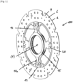
- FIG. 1 represents a perspective view of a clutch disc for a vehicle powertrain.
- the clutch disc is equipped with a damper 100 and a friction disc 6 provided with friction linings 7.
- the torsion damper 100 comprises a first element 1 capable of rotating around an axis X of rotation, and a second element movable in rotation relative to the first element 1 along the axis X. This torsion damper 100 is capable of transmitting torque from the vehicle's engine to the vehicle's drive wheels.
- Springs may be mounted between the first element 1 and the second element, so as to compress to allow relative rotation along the X axis between the first element 1 and the second element.
- the second element may comprise a first side washer and a second side washer mounted integrally in rotation around the axis X and spaced axially from each other.
- the first element 1 may comprise an intermediate disc 1a arranged axially between the two side washers.
- the friction disc 6 can be carried by the intermediate disc 1a at its outer periphery.
- the clutch disc may further comprise an output hub 40 driven in rotation indirectly, via a pre-damper, by the second element, via the first lateral washer.
- the output hub 40 may be coupled with an angular clearance with the second element.
- the pre-damper may be provided with pre-damper springs arranged kinematically between the output hub 40 and the second element.
- the output hub 40 may comprise a collar on either side of which the first side washer and the second side washer come into axial abutment.
- the intermediate disc 1a may comprise a support element 13.
- the first side washer and the second side washer may comprise a support element 13.
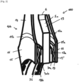
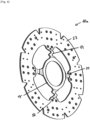
- the shock absorber 100 may comprise a first friction device 10a comprising a first friction washer 11a.
- the first friction washer 11a may be provided with two single fixing portions 12 rigidly fixed in rotation on the first element 1 or the second element. More particularly, each of the two fixing portions 12 may be fixed on the support element 13 of the intermediate disc 1a. Alternatively, each of the two fixing portions 12 may be fixed on the support element 13 of the first lateral washer or the second lateral washer.
- the first friction washer 11a has a friction portion 15.
- the friction portion 15 may have a friction track 16 and a back face 17.
- Each of the two fixing portions 12 of the first friction washer 11a can be connected to the friction portion 15 by a flexible element 14 allowing axial movement of the dorsal face 17 relative to the first element 1.
- rotational locking can be achieved between the first element and the first friction washer 11a, without angular play, while allowing movement of the dorsal face 17 of the friction portion 15 relative to the first element 1, which makes it possible to compensate for wear on the friction surfaces.
- the flexible element 14 may be a flexible tab. It may be formed in one piece with the friction portion 15 and the fixing portion 12. Thus, the first friction washer 11a is advantageously manufactured from a single sheet.
- Each support element 13 and each fixing portion 12 may each comprise at least one orifice 21.
- Each fixing portion orifice 12 is arranged opposite a support element orifice 13.
- Each fixing portion 12 can thus be fixed rigidly in rotation to the corresponding support element 13 by means of at least one fixing element, such as a rivet 20.
- Each fixing portion 12 is also axially locked on the support element 13 by means of the rivets 20.
- the friction portion 15 is formed on a radially inner portion of the first friction washer 11a and each fixing portion 12 is formed on a radially outer portion of the first friction washer 11a.
- the clutch disc may further comprise springs.
- the springs may be helical springs which extend circumferentially or tangentially around the X axis over a mean implantation radius.
- the fixing portions 12 are arranged radially outside the mean implantation radius.
- the mean implantation radius is taken at the middle zone of the length of a spring, and at the main axis around which the turns of the spring are wound.
- the first friction washer 11a may comprise two single fixing portions 12 and the first element 1 or the second element may comprise a plurality of support elements 13, a part of the support elements 13 receiving a fixing portion 12.
- Each flexible leg 14 is axially elastically deformable.
- the first friction device 10a may further comprise a first elastic washer 18a.
- the first elastic washer 18a may be arranged axially between the first element 1 and the first friction washer 11a. More particularly, the first elastic washer 18a may be arranged axially between the intermediate disc 1a and the back face 17 of the friction portion 15.
- the first elastic washer 18a is arranged axially between the intermediate disc 1a and the back face 17 of the friction portion 15 of the first friction washer 11a, to axially press the friction portion 15 against a friction surface of the first side washer.
- the first elastic washer 18a may be a single piece.
- the first elastic washer 18a may be continuous and extend circumferentially.
- the first elastic washer 18a may have a corrugated shape.
- the corrugated shape has, radially, a succession of zones axially offset two by two.
- the first friction device 10a may further comprise a first shim washer 30a.
- the first shim washer 30a may comprise a continuous, circumferentially extending main body.
- the first shim washer 30a may comprise a plurality of tabs 31 extending axially from the main body.
- the plurality of tabs 31 may be adapted to hold the first elastic washer 18a.
- the first shim washer 30a may be arranged axially between the first element 1 and the first friction washer 11a. More particularly, the first shim washer 30a may be arranged axially between the first element 1 and the first elastic washer 18a.
- Each flexible leg 14, the first elastic washer 18a and the first shim washer 30a may be configured such that, in operation, for at least one compression state of the first elastic washer 18a, an axial load is exerted by each flexible leg 14 in a direction opposite to the direction of the load exerted by the first elastic washer 18a on the friction portion 15.
- the flexible legs 14 and the first spring washer 18a may be configured so that the load exerted by the first spring washer 18a remains greater than the load exerted by the flexible legs 14 of the first friction washer 11a.
- the compression state of the first elastic washer 18a may depend on the initial preload of the first elastic washer 18a and the wear state of the first friction device 10a.
- the two single fixing portions 12 may be arranged at 180 degrees to each other. Alternatively, the two single fixing portions may be arranged between 50 and 110 degrees to each other, preferably at 90 degrees to each other.
- each flexible leg 14 may be arranged circumferentially between two springs.
- the first element 1 may comprise openings for housing the springs, and each support element 13 is arranged circumferentially between two neighboring openings.
- the friction portion 15 may be composed of a single friction plate.
- the friction plate may extend circularly around the X axis.
- the friction plate may be continuous.
- the friction portion 15 may be composed of a plurality of friction pads spaced apart from each other. Each friction pad 15 may be associated with a single flexible tab 14.
- the friction portion 15 forms a radially internal ring of the first friction washer 11a which extends around the axis X of rotation and develops radially.
- the first friction washer 11a may further comprise a radially outer ring 23 and each flexible tab 14 connects the friction portion 15 and the radially outer ring 23.
- the radially outer ring 23 extends around the axis X of rotation and expands radially.
- the fixing portions 12, the flexible tabs 14, the friction portion 15 and the radially external ring 23 can be formed in a single piece from a cut sheet metal.
- a space may be present between two neighboring flexible legs 14, in particular to allow the arrangement of a spring.
- the flexible legs 14 are each arranged between two springs.
- the radially outer ring 23 is arranged against a radially outer edge of the first element 1.
- Each attachment portion 12 may be formed on a flare that extends the flexible leg 14 and connects the flexible leg 14 to the ring radially external 23.
- Each fixing portion 12 can be arranged to receive two rivets 20.
- the first friction washer may comprise a plurality of fixing portions 12.
- the plurality is at least three fixing portions 12.
- Each flexible tab 14 connecting the fixing portions 12 to the friction portion 15 may be corrugated.
- Each corrugated flexible tab 14 may have, radially, a succession of zones axially offset two by two.
- the shock absorber may comprise an even number n of springs, for example four, interposed circumferentially between the intermediate disc 1a and the second element.
- the first friction washer 11a may comprise n fixing portions 12, for example four, and n flexible elements, for example four. Thus, it is possible to have a first friction washer 11a with less axial stiffness.
- Each fixing portion 12 may be arranged circumferentially between two neighboring springs.
- the damper 100 may further comprise a second friction device 10b.
- the second friction device 10b may be independent of the first friction device 10a.
- the second friction device 10b is adapted to undergo, independently of the first friction device 10a, the axial movements linked to the passage of the engine torque.
- the second friction device 10b comprises a second friction washer 11b.
- the second friction washer 11b may be identical to the first friction washer 11a.
- the first friction washer 11a and the second friction washer 11b may be positioned in central symmetry with respect to each other with respect to the first element 1.
- the second friction device 10b may further comprise a second elastic washer 18b.
- the second elastic washer 18b may be identical to the first elastic washer 18a.
- the first elastic washer 18a and the second elastic washer 18b may be positioned in central symmetry with respect to each other with respect to the first element 1.
- the second elastic washer 18b makes it possible to axially press the second friction washer 11b independently with respect to the first friction washer 11a.
- the second friction device 10b may further comprise a second shim washer 30b.
- the second shim washer 30b may be identical to the first shim washer 30a.
- the first shim washer 30a and the second shim washer 30b may be positioned in central symmetry with respect to each other with respect to the first element 1.
Landscapes
- Engineering & Computer Science (AREA)
- General Engineering & Computer Science (AREA)
- Mechanical Engineering (AREA)
- Physics & Mathematics (AREA)
- Acoustics & Sound (AREA)
- Aviation & Aerospace Engineering (AREA)
- Mechanical Operated Clutches (AREA)
Applications Claiming Priority (1)
| Application Number | Priority Date | Filing Date | Title |
|---|---|---|---|
| FR2315554A FR3157909A1 (fr) | 2023-12-31 | 2023-12-31 | Amortisseur de torsion et disque d’embrayage. |
Publications (1)
| Publication Number | Publication Date |
|---|---|
| EP4579098A1 true EP4579098A1 (de) | 2025-07-02 |
Family
ID=93011007
Family Applications (1)
| Application Number | Title | Priority Date | Filing Date |
|---|---|---|---|
| EP24220818.9A Pending EP4579098A1 (de) | 2023-12-31 | 2024-12-17 | Torsionsdämpfer und kupplungsscheibe |
Country Status (4)
| Country | Link |
|---|---|
| US (1) | US20250215955A1 (de) |
| EP (1) | EP4579098A1 (de) |
| CN (1) | CN120231852A (de) |
| FR (1) | FR3157909A1 (de) |
Citations (4)
| Publication number | Priority date | Publication date | Assignee | Title |
|---|---|---|---|---|
| US4573945A (en) * | 1983-12-22 | 1986-03-04 | Kabushiki Kaisha Daikin Seisakusho | Damper disc of a long travel type |
| DE29924341U1 (de) * | 1998-07-17 | 2002-10-24 | ZF Sachs AG, 97424 Schweinfurt | Kupplungsscheibe für eine Kraftfahrzeug-Reibungskupplung |
| DE102020202324A1 (de) * | 2019-03-28 | 2020-10-01 | Zf Friedrichshafen Ag | Kupplungsscheibe, Reibeinrichtung und Reibring für eine Reibeinrichtung |
| US20220178421A1 (en) * | 2019-03-29 | 2022-06-09 | Valeo Embrayages | Torsion damper and clutch disk |
-
2023
- 2023-12-31 FR FR2315554A patent/FR3157909A1/fr active Pending
-
2024
- 2024-12-17 EP EP24220818.9A patent/EP4579098A1/de active Pending
- 2024-12-23 US US18/999,574 patent/US20250215955A1/en active Pending
- 2024-12-30 CN CN202411969737.4A patent/CN120231852A/zh active Pending
Patent Citations (4)
| Publication number | Priority date | Publication date | Assignee | Title |
|---|---|---|---|---|
| US4573945A (en) * | 1983-12-22 | 1986-03-04 | Kabushiki Kaisha Daikin Seisakusho | Damper disc of a long travel type |
| DE29924341U1 (de) * | 1998-07-17 | 2002-10-24 | ZF Sachs AG, 97424 Schweinfurt | Kupplungsscheibe für eine Kraftfahrzeug-Reibungskupplung |
| DE102020202324A1 (de) * | 2019-03-28 | 2020-10-01 | Zf Friedrichshafen Ag | Kupplungsscheibe, Reibeinrichtung und Reibring für eine Reibeinrichtung |
| US20220178421A1 (en) * | 2019-03-29 | 2022-06-09 | Valeo Embrayages | Torsion damper and clutch disk |
Also Published As
| Publication number | Publication date |
|---|---|
| US20250215955A1 (en) | 2025-07-03 |
| CN120231852A (zh) | 2025-07-01 |
| FR3157909A1 (fr) | 2025-07-04 |
Similar Documents
| Publication | Publication Date | Title |
|---|---|---|
| FR2694356A1 (fr) | Volant d'inertie à deux masses. | |
| EP0738378A1 (de) | Torsionsschwingungsdämpfer, insbesondere mit reibung der kuppling für kraftfahrzeuge | |
| FR2794832A1 (fr) | Double volant amortisseur pour vehicule automobile | |
| FR2757231A1 (fr) | Disque d'embrayage pour un vehicule automobile | |
| FR2710385A1 (fr) | Amortisseur de torsion. | |
| FR2594191A1 (fr) | Embrayage a friction | |
| FR2539194A1 (fr) | Disque d'embrayage, notamment pour vehicule automobile | |
| EP3948001B1 (de) | Torsionsdämpfer und kupplungsscheibe | |
| FR2750751A1 (fr) | Ensemble formant disque amortisseur | |
| FR2644538A1 (fr) | Amortisseur de torsion, en particulier double volant amortisseur pour vehicule automobile | |
| FR3157909A1 (fr) | Amortisseur de torsion et disque d’embrayage. | |
| FR2894637A1 (fr) | Dispositif de friction perfectionne pour un embrayage, notamment de vehicule automobile | |
| WO2005071279A1 (fr) | Embrayage a friction, notamment pour vehicule automobile, comportant des moyens de frottement differencies. | |
| EP3839282B1 (de) | Progressivitätsgerät für eine reibkupplungsscheibe und eine reibungskupplungsscheibe, die ein solches gerät enthält | |
| FR2969730A1 (fr) | Organe de phasage pour un amortisseur de torsion | |
| EP3889459B1 (de) | Reibscheibe für torsionsdämpfer | |
| FR2816679A1 (fr) | Dispositif de transmission de couple, en particulier pour vehicule automobile | |
| FR2843785A1 (fr) | Disque d'embrayage | |
| FR2845141A1 (fr) | Amortisseur de torsion, notamment d'embrayage pour vehicule automobile | |
| FR2920500A1 (fr) | Disque porte-garnitures, notamment pour un disque de friction d'embrayage de vehicule automobile. | |
| WO2010040933A1 (fr) | Embrayage a friction a amortisseur symetrique, notamment pour vehicule automobile, comprenant des moyens d'amortissement differencies | |
| FR2769057A1 (fr) | Ensemble formant disque d'embrayage muni de plaques d'amortissement | |
| FR2728642A1 (fr) | Amortisseur de torsion, notamment friction d'embrayage pour vehicule automobile | |
| FR2765936A1 (fr) | Ensemble amortisseur dynamique et ensemble formant volant comportant un tel ensemble amortisseur | |
| FR2785957A1 (fr) | Amortisseur de torsion pour disque d'embrayage a friction |
Legal Events
| Date | Code | Title | Description |
|---|---|---|---|
| PUAI | Public reference made under article 153(3) epc to a published international application that has entered the european phase |
Free format text: ORIGINAL CODE: 0009012 |
|
| STAA | Information on the status of an ep patent application or granted ep patent |
Free format text: STATUS: EXAMINATION IS IN PROGRESS |
|
| 17P | Request for examination filed |
Effective date: 20241217 |
|
| AK | Designated contracting states |
Kind code of ref document: A1 Designated state(s): AL AT BE BG CH CY CZ DE DK EE ES FI FR GB GR HR HU IE IS IT LI LT LU LV MC ME MK MT NL NO PL PT RO RS SE SI SK SM TR |