EP4579103A1 - Verbindungsanordnung zur unterstützung einer materialschicht, die über einen bewegungsbereich eine konstante länge beibehält - Google Patents
Verbindungsanordnung zur unterstützung einer materialschicht, die über einen bewegungsbereich eine konstante länge beibehält Download PDFInfo
- Publication number
- EP4579103A1 EP4579103A1 EP24220898.1A EP24220898A EP4579103A1 EP 4579103 A1 EP4579103 A1 EP 4579103A1 EP 24220898 A EP24220898 A EP 24220898A EP 4579103 A1 EP4579103 A1 EP 4579103A1
- Authority
- EP
- European Patent Office
- Prior art keywords
- linkage
- linkages
- pin
- material layer
- slot
- Prior art date
- Legal status (The legal status is an assumption and is not a legal conclusion. Google has not performed a legal analysis and makes no representation as to the accuracy of the status listed.)
- Pending
Links
Images


Classifications
-
- F—MECHANICAL ENGINEERING; LIGHTING; HEATING; WEAPONS; BLASTING
- F16—ENGINEERING ELEMENTS AND UNITS; GENERAL MEASURES FOR PRODUCING AND MAINTAINING EFFECTIVE FUNCTIONING OF MACHINES OR INSTALLATIONS; THERMAL INSULATION IN GENERAL
- F16H—GEARING
- F16H21/00—Gearings comprising primarily only links or levers, with or without slides
- F16H21/10—Gearings comprising primarily only links or levers, with or without slides all movement being in, or parallel to, a single plane
- F16H21/44—Gearings comprising primarily only links or levers, with or without slides all movement being in, or parallel to, a single plane for conveying or interconverting oscillating or reciprocating motions
-
- B—PERFORMING OPERATIONS; TRANSPORTING
- B65—CONVEYING; PACKING; STORING; HANDLING THIN OR FILAMENTARY MATERIAL
- B65D—CONTAINERS FOR STORAGE OR TRANSPORT OF ARTICLES OR MATERIALS, e.g. BAGS, BARRELS, BOTTLES, BOXES, CANS, CARTONS, CRATES, DRUMS, JARS, TANKS, HOPPERS, FORWARDING CONTAINERS; ACCESSORIES, CLOSURES, OR FITTINGS THEREFOR; PACKAGING ELEMENTS; PACKAGES
- B65D21/00—Nestable, stackable or joinable containers; Containers of variable capacity
- B65D21/08—Containers of variable capacity
- B65D21/086—Collapsible or telescopic containers
-
- B—PERFORMING OPERATIONS; TRANSPORTING
- B60—VEHICLES IN GENERAL
- B60B—VEHICLE WHEELS; CASTORS; AXLES FOR WHEELS OR CASTORS; INCREASING WHEEL ADHESION
- B60B19/00—Wheels not otherwise provided for or having characteristics specified in one of the subgroups of this group
- B60B19/04—Wheels not otherwise provided for or having characteristics specified in one of the subgroups of this group expansible
-
- B—PERFORMING OPERATIONS; TRANSPORTING
- B63—SHIPS OR OTHER WATERBORNE VESSELS; RELATED EQUIPMENT
- B63B—SHIPS OR OTHER WATERBORNE VESSELS; EQUIPMENT FOR SHIPPING
- B63B1/00—Hydrodynamic or hydrostatic features of hulls or of hydrofoils
- B63B1/16—Hydrodynamic or hydrostatic features of hulls or of hydrofoils deriving additional lift from hydrodynamic forces
- B63B1/24—Hydrodynamic or hydrostatic features of hulls or of hydrofoils deriving additional lift from hydrodynamic forces of hydrofoil type
- B63B1/28—Hydrodynamic or hydrostatic features of hulls or of hydrofoils deriving additional lift from hydrodynamic forces of hydrofoil type with movable hydrofoils
-
- B—PERFORMING OPERATIONS; TRANSPORTING
- B64—AIRCRAFT; AVIATION; COSMONAUTICS
- B64C—AEROPLANES; HELICOPTERS
- B64C3/00—Wings
- B64C3/38—Adjustment of complete wings or parts thereof
-
- B—PERFORMING OPERATIONS; TRANSPORTING
- B64—AIRCRAFT; AVIATION; COSMONAUTICS
- B64C—AEROPLANES; HELICOPTERS
- B64C5/00—Stabilising surfaces
- B64C5/10—Stabilising surfaces adjustable
Definitions
- the reconfigurable structure can provide a first configuration corresponding to a curved or annular tube shape for a fluid vessel, conduit, or other suitable structure, and a second configuration corresponding to a flattened shape.
- the flattened shape of the second configuration can be used for storage and transport of the reconfigurable structure.
- a linkage assembly includes a plurality of linkages.
- the linkage assembly can form part of a reconfigurable structure, such as a fluid vessel configured to hold or transport a fluid in a liquid phase, vapor phase and/or gas phase, a conduit, an airfoil, a hydrofoil, a control surface, a wheel or other suitable structure.
- Linkages of the linkage assembly can be rotatably coupled to each other in a manner that enables a material layer mounted to an exterior edge of the linkage assembly to maintain a constant length across a range of motion of the linkages.
- in-plane strain within the material layer can be reduced or eliminated.
- This configuration enables the material layer to be formed from materials having a relatively high modulus of elasticity, such as metals including aluminum and steel, as examples.
- a plurality of linkages of the linkage assembly includes at least a pair of linkages that are rotatably coupled to each other via a hinge formed by a first pin-in-slot joint and a second pin-in-slot j oint.
- the first pin-in-slot joint includes a first curved slot formed within a (first) linkage of the pair of linkages and a first pin of another (second) linkage of the pair of linkages that is retained within the first curved slot.
- the second pin-in-slot joint includes a second curved slot formed within the (first) linkage of the pair of linkages and a second pin of another (second) linkage of the pair of linkages that is retained within the second curved slot.
- the hinge formed by the first pin-in-slot j oint and the second pin-in-slot j oint takes the form of a virtual joint having a virtual pivot located on the material layer, enabling the material layer to maintain a constant length across a range of motion of the linkages.
- the disclosed linkage assemblies and reconfigurable structures offer the potential to address various issues. For example, within the context of fluid vessels such as fuel tanks, existing fuel tanks compatible with high acceleration aircraft are not able to be stowed in a flattened configuration when not deployed and thus occupy significant volume during storage and transport.
- the disclosed linkage assemblies and reconfigurable structures e.g., a fluid vessel
- the disclosed reconfigurable structures can be flat packed for storage and transport when not deployed for use.
- the reconfigurable structures disclosed herein can provide a range of aerodynamic or hydrodynamic performance characteristics through rotation or manipulation of the various linkages that support the material layer.
- the reconfigurable structures disclosed herein can take the form of a wheel that can be deployed for use on a vehicle, while also enabling the wheel to be flattened for storage and transport.
- the material layer can maintain a constant length across a range of motion of the linkages, thereby enabling an expanded range of materials from which the material layer can be formed.
- the example linkage assemblies disclosed herein can include linkages having a repeating configuration, enabling the linkages to be manufactured using the same techniques and tooling.
- FIG. 1 depicts an example linkage assembly 100 that includes a plurality of linkages 102.
- the plurality of linkages 102 includes at least a pair of linkages 104 rotatably coupled to each other that form part of a linkage chain 106.
- first linkage 110-1 and second linkage 110-2 of the pair of linkages 104 are neighboring linkages of linkage chain 106.
- the plurality of linkages 102 can include additional linkages rotatably coupled to each other to form linkage chain 106 in combination with the pair of linkages 104.
- Linkage assembly 100, including the pair of linkages 104 can form part of a reconfigurable structure in combination with one or more other linkages, such as described with reference to FIGS. 4 , 6 , 13, and 14 as examples.
- first linkage 110-1 and second linkage 110-2 are rotatably coupled to each other via a hinge 103-1.
- Hinge 103-1 enables first linkage 110-1 and second linkage 110-2 to rotate relative to each other within a plane of rotation 116 to provide different configurations of linkage assembly 100, as described in further detail with reference to FIGS. 2 and 3 .
- First linkage 110-1, second linkage 110-2, and other linkages of linkage chain 106 can each refer to an instance of a linkage configuration 110, an example of which is depicted in FIG. 1 .
- some or all of the linkages of linkage chain 106, including first linkage 110-1 and second linkage 110-2 each have the same shape and features as linkage configuration 110. Accordingly, aspects of the various linkages disclosed herein are at times described in further detail herein with reference to linkage configuration 110.
- angle 172 and angle 156 can be equal but orientated in opposing directions to provide a symmetrical configuration about a midplane 174 of linkage configuration 110', shown with dashed lines, that is orthogonal to axis 154.
- linkage configuration 110' has a second pair of curved slots 120' and 124' in place of circular openings 119 and 123 that are used to retain respective pins of a neighboring linkage. Examples of linkage configuration 110' are described in further detail with reference to FIG. 4 .
- linkage configurations 110 and 110' define openings or cutouts located away from slots 120 and 124, and away from pin openings 119 and 123 that decrease the mass of the linkage while maintaining sufficient structural integrity.
- the quantity and configuration of such openings and cutouts is application dependent.
- FIG. 2 depicts linkage assembly 100 of FIG. 1 in which the pair of linkages 104 of the linkage assembly have a first configuration 200, as previously depicted in FIG.
- the orientation and spacing of curved slots 120-1 and 124-1 relative to each other, including the location of first terminal ends 126-1 and 128-1 defines the angle (e.g., 158 of FIG. 1 ) at which second linkage 110-2 is rotated relative to second linkage 110-1 in first configuration 200.
- FIG. 2 further depicts linkage assembly 100 including a material layer 210 that is mounted to and supported by first linkage 110-1 and second linkage 110-2.
- material layer 210 forms a first shape 214.
- the first shape 214 of material layer 210 is a convex shape (curved shape) in first configuration 200 of FIG. 2 .
- Material layer 210 can take the form of and be referred to as a membrane or skin.
- Material layer 210 in this example, extends along at least a portion of exterior edge 146, including at least exterior edge portions 150-1 and 152-1 of first linkage 110-1, and exterior edge portions 150-2 and 152-2 of second linkage 110-2. Additionally, material layer 210 spans a boundary 212 between first linkage 110-1 and second linkage 110-2.
- material layer 210 is mounted directly to first linkage 110-1 and second linkage 110-2 along at least a portion of exterior edge 146, including exterior edge portions 150-1 and 152-1 of first linkage 110-1, and exterior edge portions 150-2 and 152-2 of second linkage 110-2. Additionally or alternatively, as described herein, material layer 210 can be mounted to first linkage 110-1 and second linkage 110-2 via an intermediate structure (e.g., as shown in FIG. 15 ). In each of these examples, common radius center 142-1 and virtual pivot 144-1 can be located on or within material layer 210 so that the length of the material layer is maintained across the range of motion of the linkage assembly, thereby reducing or eliminating in-plane strain within the material layer.
- FIG. 2 schematically depicts a detailed view of material layer 210 at 220 in which common radius center 142-1 and virtual pivot 144-1 are located within the material layer.
- common radius center 142-1 and virtual pivot 144-1 are located on centerline 222 of material layer 210.
- common radius center 142-1 and virtual pivot 144-1 are located on an exterior surface of material layer 210. In-plane strain within material layer 210 may increase as common radius center 142-1 and virtual pivot 144-1 are moved away from the centerline of the material layer.
- the configuration of hinge 103-1, including the configuration of slots 120-1 and 124-1 can be designed with respect to the location of material layer 210.
- the configuration of slots 120-1 and 124-1 can be changed so that common radius center 142 and virtual pivot 144 are located on or within material layer 210 (e.g., one or near the centerline of the material layer).
- material layer 210 As a constant length of material layer 210 is maintained across the range of motion of the linkage assembly, the material layer need not stretch in-plane. Accordingly, material layer 210 can be formed from a material, such as metal (e.g., aluminum, steel, etc.) that exhibits a relatively high modulus of elasticity. Additionally, through use of the disclosed configuration of hinge 103-1, material layer 210 need not undergo deformation in-plane due to rotation of first linkage 110-1 relative to second linkage 110-2.
- metal e.g., aluminum, steel, etc.
- FIG. 3 depicts linkage assembly 100 of FIG. 1 in which the pair of linkages 104 of linkage assembly 100 have a second configuration 300.
- Second configuration 300 of FIG. 3 differs from first configuration 200 of FIG. 2 due to rotation and translation of second linkage 110-2 relative to first linkage 110-1.
- exterior edge portion 150-1 of first linkage 110-1 and exterior edge portion 150-2 of second linkage 110-2 are colinear with each other and axis 154, thereby forming a planar (flattened) configuration of exterior edge 146.
- first pin 118-1 of first pin-in-slot joint 112-1 is located at second terminal end 126-2 of first curved slot 120-1
- second pin 122-1 of second pin-in-slot joint 114-1 is located at second terminal end 128-2 of second curved slot 124-1. Locating the pins at the second terminal end of the curved slots in the second configuration 300 enables the linkage assembly to provide and maintain a rigid state in the second configuration when 110-2 is loaded with a counterclockwise torque against fixed 110-1.
- FIG. 3 depicts a rotation angle 316 by which first linkage 110-1 and second linkage 110-2 are rotated relative to each other via hinge 103 between first configuration 200 of FIG. 2 and second configuration 300 of FIG. 3 .
- a magnitude of rotation angle 316 is equal to each of angles 158, 160, and the angular displacement defined by curved slots 120 and 124, as previously described with reference to FIG. 1 .
- first linkage 110-1 and second linkage 110-2 are rotated relative to each other via hinge 103 between first configuration 200 of FIG. 2 and second configuration 300 of FIG. 3 , the first linkage and the second linkage also translate relative to each other by a translation distance 318.
- translation distance 318 is equal to a length of the circular arc segments of curved slots 120-1 and 124-1 (as measured between their respective pin locations at the terminal ends of the curved slots).
- hinge 103-1 formed by first pin-in-slot joint 112-1 and second pin-in-slot joint 114-1 enables rotation and translation of first linkage 110-1 and second linkage 110-2 relative to each other.
- first pin 118-1 and second pin 122-1 are aligned with and reside along axis 162 that is parallel to axis 154, thereby configuring exterior edge 146 of the pair of linkages 104 along the same plane such that exterior edge components 150-1 and 150-2 are colinear.
- first pin-in-slot joint 112-1 and second pin-in-slot joint 114-1 of hinge 103-1 constrain movement in the form of rotation and translation of first linkage 110-1 and second linkage 110-2 relative to each other, hinge 103-1 can be characterized as providing a single degree of freedom with respect to first linkage 110-1 and second linkage 110-2.
- first pin 118-1 and second pin 122-1 are aligned with and reside along axis 162 that is parallel to axis 154, thereby configuring exterior edge 146 of the pair of linkages 104 along a s.
- a location of pins of another neighboring linkage that may be retained within each of curved slots 120-2 and 124-2 of second linkage 110-2 at second terminal ends 326-2 and 328-2, respectively, are also aligned with and reside along axis 162, thereby enabling an exterior edge portion of the neighboring linkage to be colinear with axis 154, as described with reference to FIG. 6 .
- Material layer 210 forms a second shape 314 in second configuration 300 that differs from first shape 214 of FIG. 2 .
- the second shape 314 of material layer 210 is a planar shape (flat shape) in second configuration 300. While the first shape 214 and the second shape 314 of material layer 210 differ from each other (e.g., have different curvature), a length of material layer 210 remains constant throughout a range of motion between first configuration 200 and second configuration 300. Accordingly, material layer 210 experiences reduced or zero in-plane strain due to reconfiguration of linkage assembly 100 between first configuration 200 and second configuration 300.
- second configuration 300 may instead provide an angle between exterior edge portion 150-1 of first linkage 110-1 and exterior edge portion 150-2 of second linkage 110-2 that differs from the angle (e.g., 158) in first configuration 200.
- curved slots 120-1 and 124-1 can be extended, shortened, or otherwise reconfigured to provide any suitable angle between first linkage 110-1 and second linkage 110-2 in first and second configurations.
- section 212 is the portion of material layer 210 that is not in direct contact with exterior edges 150-1 and 150-2 of linkages 110-1 and 110-2 respectively that flexes when joint 103-1 actuates between configurations 200 and 300.
- Section 212 is always unsupported by the linkages so that the pivot can actuate. In most embodiments of this mechanism, unsupported section 212 is a critical weak point in the outer material layer that drives many of the other design considerations.
- the only suitable region for attaching layer material layer 210 to the various instances of linkages 110 is at instances of edge portion 150.
- Edge 150 is the only portion of 110 across which the material layer 210 remains stationary relative to linkage 110 during actuation between the two configurations of the linkage assembly.
- FIG. 4 depicts another example linkage assembly 400 that includes the pair of linkages 104 of FIG. 1 as a sub-assembly of linkage assembly 400.
- the pair of linkages 104 including first linkage 110-1 and second linkage 110-2 are rotated relative to each other about hinge 103-1 to provide first configuration 200 of FIG. 2 .
- hinge 103-1 of the pair of linkages 104 is formed by first pin-in-slot joint 112-1 and second pin-in-slot joint 114-1 that work together to allow the linkages to pivot about common radius center 142-1 and virtual pivot 144-1 located on or within the material layer.
- Linkage assembly 400 includes additional repeated instances of linkage configurations 110 and 110' of FIG. 1 that are rotatably coupled to each other via hinges that have the same configuration as hinge 103-1.
- Each instance of hinge 103-1 within linkage assembly 400 can also have a common radius center and virtual pivot that are located on or within the material layer (e.g., on a centerline of the material layer).
- the various linkages of linkage assembly 400 collectively form an annular shape 402 that encloses an interior region 410.
- linkage assembly 400 can take the form of a structural rib of a reconfigurable structure, such as a fluid vessel (e.g., water tank, fuel tank, etc.), a conduit, or a wheel, additional examples of which are described with reference to FIGS. 8 , 9 , 10 , 11 , and 12 .
- a fluid vessel e.g., water tank, fuel tank, etc.
- conduit e.g., a conduit, or a wheel
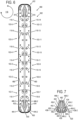
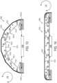
- FIG. 8 depicts an example reconfigurable structure 800 that includes multiple instances of linkage assembly 400 of FIG. 4 that are identified by reference numerals 400-1, 400-2, 400-3, and 400-4.
- Reconfigurable structure 800 has a first configuration corresponding to an annual tube shape in FIG. 8 .
- reconfigurable structure 800 takes the form of a fluid vessel, aspects of which are described in further detail with reference to FIGS. 9-11 .
- a continuous structural wall could be formed by stacking many instances of linkage assembly 400 side-by-side without changing or affecting kinematic properties of the linkage assemblies.
- These linkage stacks do not have to contain the same number of linkages and they increase in strength in direct proportion to the number of links in that stack.
- the ability to stack linkages enables the designer of the reconfigurable structure to tailor the strength of each stack to the loads and stresses in that part of the structure without adding unnecessary mass and cost.
- a structure for containing a fluid may exhibit greatest stress at the bottom of the structure due to gravity, in such case it can be advantageous to place the largest stacks at the bottom of the structure.
- Linkage assemblies 400-1, 400-2, 400-3, and 400-4 are retained in alignment with each other along longitudinal axis 802 by longitudinal supports or stringers 810 that pass through openings 470 in the linkage assemblies. Additionally, each of linkage assemblies 400-1, 400-2, 400-3, and 400-4 are retained in the annular shape 402 of FIG. 4 by rigid connections at the top and bottom with a common spine 460 that spans across each and all of the linkage assemblies.
- spine 460 includes openings 820 that serve as mass-saving cut outs in addition to enabling fluid contained within an interior region bounded by material layer 480 to migrate between opposing sides of the spine. Note that the rectangular geometry of each opening 820 is depicted for purposes of discussion and ease of illustration, and that these openings can have other suitable shapes (e.g., trusses) that distribute stress.
- Reconfigurable structure 800 includes a second end support plate 910-2 that is identical to or similarly configured as first end support plate 910-1 installed on a second terminal end 914 of the annular tube shape formed by material layer 480.
- This configuration allows for tensile load to be transferred between opposing support plates 910-1 and 910-2 via the stringers 810 to avoid applying stress to the linkage assemblies (e.g., 400-1, 400-2, 400-3, and 400-4).
- linkage assemblies e.g., 400-1, 400-2, 400-3, and 400-4.
- end support plates 910-1 and 910-2 can provide additional support for the linkage assemblies to maintain the annular shape 402 depicted in FIG.
- End support plates 910-1 and 910-2 support the interior of material layer 480 at and along the distal ends of the tube so that the material layer can be loaded on its exterior by end caps. This allows for the material layer 480 to be pitched in the radial direction between the end support plates on an interior side and the end caps on the exterior side so that a fluid tight barrier can be achieved on this seem. This feature enables potential applications as a deployable closed volume where there is a large pressure difference between the interior and the exterior of the volume such as for transporting pressurized gases or creating a large deployable water storage tank for disaster relief.
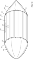
- FIG. 10 depicts reconfigurable structure 800 including an end cap 1010 installed on first terminal end 912, and an end cap 1012 installed on second terminal end 914 of the annular tube formed by material layer 480.
- end caps 1010 and 1012 take the form of aerodynamic nose and tail cones, respectively.
- reconfigurable structure 800 can take the form of a fluid vessel 1000, such as a drop tank that can be carried upon an aircraft or other aeronautical vehicle.
- longitudinal supports or stringers 810 pass through openings formed within end caps 1010 and 1012. Terminal ends of the longitudinal supports or stringers 810 can include threads that accommodate a threaded nut or other fastener to enable end caps 1010 and 1012 to be tightened against first end support plate 910-1 and second end support plate 910-2, respectively. Seals can be included at an interface between the end caps (1010, 1012) and end support plates (910-1, 910-2), between the end caps and material layer 480, and between the end support plates and the material layer. Aerodynamic plugs can be added over recessed bolt heads in end caps to maintain a smooth exterior.
- fluid vessel 1000 can include an opening and cap represented schematically at 1022 that enables a fluid to be provided to or retrieved from an interior of the fluid vessel.
- fluid vessel 1000 can include a mounting structure 1024 represented schematically in FIG. 10 that enables the fluid vessel to be mounted to another structure, such as an aircraft or other aeronautical vehicle, as an example. Providing an opening in location 1024 for a mounting structure can be advantageous because it enables for a direct interface with central spine 460.
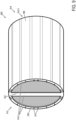
- FIG. 11 depicts another example of reconfigurable structure 800 including an end cap 1110 installed on first terminal end 912, and an end cap 1112 installed on second terminal end 914 of the annular tube shape formed by material layer 480.
- end caps 1010 and 1012 have a flat or planar configuration in contrast to the aerodynamic nose and tail cones of FIG. 10 .
- reconfigurable structure 800 can take the form of a fluid storage container or barrel 1100.
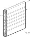
- FIG. 12 depicts reconfigurable structure 800 of FIG. 8 in a second configuration in which the reconfigurable structure has been collapsed to a flattened shape, as previously described with reference to FIG. 6 .
- the flattened shape of reconfigurable structure 800 occupies less volume than the annular tube shape of FIGS. 8 - 11 , enabling the reconfigurable structure to be flat-packed for storage and transport, as an example.
- spine 460 of FIG. 8 end support plates 910-1 and 910-2 of FIG. 9 , and end caps 1010 and 1012 of FIG. 10 or 111 and 1112 of FIG. 11 have been removed to enable reconfigurable structure 800 to be collapsed to the flattened shape.
- Spine 460, end support plates 910-1 and 910-2, and end caps 1110 and 1112, each having a flat or planar configuration can be flat packed with reconfigurable structure 800 for storage and transport.
- FIG. 13 depicts another example of a reconfigurable structure 1300 that can take the form of at least a portion of an airfoil, a hydrofoil, or a control surface, as examples.
- Reconfigurable structure 1300 includes one or more instances of linkage assembly 1310 that are spaced apart from each other along a longitudinal axis that is orthogonal to plane of rotation 116.
- linkage assembly 1310 includes a linkage chain 1312 formed by linkages 110-1, 110-2, 110-3, 110-4, and 110-5 having the same configuration as previously described with reference to FIG. 4 .
- the linkages of linkage chain 1312 of linkage assembly 1310 are rotatably coupled to each other via hinges 103-1, 103-2, 103-3, and 103-4 in which each hinge is formed by a pair of pin-in-slot joints.
- linkage assembly 1310 has a first configuration corresponding to a convex shape (curved shape) in which each linkage of linkage chain 1312 is rotated at an angle relative to its neighboring linkage(s), as previously described with reference to FIG. 2 . While linkage chain 1312 includes five linkages in this example, it will be understood that linkage chain 1312 can include any suitable quantity of linkages.
- Linkage assembly 1310 further includes a first base linkage sub-assembly 1314-1 and a second base linkage sub-assembly 1314-2 located at opposing terminal ends of linkage chain 1312.
- linkage 110-1 is rotatably coupled to first base linkage sub-assembly 1314-1
- linkage 110-5 is rotatably coupled to second base linkage sub-assembly 1314-2.
- First base linkage sub-assembly 1314-1 and second base linkage sub-assembly 1314-2 have a configuration that is similar to previously described base linkage sub-assemblies 420 and 422 of FIGS. 4-7 with respect to first linkage chain 412.
- Reconfigurable structure 1300 further includes a material layer 1316 that is mounted to and supported by the linkages of linkage assembly 1310, as previously described with reference to FIGS. 1-4 .
- Reconfigurable structure 1300 can further include one or more actuators 1320, represented schematically in FIG. 13 .
- the one or more actuators 1320 are operable to move reconfigurable structure 1300 between the first configuration of FIG. 13 and a second configuration of FIG. 14 corresponding to a flattened shape of the reconfigurable structure.
- FIG. 14 depicts reconfigurable structure 1300 of FIG. 13 having a second configuration corresponding to a flattened shape due to rotation of the linkages of linkage assembly 1310 relative to each other within plane of rotation 116.
- the reconfigurable structure having the second configuration of FIG. 14 provides different aerodynamic or hydrodynamic performance characteristics as compared to the first configuration of FIG. 13 .
- each linkage of each linkage assembly of a reconfigurable structure can support one or more truss structures similar to truss 1510 to which the material layer is mounted and supported.
- linkage assembly 400 of FIG. 4 can include trusses that mate with each of the linkages of each linkage assembly to form a network of light-weight reinforcements of the material layer that are orientated orthogonally to plane of rotation 116.
- the various linkages described herein can be manufactured using any suitable set of techniques.
- the linkages can be formed by stamping, punching, cutting, and/or milling the linkages from a sheet material (e.g., metal sheeting) according to the various linkage configurations disclosed herein.
- the linkages can have a thickness as measured along an axis orthogonal to the plane of rotation (e.g., as depicted in FIG. 8 ) that is relatively thin as compared to a broad face of the linkages (e.g., as depicted in FIGS. 1-7 ).
- suitable techniques can be used to manufacture the various linkages disclosed herein, including molding and/or additive manufacturing, as examples.
- the various components of the reconfigurable structures disclosed herein can be designed to approximate two-dimensional geometries and do not require tight tolerancing, which lends itself to being manufactured with budget sheet cutting techniques like laser cutting, water jet, or stamping, as examples.
- the various material layers described herein can be mounted directly to linkages of a linkage assembly via mechanical fasteners, welds, and/or adhesives, as examples.
- the various material layers described herein can be mounted indirectly to linkages of a linkage assembly via an intermediate structure via mechanical fasteners, welds, and/or adhesives.
- the intermediate structure can include one or more instances of truss 1510 and brackets 1512A, 1512B, as described with reference to FIG. 15 .
- welding locations may be difficult to access, and fasteners may be too bulky.
- Components of the reconfigurable structures disclosed herein may be interlocking so that they do not require additional joining after initial assembly, and can provide a low-mass solution.
- linkage assemblies 100 of FIGS. 1-3 , 400 of FIGS. 4-12 , and 15 , and 1300 of FIGS. 13-14 each include two or more linkages in which neighboring pairs of linkages are rotatably coupled to each other via a hinge (e.g., 103-1) formed by a first pin-in-slot joint and a second pin-in-slot joint.
- the hinge in these preceding examples takes the form of a virtual joint having a virtual pivot located on the material layer, enabling the material layer to maintain a constant length across a range of motion of the linkages.
- Each linkage of the preceding examples can be replaced by or form part of a set of co-mounted linkages that are mounted in parallel with each other via a hinge formed by a first set of pin-in-slot joints and a second set of pin-in-slot joints.
- This parallel configuration of two or more co-mounted linkages can increase strength and/or stability of the linkage assembly in at least some implementations, while also enabling a material layer mounted thereto to maintain a constant length across a range of motion of the linkage assembly.
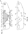
- FIG. 16 depicts a portion of an example linkage assembly 1600 that forms a linkage chain 1606 in which each set of co-mounted linkages represents an individual linkage of previously described linkage assembly 400 of FIG. 4 .
- linkage assembly 1600 can provide the same annular shape 402 and flattened shape 602 as previously described with reference to FIG. 4 and FIG. 6 , respectively, when viewed within plane of rotation 116.
- linkage assembly 1600 is viewed along an axis that is orthogonal to plane of rotation 116 (shown in FIG. 1 ), thereby providing an edge view of the linkage assembly and its various linkages.
- a material layer (not shown in FIG. 16 ) can be mounted to linkage assembly 1600 along a face of the linkage assembly shown by the edge view in FIG. 16 , such as previously described with reference to material layers 210, 480, 1316, and 1500 as examples.
- Linkage assembly 1600 includes a first set of co-mounted linkages 1610-1 rotatably coupled to a second set of co-mounted linkages 1610-2 via a hinge 1603-1 formed by a first set of pin-in-slot joints 1670-1 and a second set of pin-in-slot joints 1672-1.
- Hinge 1603-1 is an example of previously described hinge 103-1 of FIGS. 1-4 that can be used to rotatably couple two sets of co-mounted linkages to each other.
- the first set of co-mounted linkages 1610-1 includes two or more co-mounted linkages mounted in parallel with each other via a first pin 118-1.1 of the first set of pin-in-slot joints 1670-1 and a second pin 122-1.1 of the second set of pin-in-slot joints 1672-1.
- the first set of co-mounted linkages 1610-1 includes four co-mounted linkages 110-1.1, 110-1.2, 110-1.3, and 110-1.4. It will be understood that the first set of co-mounted linkages 1610-1 can include other suitable quantity of co-mounted linkages (e.g., 2, 3, 5 or more co-mounted linkages).
- Each co-mounted linkage of the first set of co-mounted linkages 1610-1 refers to an instance of previously described linkage 110-1 having linkage configuration 110, as depicted schematically in FIG. 16 . Accordingly, each co-mounted linkage of the first set of co-mounted linkages 1610-1 can have the same shape and features as previously described linkage configuration 110. Furthermore, it will be understood that the first set of co-mounted linkages 1610-1 can be used in place of linkage 110-1 in the various linkage assemblies of the preceding examples described herein.
- each co-mounted linkage of the second set of co-mounted linkages 1610-2 refers to an instance of previously described linkage 110-2 having linkage configuration 110. Accordingly, each co-mounted linkage of the second set of co-mounted linkages 1610-2 can have the same shape and features as previously described linkage configuration 110. Furthermore, it will be understood that the second set of co-mounted linkages 1610-2 can be used in place of linkage 110-2 in the various linkage assemblies of the preceding examples described herein.
- First pin 118-1.1 and second pin 122-1.1 of hinge 1603-1 can be used in place of and provide similar function as previously described pins 118-1 and 122-1 of FIG. 1 with respect to rotatably coupling two sets of co-mounted linkages to each other.
- first pin 118-1.1 and second pin 122-1.1 span each co-mounted linkage of the first set of co-mounted linkages 1610-1 and the second set of co-mounted linkages 1610-2.
- first pin 118-1.1 passes through and is retained within first curved slot 120 formed in each co-mounted linkage of the first set of co-mounted linkages 1610-1, and passes through and is retained within first circular opening 119 formed in each co-mounted linkage of the second set of co-mounted linkages 1610-2.
- Second pin 122-1/1 passes through and is retained within second curved slot 124 formed in each co-mounted linkage of the first set of co-mounted linkages 1610-1, and pass through and is retained within second circular opening 123 formed in each co-mounted linkage of the second set of co-mounted linkages 1610-2.
- the first set of co-mounted linkages 1610-1 and the second set of co-mounted linkages 1610-2 have different quantities of co-mounted linkages.
- the first set of co-mounted linkages 1610-1 includes four linkages
- the second set of co-mounted linkages 1610-2 includes three linkages.
- the first set of co-mounted linkages 1610-1 and the second set of co-mounted linkages 1610-2 are interspersed with each other.
- linkage 110-2.1 is located between linkages 110-1.1 and 110-1.2
- linkage 110-2.2 is located between linkages 110-1.2 and 110-1.3
- linkage 110-2.3 is located between linkages 110-1.3 and 110-1.4.
- each set of pin-in-slot joints that rotatably couple two sets of co-mounted linkages to each other can include spacers between linkages of the two sets. These spacers can take the form of a washer or a bushing, as examples.
- the first set of pin-in-slot joints 1670-1 includes spacers 1618-1.1, 1618.1.2, 1618-1.3, 1618.1.4, and 1618-1.5 mounted on pin 118-1.1, and located between respective linkages of the first set of co-mounted linkages 1610-1 and the second set of co-mounted linkages 1610-2.
- the second set of pin-in-slot joints 1672-1 includes spacers 1622-1.1, 1622.1.2, 1622-1.3, 1622.1.4, and 1622-1.5 mounted on pin 122-1.1, and located between respective linkages of the first set of co-mounted linkages 1610-1 and the second set of co-mounted linkages 1610-2.
- Linkage assembly 1600 further includes a third set of co-mounted linkages 1610-3 that is rotatably coupled to the second set of co-mounted linkages 1610-2 via a hinge 1603-2 formed by a first set of pin-in-slot joints 1670-2 and a second set of pin-in-slot joints 1672-2.
- Hinge 1603-2 is an example of previously described hinge 103-2 of FIG. 4 .
- the first set of pin-in-slot joints 1670-2 and the second set of pin-in-slot joints 1672-2 of hinge 1603-2 can be similarly configured as the first set of pin-in-slot joints 1670-1 and a second set of pin-in-slot joints 1672-1 of hinge 1603-1.
- first set of pin-in-slot joints 1670-2 and the second set of pin-in-slot joints 1672-2 of hinge 1603-2 each include pins upon which the linkages of the second set of co-mounted linkages 1610-2 and the third set of co-mounted linkages 1610-3 are mounted.
- pins of the first set of pin-in-slot joints 1670-2 and the second set of pin-in-slot joints 1672-2 of hinge 1603-2 span the linkages of the second set of co-mounted linkages 1610-2 and the third set of co-mounted linkages 1610-3, and spacers can be included between linkages of the second and third sets of co-mounted linkages.
- the third set of co-mounted linkages 1610-3 includes four co-mounted linkages that are interspersed with three co-mounted linkages of the second set of co-mounted linkages 1610-2. It will be understood that the third set of co-mounted linkages 1610-3 can include other suitable quantity of co-mounted linkages (e.g., 2, 3, 5 or more co-mounted linkages).
- Each co-mounted linkage of the third set of co-mounted linkages 1610-3 refers to an instance of previously described linkage 110-3 of FIG. 4 . Accordingly, each co-mounted linkage of the third set of co-mounted linkages 1610-3 can have the same shape and features as linkage configuration 110.
- Linkage assembly 1600 further includes a fourth set of co-mounted linkages 1610-4 that is rotatably coupled to the third set of co-mounted linkages 1610-3 via a hinge 1603-3 formed by a first set of pin-in-slot joints 1670-3 and a second set of pin-in-slot joints 1672-3.
- Hinge 1603-3 is an example of previously described hinge 103-3 of FIG. 4 .
- the fourth set of co-mounted linkages 1610-4 includes three co-mounted linkages that are interspersed with four co-mounted linkages of the third set of co-mounted linkages 1610-3.
- each co-mounted linkage of the fourth set of co-mounted linkages 1610-4 can include other suitable quantities of co-mounted linkages (e.g., 2, 4, 5 or more co-mounted linkages).
- each co-mounted linkage of the fourth set of co-mounted linkages 1610-4 refers to an instance of previously described linkage 110-4 of FIG. 4 .
- each co-mounted linkage of the fourth set of co-mounted linkages 1610-4 can have the same shape and features as linkage configuration 110', depicted schematically in FIG. 16 .
- Linkage assembly 1600 further includes a fifth set of co-mounted linkages 1630 in which each co-mounted linkage has the same shape and features as base linkage 430 of FIGS. 4 and 5 .
- the fifth set of co-mounted linkages 1630 includes five co-mounted linkages 430-1.1, 430-1.2, 430-1.3, 430-1.4, and 430-1.5 that are interspersed with the four co-mounted linkages of the first set of co-mounted linkages 1610-1.
- the fifth set of co-mounted linkages 1610-3 can include other suitable quantity of co-mounted linkages (e.g., 2, 3, 4, 6, or more co-mounted linkages).
- the fifth set of co-mounted linkages 1630 is rotatably coupled to the first set of co-mounted linkages 1610-1 via a hinge 1624-1 formed by a first set of pin-in-joints 1636-1 and a first set of pin-follower joints 1638-1.
- the first set of pin-in-slot joints 1636 includes a pin 440-1.1 and curved slot 442-1 formed in each instance of base linkage 430 of co-mounted linkages 1630, including co-mounted linkages 430-1.1, 430-1.2, 430-1.3, 430-1.4, and 430-1.5.
- Pin 440-1.1 passes through each curved slot 442-1 of co-mounted linkages 1630 and through each circular opening 123 of co-mounted linkages 1610-1.
- Pin 440-1.1 is retained within and can travel along curved slot 442-1 of each of the co-mounted linkages 1630 as co-mounted linkages 1610-1 are rotated relative to co-mounted linkages 1630, as previously described with reference to pin 440-1 of FIG. 5 .
- the first set of pin-follower joints 1638-1 includes a pin 444-1.1 and follower surface 446-1 formed in or by each instance of base linkage 430 of co-mounted linkages 1630, including co-mounted linkages 430-1.1, 430-1.2, 430-1.3, 430-1.4, and 430-1.5.
- Pin 444-1.1 passes through each of co-mounted linkages 1630 and through each circular opening 119 of co-mounted linkages 1610-1.
- Pin 444-1.1 can travel along follower surface 446-1 of each of the co-mounted linkages 1630 as co-mounted linkages 1610-1 are rotated relative to co-mounted linkages 1630, as previously described with reference to pin 444-1 of FIG. 5 .
- linkage assembly 1600 is formed by multiple sets of co-mounted linkages in which the quantity of co-mounted linkages of each set varies, progressing in a direction along linkage chain 1606.
- set 1630 includes five co-mounted linkages
- set 1610-1 includes four co-mounted linkages
- set 1610-2 includes three co-mounted linkages
- set 1610-3 includes four co-mounted linkages
- set 1610-4 includes three co-mounted linkages.
- the quantity of co-mounted linkages of each set decreases from set 1630 containing five instances of base linkage 430 to set 1610-1 containing four instances of linkage configuration 110, and to set 1610-2 containing three instances of linkage configuration 110.
- a greater quantity of co-mounted linkages can be used along a lower region of the drop tank and at an upper region of the drop tank in the vicinity of a mounting structure, whereas a lesser quantity of co-mounted linkages can be used along a side of the drop tank between the lower region and the upper region.
- the quantity of linkages can remain fixed along a linkage chain.
- FIG. 17 depicts a portion of an example reconfigurable structure 1700 that includes multiple instances of linkage assembly 1600 of FIG. 16 that are identified by reference numerals 1600-1 and 1600-2.
- the multiple instances of linkage assembly 1600 of reconfigurable structure 1700 are viewed along an axis that is orthogonal to plane of rotation 116 (shown in FIG. 1 ), thereby providing an edge view of the reconfigurable structure.
- a material layer (not shown in FIG. 17 ) can be mounted to the multiple instances of linkage assembly 1600 along a face of the linkage assemblies shown by the edge view in FIG. 17 , such as previously described with reference to material layers 210, 480, 1316, and 1500 as examples.
- trusses 1830, 1832, and 1834 can take the form of an intermediate structure that is disposed between a material layer and the linkages of linkage assembly 1800, such as previously described with reference to truss 1510 of FIG. 8 .
- spacing brackets 1730, 1732, and 1734 each define a keyway 1836 on either side of the set of co-mounted linkages 1610 that accommodates a keyed portion of trusses 1830, 1832, and 1834 to thereby stabilize and align the trusses. Additional features of trusses 1830, 1832, 1834 are described in further detail with reference to FIG. 19 .
- Clause 14 The reconfigurable structure of clause 12 or 13, wherein the first circle and the second circle are concentric; and wherein the first curved slot and the second curved slot define the same angular range of displacement.
- Clause 22 The linkage assembly of clause 21, wherein the first curved slot of each linkage of the first set of co-mounted linkages or the second set of co-mounted linkages forms an arc segment of a first circle, and the second curved slot of each linkage of the first set of co-mounted linkages or the second set of co-mounted linkages forms an arc segment of a second circle; and wherein the first circle and the second circle have a common radius center that is located on or within the material layer across the range of motion of the linkages of the first set of co-mounted linkages and the second set of co-mounted linkages.
- Clause 26 The linkage assembly of any one of clauses 21 to 25, wherein the first set of co-mounted linkages includes a different quantity of linkages than the second set of co-mounted linkages.
- Clause 28 The linkage assembly of any one of clauses 21 to 27, further comprising: a spacing bracket that spans each linkage of the first set of co-mounted linkages, wherein the spacing bracket includes a plurality of spacing structures in which each spacing structure projects into a respective space formed between each neighboring pair of linkages of the first set of co-mounted linkages.
- Clause 29 The linkage assembly of any one of clauses 21 to 28, further comprising: a first retaining bracket disposed along a first outer face of a first outer-most linkage of the first set of co-mounted linkages, wherein the first retaining bracket overlaps at least a portion of a first terminal end of the first pin; and a second retaining bracket disposed along a second outer face of a second outer-most linkage of the first set of co-mounted linkages that opposes the first outer face, wherein the second retaining bracket overlaps at least a portion of a second terminal end of the first pin.
- Clause 30 The linkage assembly of any one of clauses 21 to 29, further comprising: a spacing bracket that spans each linkage of the first set of co-mounted linkages; wherein the spacing bracket includes a plurality of spacing structures in which each spacing structure projects into a respective space formed between each neighboring pair of linkages of the first set of co-mounted linkages; and wherein the first retaining bracket and the second retaining bracket are mounted to the spacing bracket.
- a reconfigurable structure comprising: a plurality of linkage assemblies spaced apart from each other along a longitudinal axis, wherein each linkage assembly of the plurality of linkage assemblies includes: a first set of co-mounted linkages rotatably coupled to a second set of co-mounted linkages via a hinge formed by a first set of pin-in-slot joints and a second set of pin-in-slot joints, wherein the first set of co-mounted linkages includes two or more linkages mounted in parallel with each other via a first pin of the first set of pin-in-slot joints and a second pin of the second set of pin-in-slot joints, wherein the second set of co-mounted linkages includes two or more linkages mounted in parallel with each other via the first pin and the second pin, wherein the first pin is retained within a respective first curved slot formed in each linkage of the first set of co-mounted linkages or the second set of co-mounted linkages, wherein the second pin is retained within a respective second curved slot
- Clause 33 The reconfigurable structure of clause 32, wherein the first set of pin-in-slot joints includes a first curved slot that forms an arc segment of a first circle, and the second set of pin-in-slot joints includes a second curved slot that forms an arc segment of a second circle; and wherein the first circle and the second circle have a common radius center that is located on or within the material layer.
- Clause 37 The reconfigurable structure of clause 36, further comprising, in the first configuration, the material layer forms an annular tube shape, wherein: a first end cap mounted to a first terminal end of the annular tube shape of the material layer; a second end cap mounted to a second terminal end of the annular tube shape of the material layer; and a spine coupled to each of the plurality of linkage assemblies along the longitudinal axis and spanning the annular tube shape.
- Clause 38 The reconfigurable structure of any one of clauses 32 to 37, wherein the reconfigurable structure forms at least a portion of a fluid vessel, a conduit, an airfoil, a hydrofoil, a control surface, or a wheel.
Landscapes
- Engineering & Computer Science (AREA)
- Mechanical Engineering (AREA)
- General Engineering & Computer Science (AREA)
- Pivots And Pivotal Connections (AREA)
Applications Claiming Priority (2)
| Application Number | Priority Date | Filing Date | Title |
|---|---|---|---|
| US202363612940P | 2023-12-20 | 2023-12-20 | |
| US18/733,720 US20250382098A1 (en) | 2023-12-20 | 2024-06-04 | Linkage assembly supporting a material layer that maintains a constant length across a range of motion |
Publications (1)
| Publication Number | Publication Date |
|---|---|
| EP4579103A1 true EP4579103A1 (de) | 2025-07-02 |
Family
ID=93925511
Family Applications (1)
| Application Number | Title | Priority Date | Filing Date |
|---|---|---|---|
| EP24220898.1A Pending EP4579103A1 (de) | 2023-12-20 | 2024-12-18 | Verbindungsanordnung zur unterstützung einer materialschicht, die über einen bewegungsbereich eine konstante länge beibehält |
Country Status (2)
| Country | Link |
|---|---|
| US (1) | US20250382098A1 (de) |
| EP (1) | EP4579103A1 (de) |
Citations (4)
| Publication number | Priority date | Publication date | Assignee | Title |
|---|---|---|---|---|
| JPS55133987A (en) * | 1979-04-06 | 1980-10-18 | Ricoh Co Ltd | Inking roller loading/unloading apparatus for printing machine |
| US20080309122A1 (en) * | 2007-05-17 | 2008-12-18 | Advanced Transit Dynamics, Inc. | Rear-mounted aerodynamic structure for truck cargo bodies |
| US20090212594A1 (en) * | 2008-02-21 | 2009-08-27 | Thomas Scott Breidenbach | Aerodynamic drag reducing apparatus |
| US20180266154A1 (en) * | 2017-03-15 | 2018-09-20 | Lenovo (Beijing) Co., Ltd. | Rotary shaft |
-
2024
- 2024-06-04 US US18/733,720 patent/US20250382098A1/en active Pending
- 2024-12-18 EP EP24220898.1A patent/EP4579103A1/de active Pending
Patent Citations (4)
| Publication number | Priority date | Publication date | Assignee | Title |
|---|---|---|---|---|
| JPS55133987A (en) * | 1979-04-06 | 1980-10-18 | Ricoh Co Ltd | Inking roller loading/unloading apparatus for printing machine |
| US20080309122A1 (en) * | 2007-05-17 | 2008-12-18 | Advanced Transit Dynamics, Inc. | Rear-mounted aerodynamic structure for truck cargo bodies |
| US20090212594A1 (en) * | 2008-02-21 | 2009-08-27 | Thomas Scott Breidenbach | Aerodynamic drag reducing apparatus |
| US20180266154A1 (en) * | 2017-03-15 | 2018-09-20 | Lenovo (Beijing) Co., Ltd. | Rotary shaft |
Also Published As
| Publication number | Publication date |
|---|---|
| US20250382098A1 (en) | 2025-12-18 |
Similar Documents
| Publication | Publication Date | Title |
|---|---|---|
| EP4575265A1 (de) | Verbindungsanordnung zur unterstützung einer materialschicht, die über einen bewegungsbereich eine konstante länge beibehält | |
| US5263821A (en) | Mid-beam jointed reconfigurable bearingless main rotor assembly | |
| US7931240B2 (en) | Cellular support structures used for controlled actuation of fluid contact surfaces | |
| CA2806277C (en) | Offset stacked yoke hub for tiltrotor aircraft | |
| EP2470422B1 (de) | Adaptiver strukturkern für transformierbare panelstrukturen | |
| EP2772427A1 (de) | Vertikal integrierte Träger | |
| US8703268B2 (en) | Morphing panel structure | |
| EP2623418B1 (de) | Optimierter Kern für eine Strukturanordnung | |
| EP4579103A1 (de) | Verbindungsanordnung zur unterstützung einer materialschicht, die über einen bewegungsbereich eine konstante länge beibehält | |
| CN112977789A (zh) | 机身的受压弦杆 | |
| Jeon et al. | Scaling and optimization of a modular origami solar array | |
| US11473616B2 (en) | Flexure device | |
| US6053454A (en) | Modular spacecraft payload support structure | |
| KR20170113329A (ko) | 동체 및 복합 테일 붐을 갖는 헬리콥터 | |
| US12343869B2 (en) | Reconfigurable hybrid kinematics machine | |
| EP3345830A1 (de) | Wippendes rotornabensystem | |
| US8757544B2 (en) | Aircraft control surface drive mechanism | |
| ES2988843T3 (es) | Conjunto de larguerillo de material compuesto y procedimiento para formar un conjunto de larguerillo de material compuesto | |
| CN110202547B (zh) | 六自由度并联机构 | |
| US20260009256A1 (en) | Tower sheet assembly, tower section, and tower transportation and assembly method | |
| CN218564173U (zh) | 气浮轴承及设备 | |
| WO2017000528A1 (zh) | 一种具有多个驱动装置的驱动装置组合体及其应用 | |
| EP3281860B1 (de) | Flugzeugkabine mit sekundärer flugzeugkabinenstruktur, die mit drehgelenken angebracht ist, und verfahren zur montage einer sekundären flugzeugkabinenstruktur in einer flugzeugkabine | |
| CN116696654A (zh) | 一种分段式风力发电叶片及其运输方法 | |
| US10518905B2 (en) | System and method for rotorcraft blade storage |
Legal Events
| Date | Code | Title | Description |
|---|---|---|---|
| PUAI | Public reference made under article 153(3) epc to a published international application that has entered the european phase |
Free format text: ORIGINAL CODE: 0009012 |
|
| STAA | Information on the status of an ep patent application or granted ep patent |
Free format text: STATUS: THE APPLICATION HAS BEEN PUBLISHED |
|
| AK | Designated contracting states |
Kind code of ref document: A1 Designated state(s): AL AT BE BG CH CY CZ DE DK EE ES FI FR GB GR HR HU IE IS IT LI LT LU LV MC ME MK MT NL NO PL PT RO RS SE SI SK SM TR |
|
| STAA | Information on the status of an ep patent application or granted ep patent |
Free format text: STATUS: REQUEST FOR EXAMINATION WAS MADE |
|
| 17P | Request for examination filed |
Effective date: 20251203 |