EP4579104A1 - Dispositif d'entraînement de véhicule - Google Patents
Dispositif d'entraînement de véhicule Download PDFInfo
- Publication number
- EP4579104A1 EP4579104A1 EP23897832.4A EP23897832A EP4579104A1 EP 4579104 A1 EP4579104 A1 EP 4579104A1 EP 23897832 A EP23897832 A EP 23897832A EP 4579104 A1 EP4579104 A1 EP 4579104A1
- Authority
- EP
- European Patent Office
- Prior art keywords
- case
- axial direction
- housing chamber
- breather
- electrical machine
- Prior art date
- Legal status (The legal status is an assumption and is not a legal conclusion. Google has not performed a legal analysis and makes no representation as to the accuracy of the status listed.)
- Pending
Links
Images


Classifications
-
- H—ELECTRICITY
- H02—GENERATION; CONVERSION OR DISTRIBUTION OF ELECTRIC POWER
- H02K—DYNAMO-ELECTRIC MACHINES
- H02K5/00—Casings; Enclosures; Supports
- H02K5/04—Casings or enclosures characterised by the shape, form or construction thereof
- H02K5/10—Casings or enclosures characterised by the shape, form or construction thereof with arrangements for protection from ingress, e.g. water or fingers
-
- F—MECHANICAL ENGINEERING; LIGHTING; HEATING; WEAPONS; BLASTING
- F16—ENGINEERING ELEMENTS AND UNITS; GENERAL MEASURES FOR PRODUCING AND MAINTAINING EFFECTIVE FUNCTIONING OF MACHINES OR INSTALLATIONS; THERMAL INSULATION IN GENERAL
- F16H—GEARING
- F16H57/00—General details of gearing
- F16H57/02—Gearboxes; Mounting gearing therein
- F16H57/027—Gearboxes; Mounting gearing therein characterised by means for venting gearboxes, e.g. air breathers
-
- F—MECHANICAL ENGINEERING; LIGHTING; HEATING; WEAPONS; BLASTING
- F16—ENGINEERING ELEMENTS AND UNITS; GENERAL MEASURES FOR PRODUCING AND MAINTAINING EFFECTIVE FUNCTIONING OF MACHINES OR INSTALLATIONS; THERMAL INSULATION IN GENERAL
- F16H—GEARING
- F16H57/00—General details of gearing
- F16H57/04—Features relating to lubrication or cooling or heating
-
- F—MECHANICAL ENGINEERING; LIGHTING; HEATING; WEAPONS; BLASTING
- F16—ENGINEERING ELEMENTS AND UNITS; GENERAL MEASURES FOR PRODUCING AND MAINTAINING EFFECTIVE FUNCTIONING OF MACHINES OR INSTALLATIONS; THERMAL INSULATION IN GENERAL
- F16H—GEARING
- F16H57/00—General details of gearing
- F16H57/02—Gearboxes; Mounting gearing therein
- F16H2057/02034—Gearboxes combined or connected with electric machines
-
- H—ELECTRICITY
- H02—GENERATION; CONVERSION OR DISTRIBUTION OF ELECTRIC POWER
- H02K—DYNAMO-ELECTRIC MACHINES
- H02K2205/00—Specific aspects not provided for in the other groups of this subclass relating to casings, enclosures, supports
- H02K2205/09—Machines characterised by drain passages or by venting, breathing or pressure compensating means
-
- H—ELECTRICITY
- H02—GENERATION; CONVERSION OR DISTRIBUTION OF ELECTRIC POWER
- H02K—DYNAMO-ELECTRIC MACHINES
- H02K7/00—Arrangements for handling mechanical energy structurally associated with dynamo-electric machines, e.g. structural association with mechanical driving motors or auxiliary dynamo-electric machines
- H02K7/10—Structural association with clutches, brakes, gears, pulleys or mechanical starters
- H02K7/116—Structural association with clutches, brakes, gears, pulleys or mechanical starters with gears
Definitions
- the present disclosure relates to a vehicular drive device.
- a technique is known in which, in a vehicular drive device, a breather chamber communicated with an outside of a case is partitioned to a motor housing chamber of the case.
- a breather recess (breather chamber) is closed by a flat breather plate, and in a case where capacity of the breather chamber is increased, the case may be increased in size along with an increase in size of the breather recess.
- the present disclosure intends to efficiently secure a necessary capacity of a breather chamber while preventing an increase in size of a case.
- a vehicular drive device includes
- a Y direction correspond to an up-down direction in a state where a vehicular drive device 100 is in use, that is, an up-down direction with respect to an orientation in which the vehicular drive device 100 in use is disposed.
- a Y1 side and a Y2 side correspond to an upper side and a lower side along the Y direction.
- the up-down direction is not necessarily parallel to a vertical direction, and it is only required that a vertical direction component is predominant.
- orientations of respective members in the following description represent orientations in a state where the respective members are fitted to the vehicular drive device 100.
- an A direction corresponds to an axial direction
- an A1 side and an A2 side along the A direction are defined in FIG. 2 and the like.
- an X direction is a direction orthogonal to both the A direction and the Y direction, and an X1 side and an X2 side along the X direction are defined in FIG. 3 and the like.
- “communication” refers to a state in which two spatial elements in fluid communication with each other. That is, “communication” refers to a state in which fluid can move back and forth between the two spatial elements. In this case, the two spatial elements may communicate directly or indirectly (that is, via another spatial element).
- the "rotating electrical machine” is used as a concept including any of a motor (electric motor), a generator (generator), and a motor-generator that functions as both the motor and the generator as necessary.
- "to overlap as viewed in a specific direction” means that, in a case where a virtual straight line parallel to the direction of a line of sight is moved in each direction orthogonal to the virtual straight line, a region where the virtual straight line intersects both of the two members exists in at least a part.
- “disposition regions in a specific direction overlap” means that at least a part of a disposition region in a specific direction of one member is included in a disposition region in a specific direction of another member.
- FIG. 1 is a schematic top view showing a state of the vehicular drive device 100 mounted on a vehicle VC.
- FIG. 2 is a cross-sectional view of the vehicular drive device 100.
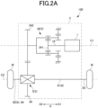
- FIG. 2A is a skeleton diagram showing the vehicular drive device 100.
- the vehicular drive device 100 includes a rotating electrical machine 1, a pair of output members 6 drivingly coupled to a pair of wheels W (refer to FIG. 1 ), and a transmission mechanism 3 that transmits drive force between the rotating electrical machine 1 and the pair of output members 6.
- the vehicular drive device 100 further includes a case 2 that houses the rotating electrical machine 1.
- the case 2 also houses the pair of output members 6 and the transmission mechanism 3. Note that, in a modification, the case 2 may house only one (a first output member 61, for example) of the pair of output members 6.
- a drive source may be only an engine (internal combustion engine).
- a first output member 61 which is one of the pair of output members 6, is drivingly coupled to a first wheel W1, which is one of the pair of wheels W.
- a second output member 62 which is another one of the pair of output members 6, is drivingly coupled to a second wheel W2, which is another one of the pair of wheels W.
- the vehicle VC on which the vehicular drive device 100 is mounted includes a first drive shaft 63 that rotates integrally with the first wheel W1 and a second drive shaft 64 that rotates integrally with the second wheel W2.
- the first drive shaft 63 is coupled to the first wheel W1 via, for example, a constant-velocity joint
- the second drive shaft 64 is coupled to the second wheel W2 via, for example, a constant-velocity joint.
- the first output member 61 is coupled to the first drive shaft 63 so as to rotate integrally with the first drive shaft 63
- the second output member 62 is coupled to the second drive shaft 64 so as to rotate integrally with the second drive shaft 64.
- the first output member 61 may be in a form of an intermediate shaft.
- the first output member 61 is rotatably supported with respect to the case 2 via a bearing BR1 on an axial direction second side A2, and is rotatably supported with respect to the case 2 via a bearing BR2 on an axial direction first side A1.
- the bearings BR1 and BR2 are in a form of ball bearing.
- the bearings BR1 and BR2 may be in another form.
- the vehicular drive device 100 transmits output torque of the rotating electrical machine 1 to the pair of wheels W via the pair of output members 6 to cause the vehicle VC equipped with the vehicular drive device 100 to travel. That is, the rotating electrical machine 1 is a drive force of the pair of wheels W.
- the pair of wheels W is a pair of left and right wheels (for example, a pair of left and right front wheels or a pair of left and right rear wheels) in the vehicle VC.
- the rotating electrical machine 1 may be, for example, an alternating-current rotating electrical machine driven by three-phase alternating current power.
- the rotating electrical machine 1 and the pair of output members 6 are disposed separately on two axes (specifically, a first axis C1 and a second axis C2) parallel to each other.
- the rotating electrical machine 1 is disposed on the first axis C1
- the pair of output members 6 is disposed on the second axis C2 different from the first axis C1.
- the first axis C1 and the second axis C2 are axes (virtual axes) arranged parallel to each other.
- the transmission mechanism 3 includes an output gear (ring gear) 30 drivingly coupled to at least one of the pair of output members 6, coaxially with the pair of output members 6 (that is, on the second axis C2).
- the rotating electrical machine 1 is, for example, inner rotor type.
- a rotor 14 that is rotatable about the first axis C1 is disposed radially inner side of a stator 11 (refer to FIG. 2 ).
- the rotor shaft 15 of the rotor 14 is rotatably supported with respect to the case 2 via a bearing BR3 on an axial direction second side A2, and is rotatably supported with respect to the case 2 via a bearing BR4 on an axial direction first side A1.
- the bearings BR3 and BR4 are in a form of ball bearing.
- the bearings BR1 and BR2 may be in another form. Note that, in the example shown in FIG.
- the rotor shaft 15 has the shaft center oil passage 15a and an ejection vent 15b in a radial direction, and, during rotation, can eject oil in a shaft center oil passage 15a from each ejection vent 15b in the radial direction toward a coil end 13 by centrifugal force.
- the transmission mechanism 3 includes a deceleration mechanism 34 in a power transmission path between the rotating electrical machine 1 and an output gear 30.
- the deceleration mechanism 34 is arbitrary, and may include a deceleration mechanism using a counter gear, a deceleration mechanism using a planetary gear, and the like.
- the deceleration mechanism 34 includes a planetary gear mechanism, and the deceleration mechanism 34 is disposed coaxially with the rotating electrical machine 1.
- An output gear (carrier) 342 of the deceleration mechanism 34 meshes with the output gear 30 of a differential gear mechanism 5 in a radial direction.
- Such a vehicular drive device 100 can have a compact configuration including two axes (the first axis C1 and the second axis C2). Note that, in a modification, the vehicular drive device 100 may have three or more axes.
- the deceleration mechanism 34 is disposed coaxially with the rotating electrical machine 1 (that is, on the first axis C1) in such a manner as to be drivingly coupled to the rotating electrical machine 1.
- the rotor 14 of the rotating electrical machine 1 rotates integrally with an input member 16 together with a sun gear 341 of the deceleration mechanism 34.
- the transmission mechanism 3 further includes the differential gear mechanism 5.
- the differential gear mechanism 5 distributes the drive force transmitted from a rotating electrical machine 1 side to the pair of output members 6.
- the differential gear mechanism 5 distributes rotation of the output gear 30 to a first side gear 51 and a second side gear 52.
- the differential gear mechanism 5 may be disposed coaxially with the pair of output members 6 (that is, on the second axis C2).
- the differential gear mechanism 5 may be a bevel-gear type differential gear mechanism, and the output gear 30 may be coupled to a differential case part 50 so as to rotate integrally with the differential case part 50 included in the differential gear mechanism 5.
- FIG. 3 is a top view schematically showing the vehicular drive device 100 according to the present embodiment.
- an inverter cover member 203 on an upper portion of an inverter case part 24 is not shown so that elements disposed inside the inverter case part 24 can be seen.
- the case 2 includes a motor case part 21, a transmission mechanism case part 22, an output shaft case part 23, and an inverter case part 24 in an integrated form.
- the "integrated form” includes an integrated form using a fastening member such as a bolt and an integrated form utilizing integral molding (for example, casting or pouring utilizing aluminizing or the like).
- the motor case part 21 forms the motor housing chamber S1 that houses the rotating electrical machine 1
- the transmission mechanism case part 22 forms a transmission mechanism housing chamber S2 that houses the transmission mechanism 3
- the output shaft case part 23 forms the output shaft housing chamber S3 that houses the first output member 61
- the inverter case part 24 forms an inverter housing chamber S4 that houses the inverter device 70.
- the motor case part 21 forming the motor housing chamber S1 means that a wall part that bounds the motor housing chamber S1 forms the motor case part 21.
- the motor case part 21 has a cylindrical shape corresponding to an outer shape of the rotating electrical machine 1. However, an entire cylindrical outer peripheral part of the motor case part 21 is not necessarily closed.
- the motor housing chamber S1 and the output shaft housing chamber S3 may communicate with each other, and in this case, a wall part (partition wall part) may not be formed on a side of the motor case part 21, the side facing the output shaft housing chamber S3.
- the transmission mechanism case part 22 is provided on the axial direction second side A2 with respect to the motor case part 21 and the output shaft case part 23.
- the output shaft case part 23 is provided on the X2 side in the X direction with respect to the motor case part 21.
- the inverter case part 24 is provided on the upper side of the transmission mechanism case part 22 and the output shaft case part 23. Details of the inverter case part 24 will be described later.
- the output shaft case part 23 is provided. Therefore, the first output member 61 can be effectively protected from an external environment (for example, a splashing stone or the like) as compared with a case where the first output member 61 is provided outside the case 2. Furthermore, clearance to be secured between the first output member 61 and peripheral components can be reduced. However, in a modification, the first output member 61 may be provided outside the case 2.
- the case 2 is formed by joining a case member 200, the motor cover member 201, a differential cover member 202, and an inverter cover member 203.
- a joining method may be fastening with bolts or the like.
- the inverter case part 24 is disposed so as to overlap the first axis C1 and the second axis C2 as viewed from top (viewed in a second direction Y, hereinafter the same).
- the inverter housing chamber S4 extends on both sides of the A direction with respect to the center in the A direction in a manner of extending across the center in the A direction.
- the inverter housing chamber S4 extends only on the axial direction second side A2 of the center in the A direction.
- the first housing part S41, the second housing part S42, and the third housing part S43 are disposed above a plane (not shown) including the first axis C1 that is an axial center of a rotary shaft of the rotating electrical machine 1 and the second axis C2 that is an axial center of the output members 6.
- a plane (not shown) including the first axis C1 and the second axis C2 is a plane close to a horizontal plane.
- first housing part S41, the second housing part S42, and the third housing part S43 do not need to be specific, and for example, a portion of the power module PM in the axial direction first side A1 may be disposed in the second housing part S42, and a portion of the power module PM in the first direction first side X1 may be disposed in the first housing part S41.
- FIG. 3A is a side view from the axial direction first side A1, schematically showing the vehicular drive device according to the present embodiment.
- the motor cover member 201 is not shown so that a state of an inside of the motor housing chamber S1 can be seen.
- an inverter device 70 inside an inverter case part 24 is schematically shown by a dotted line.
- FIG. 4 is a perspective view of the channel forming member 90.
- the water-cooling structure of the rotating electrical machine 1 is a structure for cooling the rotating electrical machine 1 with cooling water.
- the cooling water may be, for example, water containing long life coolant: LLC, and may be circulated by a water pump (not shown).
- a heat radiation unit such as a radiator (not shown) may be provided in the circulation path of the cooling water.
- the cooling water may be utilized not only for cooling the rotating electrical machine 1 but also for cooling another component, for example, the inverter device 70 or the like electrically connected to the rotating electrical machine 1.
- the water-cooling structure of the rotating electrical machine 1 includes a refrigerant supply unit 40, a refrigerant discharge unit 42, and a channel forming member 90.
- the refrigerant supply unit 40 communicates with, for example, a discharge side of the water pump (not shown), and supplies the cooling water to the refrigerant channel 300 formed by the channel forming member 90.
- the refrigerant discharge unit 42 communicates with, for example, a suction side of the water pump (not shown), and supplies (discharges) the cooling water from the refrigerant channel 300 formed by the channel forming member 90 to the water pump (not shown).
- the refrigerant supply unit 40 and the refrigerant discharge unit 42 may be provided on upper and lower sides with the first output member 61 interposed therebetween. In this case, the refrigerant supply unit 40 and the refrigerant discharge unit 42 can be established by effectively utilizing space around the first output member 61.
- the channel forming member 90 has a cylindrical shape having an inner peripheral surface radially facing an outer peripheral surface of the rotating electrical machine 1.
- the channel forming member 90 forms the refrigerant channel 300 around the rotating electrical machine 1.
- the refrigerant channel 300 has a plurality of channel parts SC1 to SC4 in a circumferential direction, but the refrigerant channel 300 can be arbitrarily configured.
- the channel forming member 90 may be formed of a material having good thermal conductivity, such as aluminum, for example
- the channel forming member 90 is fitted to a stator core 12 of the stator 11 by shrink-fitting, for example.
- the channel forming member 90 may be integrally formed with the stator core 12 by casting or the like.
- the channel forming member 90 is in a form of the inner case fastened to the case 2.
- an axially one end side of the channel forming member 90 may have a plurality of fastening parts 500 as shown in FIG. 3A .
- the plurality of fastening parts 500 are fastened to the case 2 by bolts (not shown) (refer to bolt holes BT4).
- the channel forming member 90 may be formed as a part of the case 2.
- the channel forming member 90 is inserted into a space having a columnar shape in the case 2. At this time, an outer peripheral surface of the channel forming member 90 radially faces an inner peripheral surface (inner peripheral surface that bounds the plurality of fastening parts 500) of the case 2.
- an inner peripheral surface of the case 2 surrounding the channel forming member 90 in this manner is also referred to as a "channel forming surface 209 of the case 2" (refer to FIG. 5 ).
- an inner diameter of the channel forming surface 209 of the case 2 may be a constant value larger by a base thickness of the channel forming member 90 than a base outer diameter of the stator core 12.
- the transmission mechanism housing chamber S2 and the output shaft housing chamber S3 overlap the second axis C2 as viewed from top and are adjacent to each other in the axial direction. Furthermore, because the transmission mechanism housing chamber S2 extends in the X direction in such a manner as to house the deceleration mechanism 34 and the differential gear mechanism 5, the transmission mechanism housing chamber S2 and the output shaft housing chamber S3 extend in an L shape as viewed from top.
- a part housing the deceleration mechanism 34 is also referred to as a "deceleration mechanism housing chamber S21”
- a part housing the differential gear mechanism 5 is also referred to as a "differential gear housing chamber S22".
- the output shaft case part 23 extends around the second axis C2 along an extending direction (that is, the axial direction) of the first output member 61.
- the output shaft case part 23 may be in a form of a peripheral wall part that forms a space (the output shaft housing chamber S3) around the first output member 61. Note that, in this case, the output shaft case part 23 may extend radially outer side (X direction X2 side) of the rotating electrical machine 1, and may also form a part of the motor case part 21.
- a lubrication system is adopted in which various objects to be lubricated are scraped up by rotation of the output gear 30 (so-called a differential ring) of the differential gear mechanism 5.
- the return channel 290 is opened at a lower portion (below the second axis C2) of the differential gear housing chamber S22 of the transmission mechanism housing chamber S2.
- the end portion on the axial direction second side A2 of the return channel 290 (opening on a differential gear housing chamber S22 side) preferably overlaps the output gear 30 as viewed in the axial direction.
- the oil returned to the transmission mechanism housing chamber S2 in this manner is returned to the differential gear housing chamber S22 from the discharge port 922 below the second axis C2 in the catch tank 920.
- the rotation of the output gear 30 of the differential gear mechanism 5 can scrape up the oil again.
- the third opening 156 is disposed near a central portion of the case 2 as viewed in the up-down direction. Specifically, the third opening 156 is disposed between the first axis C1 and the second axis C2 in the first direction X (an example of a direction perpendicular to a first axis) and between a center position of the rotating electrical machine 1 and a center position of the deceleration mechanism 34 in the axial direction A (an example of a direction parallel to the first axis). Note that the center position of the rotating electrical machine 1 in the axial direction A may correspond to, for example, a center position of the stator core 12 in the axial direction.
- the breather 150 According to such a disposition of the breather 150, it is possible to easily establish the breather 150 by utilizing a dead space which easily formed, between the rotating electrical machine 1 and the deceleration mechanism 34 and between the first axis C1 and the second axis C2, in the axial direction A.
- the third opening 156 of the breather 150 can be disposed near the central portion of the case 2 as viewed in the up-down direction, while reducing a size of the vehicular drive device 100 in the up-down direction.
- FIG. 8 is a schematic cross-sectional view of a vehicular drive device 100A, taken along a vertical plane passing through a breather 150A according to the present second embodiment.
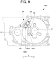
- FIG. 9 is a side view from the axial direction first side A1, schematically showing a partition wall 26 in the vehicular drive device 100A according to the present second embodiment.
- a part of the configuration (the rotating electrical machine 1 and the like) in the motor housing chamber S1 is not shown for ease of viewing.
- a part (lid part 169) of an insulating member 160 described later is not shown for ease of viewing.
- the breather 150A is different from the breather 150 according to the above-described first embodiment in a configuration on a motor housing chamber S1 side.
- the breather 150A has an opening 155A on the motor housing chamber S1 side formed by a case 2A, instead of the first opening 153 of the breather 150 according to the first embodiment described above. Unlike the breather 150 according to the first embodiment described above, the breather 150A is opened to the motor housing chamber S1 via the insulating member 160 that is a member different from the case 2A described later.
- the insulating member 160 is formed by an insulating material (for example, a resin material) having an electrical insulating property, and forms an insulating part of breather 150A. That is, the breather 150A includes an insulating part formed by the insulating member 160 in addition to a conductor portion formed by the case 2A.
- an insulating material for example, a resin material
- the rotation angle sensor 88 is in a form of, for example, a resolver, but may be in another form.
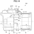
- FIG. 14 is a schematic cross-sectional view of a vehicular drive device 100A according to the comparative example, taken along a vertical plane passing through a breather 150'.
- a breather 150' according to the comparative example is different from the breather 150A according to the present second embodiment in that the insulating member 160 is replaced with a lid member 28' made of metal.
- the lid member 28' is formed of, for example, a material (for example, aluminum) similar to the case 2A.
- the lid member 28' is in a form of a flat plate and covers the opening 155A on the axial direction first side A1 in the first passage 151. Note that the lid member 28' may form the drain hole 1641' and the vent hole 1631'.
- the first passage 151 faces the coil end 13-1 as viewed in the axial direction A. Therefore, if the first passage 151 is extended to the axial direction first side A1, an electrical insulation distance between the coil end 13-1 and an end portion on the axial direction first side A1 in the case 2A (specifically, an outer peripheral edge portion around the first passage 151) is shortened. Therefore, due to necessity (restriction) of securing a necessary electrical insulation distance between the coil end 13-1 and the end portion on the axial direction first side A1 of the case 2A, it is difficult to increase the capacity of the breather chamber by extending the first passage 151 to the axial direction first side A1.
- the lid member 28' is a conductor axially facing the coil end 13-1. Therefore, the lid member 28' is disposed away from the coil end 13-1 by a necessary electrical insulation distance L14 (refer to FIG. 14 ) or more.
- the insulating member 160 described above is provided so as to cover a portion 29 (a portion of the partition wall 26) around the first passage 151 in the case 2A.
- the insulating member 160 is positioned between the portion 29 around the first passage 151 in the case 2A and the coil end 13-1.
- the above-described insulating member 160 can be brought close to the coil end 13-1 while facing the coil end 13-1 in the axial direction.
- the second opening 154 may be omitted. That is, the breather 150A may not be opened to the transmission mechanism housing chamber S2.
- the third opening 156 similar to the third opening 156 in the first embodiment described above is provided.
- an opening (vent opening opened to the atmosphere) corresponding to the third opening 156 may be provided at a position different from a position of the third opening 156 in the first embodiment described above.
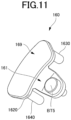
- the ventilation hollow projection part 1630 and the drain hollow projection part 1640 are provided in the second embodiment.
- either one or both of the ventilation hollow projection part 1630 and the drain hollow projection part 1640 may be omitted in the present second embodiment.
- a vent hole may be provided on an upper side of the lid part 169.
- the vent hole 1631 of the breather 150A is opened to the motor housing chamber S1.
- the vent hole 1631 may be provided to be opened to the transmission mechanism housing chamber S2.
- the ventilation hollow projection part 1630 may be omitted, or a similar ventilation hollow projection part, which is different only in not having the vent hole 1631, may be provided. Even in the latter case, necessary capacity of the breather chamber of the breather 150A can still be efficiently secured.
- the drain hole 1641 of the breather 150A is opened to the motor housing chamber S1.
- the drain hole 1641 may be provided to be opened to the transmission mechanism housing chamber S2.
- the drain hollow projection part 1640 may be omitted, or a similar drain hollow projection part, which is different only in not having the drain hole 1641, may be provided. Even in the latter case, necessary capacity of the breather chamber of the breather 150A can still be efficiently secured.
- the rotating electrical machine 1 and the transmission mechanism 3 are provided, but either one may be omitted.
- an insulating member corresponding to the insulating member 160 may be provided on a second opening 154 side.
- the invention according to the following supplementary note intends to eliminate or reduce an increase in size of a vehicular drive device caused by a breather.
- a vehicular drive device including
Landscapes
- Engineering & Computer Science (AREA)
- General Engineering & Computer Science (AREA)
- Mechanical Engineering (AREA)
- Power Engineering (AREA)
- Hybrid Electric Vehicles (AREA)
Applications Claiming Priority (3)
| Application Number | Priority Date | Filing Date | Title |
|---|---|---|---|
| JP2022191022 | 2022-11-30 | ||
| JP2023194700A JP2024079610A (ja) | 2022-11-30 | 2023-11-15 | 車両用駆動装置 |
| PCT/JP2023/042747 WO2024117186A1 (fr) | 2022-11-30 | 2023-11-29 | Dispositif d'entraînement de véhicule |
Publications (2)
| Publication Number | Publication Date |
|---|---|
| EP4579104A1 true EP4579104A1 (fr) | 2025-07-02 |
| EP4579104A4 EP4579104A4 (fr) | 2025-12-17 |
Family
ID=91323868
Family Applications (1)
| Application Number | Title | Priority Date | Filing Date |
|---|---|---|---|
| EP23897832.4A Pending EP4579104A4 (fr) | 2022-11-30 | 2023-11-29 | Dispositif d'entraînement de véhicule |
Country Status (3)
| Country | Link |
|---|---|
| EP (1) | EP4579104A4 (fr) |
| CN (1) | CN119948278A (fr) |
| WO (1) | WO2024117186A1 (fr) |
Family Cites Families (8)
| Publication number | Priority date | Publication date | Assignee | Title |
|---|---|---|---|---|
| JPS5335374U (fr) * | 1976-09-02 | 1978-03-28 | ||
| JP2003161363A (ja) * | 2001-11-27 | 2003-06-06 | Honda Motor Co Ltd | 電気自動車用パワートレンのブリーザ装置 |
| JP2007127139A (ja) | 2005-10-31 | 2007-05-24 | Aisin Aw Co Ltd | ブリーザ装置 |
| JP5821435B2 (ja) * | 2011-09-06 | 2015-11-24 | スズキ株式会社 | 変速機のエアブリーザ構造 |
| JP6248487B2 (ja) * | 2013-09-12 | 2017-12-20 | 株式会社ジェイテクト | 電動ポンプ装置 |
| JP2017155921A (ja) * | 2016-03-04 | 2017-09-07 | トヨタ自動車株式会社 | エアブリーザ装置 |
| JP7070793B2 (ja) * | 2019-03-28 | 2022-05-18 | 株式会社アイシン | 回転電機 |
| JP2021170906A (ja) | 2020-04-17 | 2021-10-28 | トヨタ自動車株式会社 | 車両用駆動ユニット |
-
2023
- 2023-11-29 EP EP23897832.4A patent/EP4579104A4/fr active Pending
- 2023-11-29 CN CN202380068927.6A patent/CN119948278A/zh active Pending
- 2023-11-29 WO PCT/JP2023/042747 patent/WO2024117186A1/fr not_active Ceased
Also Published As
| Publication number | Publication date |
|---|---|
| EP4579104A4 (fr) | 2025-12-17 |
| CN119948278A (zh) | 2025-05-06 |
| WO2024117186A1 (fr) | 2024-06-06 |
Similar Documents
| Publication | Publication Date | Title |
|---|---|---|
| JP5256117B2 (ja) | モータユニット | |
| JP7723604B2 (ja) | 駆動装置 | |
| CN113193679B (zh) | 马达单元 | |
| CN114930695B (zh) | 马达单元 | |
| CN113498573A (zh) | 马达单元 | |
| EP4089891A1 (fr) | Dispositif d'entraînement de véhicule | |
| CN112770926A (zh) | 驱动装置 | |
| CN112533783A (zh) | 马达单元 | |
| WO2023095753A1 (fr) | Dispositif d'entraînement pour véhicule | |
| WO2023095752A1 (fr) | Dispositif d'entraînement pour véhicule | |
| EP4579104A1 (fr) | Dispositif d'entraînement de véhicule | |
| CN118317882A (zh) | 车用驱动装置 | |
| JP7647181B2 (ja) | 回転電機、および駆動装置 | |
| CN119159975A (zh) | 动力总成及车辆 | |
| EP4575271A1 (fr) | Dispositif d'entraînement de véhicule | |
| US20260126108A1 (en) | Vehicular drive device | |
| KR20250057636A (ko) | 구동 장치 | |
| EP4575270A1 (fr) | Dispositif d'entraînement de véhicule | |
| JP7598103B2 (ja) | 車両用駆動装置 | |
| JP2024079610A (ja) | 車両用駆動装置 | |
| JP7468313B2 (ja) | 駆動装置 | |
| US20260128639A1 (en) | Vehicular drive device | |
| EP4678946A1 (fr) | Dispositif d'entraînement de véhicule | |
| EP4576513A1 (fr) | Dispositif d'entraînement de véhicule | |
| US20260112941A1 (en) | Vehicular drive device |
Legal Events
| Date | Code | Title | Description |
|---|---|---|---|
| STAA | Information on the status of an ep patent application or granted ep patent |
Free format text: STATUS: THE INTERNATIONAL PUBLICATION HAS BEEN MADE |
|
| PUAI | Public reference made under article 153(3) epc to a published international application that has entered the european phase |
Free format text: ORIGINAL CODE: 0009012 |
|
| STAA | Information on the status of an ep patent application or granted ep patent |
Free format text: STATUS: REQUEST FOR EXAMINATION WAS MADE |
|
| 17P | Request for examination filed |
Effective date: 20250327 |
|
| AK | Designated contracting states |
Kind code of ref document: A1 Designated state(s): AL AT BE BG CH CY CZ DE DK EE ES FI FR GB GR HR HU IE IS IT LI LT LU LV MC ME MK MT NL NO PL PT RO RS SE SI SK SM TR |
|
| A4 | Supplementary search report drawn up and despatched |
Effective date: 20251113 |
|
| RIC1 | Information provided on ipc code assigned before grant |
Ipc: F16H 57/027 20120101AFI20251107BHEP Ipc: H02K 5/10 20060101ALI20251107BHEP Ipc: H02K 7/116 20060101ALI20251107BHEP |
|
| DAV | Request for validation of the european patent (deleted) | ||
| DAX | Request for extension of the european patent (deleted) |