EP4579128A2 - Système et procédé de régulation de l'humidité et de la pression dans un luminaire - Google Patents
Système et procédé de régulation de l'humidité et de la pression dans un luminaire Download PDFInfo
- Publication number
- EP4579128A2 EP4579128A2 EP25177139.0A EP25177139A EP4579128A2 EP 4579128 A2 EP4579128 A2 EP 4579128A2 EP 25177139 A EP25177139 A EP 25177139A EP 4579128 A2 EP4579128 A2 EP 4579128A2
- Authority
- EP
- European Patent Office
- Prior art keywords
- enclosure
- air
- luminaire
- sealed
- opening
- Prior art date
- Legal status (The legal status is an assumption and is not a legal conclusion. Google has not performed a legal analysis and makes no representation as to the accuracy of the status listed.)
- Pending
Links
Images




Classifications
-
- F—MECHANICAL ENGINEERING; LIGHTING; HEATING; WEAPONS; BLASTING
- F21—LIGHTING
- F21V—FUNCTIONAL FEATURES OR DETAILS OF LIGHTING DEVICES OR SYSTEMS THEREOF; STRUCTURAL COMBINATIONS OF LIGHTING DEVICES WITH OTHER ARTICLES, NOT OTHERWISE PROVIDED FOR
- F21V14/00—Controlling the distribution of the light emitted by adjustment of elements
- F21V14/006—Controlling the distribution of the light emitted by adjustment of elements by means of optical elements, e.g. films, filters or screens, being rolled up around a roller
-
- B—PERFORMING OPERATIONS; TRANSPORTING
- B01—PHYSICAL OR CHEMICAL PROCESSES OR APPARATUS IN GENERAL
- B01D—SEPARATION
- B01D53/00—Separation of gases or vapours; Recovering vapours of volatile solvents from gases; Chemical or biological purification of waste gases, e.g. engine exhaust gases, smoke, fumes, flue gases, aerosols
- B01D53/26—Drying gases or vapours
-
- F—MECHANICAL ENGINEERING; LIGHTING; HEATING; WEAPONS; BLASTING
- F21—LIGHTING
- F21V—FUNCTIONAL FEATURES OR DETAILS OF LIGHTING DEVICES OR SYSTEMS THEREOF; STRUCTURAL COMBINATIONS OF LIGHTING DEVICES WITH OTHER ARTICLES, NOT OTHERWISE PROVIDED FOR
- F21V21/00—Supporting, suspending, or attaching arrangements for lighting devices; Hand grips
- F21V21/14—Adjustable mountings
- F21V21/15—Adjustable mountings specially adapted for power operation, e.g. by remote control
-
- F—MECHANICAL ENGINEERING; LIGHTING; HEATING; WEAPONS; BLASTING
- F21—LIGHTING
- F21V—FUNCTIONAL FEATURES OR DETAILS OF LIGHTING DEVICES OR SYSTEMS THEREOF; STRUCTURAL COMBINATIONS OF LIGHTING DEVICES WITH OTHER ARTICLES, NOT OTHERWISE PROVIDED FOR
- F21V21/00—Supporting, suspending, or attaching arrangements for lighting devices; Hand grips
- F21V21/14—Adjustable mountings
- F21V21/30—Pivoted housings or frames
-
- F—MECHANICAL ENGINEERING; LIGHTING; HEATING; WEAPONS; BLASTING
- F21—LIGHTING
- F21V—FUNCTIONAL FEATURES OR DETAILS OF LIGHTING DEVICES OR SYSTEMS THEREOF; STRUCTURAL COMBINATIONS OF LIGHTING DEVICES WITH OTHER ARTICLES, NOT OTHERWISE PROVIDED FOR
- F21V23/00—Arrangement of electric circuit elements in or on lighting devices
- F21V23/04—Arrangement of electric circuit elements in or on lighting devices the elements being switches
- F21V23/0442—Arrangement of electric circuit elements in or on lighting devices the elements being switches activated by means of a sensor, e.g. motion or photodetectors
- F21V23/0457—Arrangement of electric circuit elements in or on lighting devices the elements being switches activated by means of a sensor, e.g. motion or photodetectors the sensor sensing the operating status of the lighting device, e.g. to detect failure of a light source or to provide feedback to the device
-
- F—MECHANICAL ENGINEERING; LIGHTING; HEATING; WEAPONS; BLASTING
- F21—LIGHTING
- F21V—FUNCTIONAL FEATURES OR DETAILS OF LIGHTING DEVICES OR SYSTEMS THEREOF; STRUCTURAL COMBINATIONS OF LIGHTING DEVICES WITH OTHER ARTICLES, NOT OTHERWISE PROVIDED FOR
- F21V29/00—Protecting lighting devices from thermal damage; Cooling or heating arrangements specially adapted for lighting devices or systems
- F21V29/50—Cooling arrangements
- F21V29/502—Cooling arrangements characterised by the adaptation for cooling of specific components
- F21V29/503—Cooling arrangements characterised by the adaptation for cooling of specific components of light sources
-
- F—MECHANICAL ENGINEERING; LIGHTING; HEATING; WEAPONS; BLASTING
- F21—LIGHTING
- F21V—FUNCTIONAL FEATURES OR DETAILS OF LIGHTING DEVICES OR SYSTEMS THEREOF; STRUCTURAL COMBINATIONS OF LIGHTING DEVICES WITH OTHER ARTICLES, NOT OTHERWISE PROVIDED FOR
- F21V29/00—Protecting lighting devices from thermal damage; Cooling or heating arrangements specially adapted for lighting devices or systems
- F21V29/50—Cooling arrangements
- F21V29/60—Cooling arrangements characterised by the use of a forced flow of gas, e.g. air
- F21V29/61—Cooling arrangements characterised by the use of a forced flow of gas, e.g. air characterised by control arrangements
-
- F—MECHANICAL ENGINEERING; LIGHTING; HEATING; WEAPONS; BLASTING
- F21—LIGHTING
- F21V—FUNCTIONAL FEATURES OR DETAILS OF LIGHTING DEVICES OR SYSTEMS THEREOF; STRUCTURAL COMBINATIONS OF LIGHTING DEVICES WITH OTHER ARTICLES, NOT OTHERWISE PROVIDED FOR
- F21V31/00—Gas-tight or water-tight arrangements
- F21V31/005—Sealing arrangements therefor
-
- F—MECHANICAL ENGINEERING; LIGHTING; HEATING; WEAPONS; BLASTING
- F21—LIGHTING
- F21V—FUNCTIONAL FEATURES OR DETAILS OF LIGHTING DEVICES OR SYSTEMS THEREOF; STRUCTURAL COMBINATIONS OF LIGHTING DEVICES WITH OTHER ARTICLES, NOT OTHERWISE PROVIDED FOR
- F21V31/00—Gas-tight or water-tight arrangements
- F21V31/03—Gas-tight or water-tight arrangements with provision for venting
-
- F—MECHANICAL ENGINEERING; LIGHTING; HEATING; WEAPONS; BLASTING
- F21—LIGHTING
- F21W—INDEXING SCHEME ASSOCIATED WITH SUBCLASSES F21K, F21L, F21S and F21V, RELATING TO USES OR APPLICATIONS OF LIGHTING DEVICES OR SYSTEMS
- F21W2131/00—Use or application of lighting devices or systems not provided for in codes F21W2102/00-F21W2121/00
- F21W2131/40—Lighting for industrial, commercial, recreational or military use
- F21W2131/406—Lighting for industrial, commercial, recreational or military use for theatres, stages or film studios
-
- F—MECHANICAL ENGINEERING; LIGHTING; HEATING; WEAPONS; BLASTING
- F21—LIGHTING
- F21Y—INDEXING SCHEME ASSOCIATED WITH SUBCLASSES F21K, F21L, F21S and F21V, RELATING TO THE FORM OR THE KIND OF THE LIGHT SOURCES OR OF THE COLOUR OF THE LIGHT EMITTED
- F21Y2115/00—Light-generating elements of semiconductor light sources
- F21Y2115/10—Light-emitting diodes [LED]
Definitions
- the disclosure generally relates to luminaires, and more specifically to a method for controlling the humidity and pressure inside a luminaire.
- Luminaires with automated and remotely controllable functionality are well known in the entertainment and architectural lighting markets. Such products are commonly used in theatres, television studios, concerts, theme parks, night clubs, and other venues.
- a typical automated luminaire provides control from a remote location of the pan and tilt functions of the luminaire allowing an operator to control the direction the luminaire is pointing and thus the position of the light beam on the stage or in the studio.
- Many automated luminaires additionally or alternatively provide control from the remote location of other parameters such as intensity, focus, zoom, beam size, beam shape, and/or beam pattern of light beam(s) emitted from the luminaire.
- Such automated luminaire products are often used outdoors in, for example, theme parks or concerts. Maintaining a dry, controlled physical environment inside an automated luminaire is important for the continuing operation of the unit.
- a luminaire in a first embodiment, includes an enclosure, a remotely operable air valve, and a chamber.
- the enclosure includes one or more luminaire components that are configured to modify and emit a light beam.
- the enclosure also includes a sealed cover and a first opening.
- the enclosure is otherwise sealed from external air.
- the air valve includes second and third openings and is coupled at the second opening by a sealed air coupling to the enclosure at the first opening.
- the chamber includes a drying agent and fourth and fifth openings.
- the chamber is otherwise sealed from the external air.
- the chamber is coupled at the fourth opening by a sealed air coupling to the air valve at the third opening.
- the fifth opening includes a membrane that completely covers the fifth opening.
- the membrane includes a material that is configured to allow air to pass through the material while reducing the passage of water droplets in the air.
- the air valve is configured to block air passage between the enclosure and the chamber when closed.
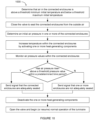
- a method for performing a test to determine whether an enclosure of a luminaire is adequately sealed includes closing an air valve to seal the enclosure from outside air and determining an initial air pressure in the enclosure. The method also includes activating a heat-generating component of the enclosure and waiting for a predetermined time period. The method further includes determining whether a current air pressure in the enclosure has increased from the initial air pressure by more than a threshold pressure change value and sending a signal indicating a result of the determination of whether the current air pressure in the enclosure has increased from the initial air pressure by more than a threshold pressure change value. The method still further includes deactivating the heat-generating component and opening the air valve.
- a luminaire or fixture
- Some fixtures may have sealed housings or semi-sealed housings with pressure equalization.
- Such fixtures may suffer from effects caused by the thermal operating cycle, as follows. When an automated luminaire is turned on, internal systems such as light sources, electronic circuits, power supplies, and motors generate heat and cause the temperature inside the fixture to rise. Such a rise in temperature produces a corresponding increase in the air pressure within the luminaire.
- this pressure is contained within the luminaire using hermetic seals.
- the load on such a hermetic seal from such a pressure increase within the luminaire can be significant and the repair and maintenance of the seals may be expensive and/or difficult.
- a failure in such seals may lead to water ingress into the luminaire, which may lead to damage or degradation of the luminaire mechanisms and/or optical systems.
- Luminaires according to the disclosure are sealed, but also are vented to the outside air through a system that removes excess humidity from incoming air and reduces condensation within the luminaire. This has the advantage of reducing water ingress to the luminaire and condensation within the luminaire, as well as reducing damage or degradation of the luminaire mechanisms and/or optical systems.
- FIG 1 presents a schematic view of a luminaire system 10 according to the disclosure.
- the luminaire system 10 includes a plurality of luminaires 12 according to the disclosure.
- the luminaires 12 each contains on-board a light source, one or more of color changing systems, light modulation devices, and pan and/or tilt systems to control an orientation of a head of the luminaire 12.
- Mechanical drive systems to control parameters of the luminaire 12 include motors or other suitable actuators coupled to a control system, as described in more detail with reference to Figure 6 , which is configured to control the motors or other actuators.
- the luminaire 200 includes three enclosures, in other embodiments any number of enclosures may be included.
- a light bar or cyclorama luminaire may have only the head enclosure 206 mounted for tilt motion relative to the base enclosure 202.
- the motors and associated electronic circuits that control tilt motion of such a luminaire may be located in either or both of the base enclosure 202 and/or the head enclosure 206.
- Still other embodiments may include only a single enclosure or more than three enclosures.
- the ability to increase the number of enclosures in a luminaire according to the disclosure provides the advantage of increasing the number of luminaire components that may be protected from damage or degradation caused by water ingress and/or condensation, while also allowing the additional components to rotate relative to each other. It is to be understood that when the phrase 'connected enclosures' is used in this specification, it means one or more enclosures.
- All three enclosures 202, 204, and 206 are sealed from external air such that external air does not pass through the seals. However, the enclosures 202, 204, and 206 are connected together and vented through drying tubes 212 and 214 that allow air to flow into and out of the enclosures, such that an internal air pressure in the enclosures 202, 204, and 206 never rises significantly above or below an external atmospheric pressure, thereby reducing pressure on the seals of the enclosures.
- the base enclosure 202 is vented to the motor enclosure 204 through a pipe 208 that couples an opening in the base enclosure 202 to an opening in the motor enclosure 204.
- the pipe 208 provides a rotatable sealed air coupling that is configured to pass air from the base enclosure 202 to the motor enclosure 204, sealed from the external air, through the rotating pan system at the base of the motor enclosure 204 by which the motor enclosure 204 rotates relative to the base enclosure 202.
- the motor enclosure 204 is vented to the head enclosure 206 through a pipe 217.
- the pipe 217 comprises a sealed air coupling at a first end 216 to an opening in the motor enclosure 204 and a rotating sealed air coupling at a second end 218 to an opening in the head enclosure 206.
- the pipe 217 is configured to pass air from the motor enclosure 204 to the head enclosure 206 through the rotating tilt system on the side of the head enclosure 206.
- the three enclosures 202, 204, and 206 are thus connected together by pipes 208 and 217 to form a combined enclosure having pressure and humidity control.
- the combined enclosure is vented to the external air through a vent pipe 209 via an opening in the head enclosure 206.
- the vent pipe 209 comprises a rotating sealed air coupling at a first end to the opening in the head enclosure 206.
- the vent pipe 209 comprises a sealed air coupling at a second end to a drying tube (or chamber) 212, which is sealed air coupled to a drying tube 214.
- the drying tubes 212 and 214 include a drying agent such as silica gel or other suitable desiccant material.
- An exit opening of the drying tube 214 includes a membrane 210 that air couples the drying tube 214 to the external air.
- both the temperature and internal air pressure rise within the three enclosures 202, 204, and 206. This increase in air pressure forces air out of the enclosures 202, 204, and 206 through the vent pipe 209 and drying tubes 212 and 214 before exiting the luminaire 200 at membrane 210.
- both the temperature and the internal air pressure inside the enclosures 202, 204, and 206 drop and external air may be drawn back into the luminaire 200 through the membrane 210, reducing or eliminating liquid water and/or moisture in the indrawn air. The indrawn air then passes through the drying tubes 212 and 214.
- the hot dry air being forced out when the luminaire 200 is powered on will regenerate the drying agent in the drying tubes, extending the life of the drying agent.
- this drying and regeneration process may be enhanced by using a heater (not shown in Figure 2 ) inside or around one or both of the drying tubes 212 and 214.
- one or more of the enclosures 202, 204, and 206 may include one or more sensors that are configured to measure characteristics of the enclosure, where the characteristics are selected from, but not limited to, air pressure, air humidity, and/or air temperature. Data samples from such sensors may be collected by a control system of the luminaire 200 and information related to the collected data samples sent (or transmitted) to a user via one or more communication channels such as a display included in the luminaire 200, the wired data link 14 using a protocol such as Remote Device Management (RDM), a web connection via the data link 14, a cellular or WiFi wireless connection, or a near-field communication (NFC) or other wireless communication link.
- RDM Remote Device Management
- NFC near-field communication
- Such sending of the information has the advantage of allowing a user of the luminaire 200 to obtain the information without opening the luminaire 200 or to receive the information at a remote location, rather than being required to access the luminaire 200 to obtain the information.
- a plurality of such data samples may be stored in a service log of the luminaire 200 and the contents of the log sent via one or more of the above channels to the user, a service technician, or the manufacturer.
- Such of a plurality of data samples in a service log has the advantage of giving a historical record of the sensed characteristics within the luminaire.
- the service log may also include one or more timestamps associated with corresponding one or more of the plurality of data samples, wherein a timestamp may indicate a time at which the data sample was collected.
- a timestamp may indicate a time at which the data sample was collected.
- the user, a service technician, or the manufacturer may identify a time at which a data sample of interest was collected.
- Figure 4 presents a schematic view of a luminaire humidity and pressure control system 400 according to the disclosure.
- Figure 4 is a simplified diagrammatic view of the luminaire humidity and pressure control system 400 of the luminaire 200 described with reference to Figure 2 .
- a base enclosure 402 is vented through a pipe 408 that connects the base enclosure 402 to a motor enclosure 404.
- the motor enclosure 404 is vented through a pipe 417 (having ends 416 and 418) that connects the motor enclosure 404 to a head enclosure 406.
- the three enclosures 402, 404, and 406 are thus connected together with tubing that creates a combined enclosure for pressure and humidity control.
- the head enclosure 406 is vented through a pipe 409, also venting the enclosures 402 and 404.
- Data samples from such sensors may be collected by the control system of the luminaire 200.
- the control circuit 426 is located in the base enclosure 402.
- a control circuit 428 may be additionally or alternatively located in the head enclosure 406.
- a control circuit (not shown in Figure 4 ) may be located in the motor enclosure 404.
- Such one or more control circuits may separately or cooperatively form the control system for the luminaire 200.
- Information related to the collected data samples may be sent to a user by the control system via one or more communication channels as described above.
- the data samples may include a timestamp and may be stored and sent to the user, a service technician, or the manufacturer.
- Figure 4 further shows a light source 420 external to the head enclosure 406.
- the light source 420 is optically and physically coupled to the head enclosure 406, but separated and sealed from the head enclosure 406 by a transparent window and gasket 421.
- Heat generated by the light source 420 may be significant, and such an arrangement provides the advantage of keeping heat emanating from the light source 420 external to the head enclosure 406 and helping to reduce the temperature rise and the air pressure rise within the head enclosure 406.
- Such reductions have the advantage of lessening the volume of air that exits and re-enters the combined enclosure of the three enclosures 402, 404, and 406 during each on/off cycle, helping to increase the life of the drying agent in drying tube 412.
- the drying boxes 226 and 228 are not part of the air cycle path described with reference to Figure 2 , which occurs when the luminaire 200 heats up and cools down. Instead the drying boxes 226 and 228 aid in initial assembly and subsequent maintenance.
- the drying boxes 226 and 228 include a drying agent such as silica gel and a plurality of openings in the box that expose the drying agent to the air in the enclosure. Once the enclosure is sealed, such boxes will remove some of the initial humidity captured within the enclosure, even before the luminaire is powered.
- the drying boxes 226 and 228 may also help ensure that air in the enclosures remain dry during storage and shipping.
- the drying agent inside any of the drying boxes 226 and 228 and/or the drying tubes 212 and 214 changes color when it absorbs moisture.
- the drying boxes 226 and 228 and/or the drying tubes 212 and 214 are configured to allow such color-changing drying agent to be easily visible.
- the drying boxes 226 and 228 and/or the drying tubes 212 and 214 may be fabricated at least in part of a transparent or translucent material.
- the drying box or drying tube may have an easy to remove portion of the box or tube exposing the drying agent to view.
- one or more of the plurality of openings in the drying box may be sized to allow viewing of the drying agent through the opening.
- Such a drying agent and drying boxes or drying tubes provide the advantage of enabling a user or service technician to visually check whether the drying agent is ready for use or needs regeneration or replacement before sealing the enclosures 202, 204, and 206 of the luminaire 200.
- the inclusion of the drying boxes 226 and 228 provides the advantage of an extra, initial drying cycle, which may serve to extend the life of the drying agents in the drying tubes within the luminaire.
- the inclusion of the drying boxes 226 and 228 provides the advantage of allowing the luminaire 200 to be placed back into service more quickly, without requiring the use of external tools to dehumidify the sealed enclosure or to flush the humid air from the sealed enclosure with nitrogen or dehumidified air.
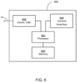
- the processor 602 is further electrically coupled to and in communication with a communication interface 606.
- the communication interface 606 is coupled to, and configured to communicate via, the data link 14.
- the processor 602 is also coupled via a control interface 608 to one or more sensors 424, motors, actuators, controls, heater 422, and/or other devices.
- the processor 602 is configured to receive control signals from the data link 14 via the communication interface 606 and, in response, to control systems and mechanisms of the luminaire 12 via the control interface 608.
- the processor 602 is further electrically coupled to and in communication with temperature, humidity, and/or pressure sensors such as the sensor 424.
- the processor 602 is configured to receive control signals from the data link 14 via the communication interface 606 and, in response, measure, store, and transmit information related to data sampled from one or more of the sensors 424.
- the control system 600 is suitable for implementing processes, module control, optical device control, pan and tilt movement, parameter control, motor control, position sensor control, brake control, and other functionality as disclosed herein, which may be implemented as instructions stored in the memory 604 and executed by the processor 602.
- the memory 604 comprises one or more disks and/or solid-state drives and may be used to store instructions and data that are read and written during program execution.
- the memory 604 may be volatile and/or non-volatile and may be read-only memory (ROM), random access memory (RAM), ternary content-addressable memory (TCAM), and/or static random-access memory (SRAM).
- FIG. 7 presents a first view of a luminaire 700 comprising a second luminaire humidity and pressure control system according to the disclosure.
- the second luminaire humidity and pressure control system is very similar to the luminaire humidity and pressure control system shown in Figure 2 , however it further includes a remotely operable air valve 719 configured to pass air when open and block air passage when closed.
- the valve 719 is positioned, in the embodiment shown in Figure 7 , between the drying tubes 212 and 214. Thus, when closed, the valve 719 is configured to block air passage between the connected enclosures 202, 204, and 206 and the drying tube 214 and the membrane 210.
- the connected enclosures 202, 204, and 206 are vented to the outside air through the valve 719.
- the valve 719 may be an electromagnetic valve that is electrically coupled to the control system of the luminaire 200, which may be configured to open and close the valve 719.
- Access panels and covers of the connected enclosures 202, 204, and 206 are configured with seals and, when the seals are functioning as intended, air flows into and out of the connected enclosures 202, 204, and 206 only through the valve 719.
- the valve 719 is closed, if air flows into or out of the connected enclosures 202, 204, and 206, it may be assumed that it is flowing through the seals.
- valve 719 is positioned between drying tubes 212 and 214, in other such embodiments the valve 719 may be positioned anywhere in the air path from the connected enclosures 202, 204, and 206 to the membrane 210.
- positioning the valve 719 with at least one of the drying tubes 212 and 214 between the valve 719 and the membrane 210 provides the benefit that, in such a position, the air passing through the valve 719 has been dried, which reduces the likelihood that condensation will form within the valve 719. The presence of such condensation when the ambient temperature falls below freezing could increase the likelihood that the valve 719 will freeze up and cease to function properly.
- Figure 8 presents a schematic view of the second luminaire humidity and pressure control system of Figure 7 .
- Figure 8 is a simplified diagrammatic view of the second luminaire humidity and pressure control system 800 of the luminaire 700.
- the second luminaire humidity and pressure control system 800 is very similar to the luminaire humidity and pressure control system 400 shown in Figure 4 , however the system 800 further includes a valve 819 positioned, in the embodiment shown in Figure 8 , between the head enclosure 406 and the drying tube 412.
- the valve 819 is an electromagnetic valve that is electrically coupled to the control system of the luminaire 700, which is configured to open and close the valve 819.
- the connected enclosures 402, 404, and 406 are sealed and, when the seals are functioning as intended, air flows into and out of the connected enclosures 402, 404, and 406 only through the valve 819.
- the valve 819 is closed, air should only flow into or out of the connected enclosures 402, 404, and 406, if at all, through the seals.
- valve 819 is positioned between the head enclosure 406 and the drying tube 412, in other such embodiments the valve 819 may be positioned anywhere in the air path from the connected enclosures 402, 404, and 406 to the membrane 410. However, as described above, positioning the valve 819 with the drying tube 412 between the valve 819 and the membrane 410 may reduce the likelihood that condensation will form within the valve 819.
- the valve 719 may be operated to seal the connected enclosures 202, 204, and 206 from the outside air so that pressure changes in one or more of the connected enclosures 202, 204, and 206 may be measured.
- Such measurement provides a test of whether the seals of the connected enclosures 202, 204, and 206 are adequately air-tight to permit the luminaire humidity and pressure control system 400 (or 800) to function as designed to reduce water ingress into the luminaire.
- test may be run to confirm that the luminaire 700 has been properly assembled.
- the test may also be run after maintenance is performed on the luminaire 700, where the maintenance requires that a technician (or other user) remove and reattach a sealed cover (or a sealed panel in a cover, both collectively referred to herein as a sealed cover) to access a component in one of the connected enclosures 202, 204, or 206.
- the test may be initiated by a control signal (such as a command) that is received via the data link 14 or via an input panel of the luminaire 700.
- a control signal such as a command
- a user may initiate the test at any time that the luminaire 700 is powered on.
- the control system 600 of the luminaire 700 may be configured to perform the test automatically when the luminaire 700 is initially powered up. Such configuration may be set by a user by a control signal received via the data link 14 or via the input panel of the luminaire 700.
- FIGS 9 and 10 respectively, present flow charts of first and second processes 900 and 1000 for testing seals in the second luminaire humidity and pressure control system according to the disclosure. Both processes 900 and 1000 begin with the following steps:
- the process 1000 continues with the following steps:
- the threshold minimum initial temperature in the one or more of the connected enclosures 202, 204, and 206 is 0° C. In some embodiments, the threshold maximum initial temperature in the one or more of the connected enclosures 202, 204, and 206 is 55° C. In such embodiments, the temperature may rise to 70-75° C during the test. In general, the threshold maximum initial temperature will be at least 10-15° C less than the temperature achieved once the heat-generating components have been activated. The threshold maximum initial temperature may be selected based on where in the connected enclosures 202, 204, and 206 the one or more temperature sensors are located.
- the signal indicating a result of the test is sent as a message over a communication link, such as data link 14.
- the signal is sent as an indicator or status display on the luminaire 700.
- the signal is sent using both methods.
- the test sequence is performed every time the luminaire 700 is initially powered up. In some embodiments, the test sequence is performed in response to a signal received from a user, such as a command received via an input panel of the luminaire 700 or via a communication link, such as the data link 14 or a wireless communication link. In some embodiments, as a user-selectable option, the control system of the luminaire 700 does not begin normal operation if the connected enclosures 202, 204, and 206 are not adequately sealed.
Landscapes
- Engineering & Computer Science (AREA)
- General Engineering & Computer Science (AREA)
- Chemical & Material Sciences (AREA)
- Analytical Chemistry (AREA)
- General Chemical & Material Sciences (AREA)
- Oil, Petroleum & Natural Gas (AREA)
- Chemical Kinetics & Catalysis (AREA)
- Arrangement Of Elements, Cooling, Sealing, Or The Like Of Lighting Devices (AREA)
- Examining Or Testing Airtightness (AREA)
Applications Claiming Priority (3)
| Application Number | Priority Date | Filing Date | Title |
|---|---|---|---|
| US17/851,742 US11549679B2 (en) | 2022-06-28 | 2022-06-28 | System and method for controlling the humidity and pressure in a luminaire |
| US202217901231A | 2022-09-01 | 2022-09-01 | |
| EP22201083.7A EP4299980B1 (fr) | 2022-06-28 | 2022-10-12 | Système et procédé de régulation de l'humidité et de la pression dans un luminaire |
Related Parent Applications (2)
| Application Number | Title | Priority Date | Filing Date |
|---|---|---|---|
| EP22201083.7A Division-Into EP4299980B1 (fr) | 2022-06-28 | 2022-10-12 | Système et procédé de régulation de l'humidité et de la pression dans un luminaire |
| EP22201083.7A Division EP4299980B1 (fr) | 2022-06-28 | 2022-10-12 | Système et procédé de régulation de l'humidité et de la pression dans un luminaire |
Publications (2)
| Publication Number | Publication Date |
|---|---|
| EP4579128A2 true EP4579128A2 (fr) | 2025-07-02 |
| EP4579128A3 EP4579128A3 (fr) | 2025-08-27 |
Family
ID=83691300
Family Applications (2)
| Application Number | Title | Priority Date | Filing Date |
|---|---|---|---|
| EP25177139.0A Pending EP4579128A3 (fr) | 2022-06-28 | 2022-10-12 | Système et procédé de régulation de l'humidité et de la pression dans un luminaire |
| EP22201083.7A Active EP4299980B1 (fr) | 2022-06-28 | 2022-10-12 | Système et procédé de régulation de l'humidité et de la pression dans un luminaire |
Family Applications After (1)
| Application Number | Title | Priority Date | Filing Date |
|---|---|---|---|
| EP22201083.7A Active EP4299980B1 (fr) | 2022-06-28 | 2022-10-12 | Système et procédé de régulation de l'humidité et de la pression dans un luminaire |
Country Status (2)
| Country | Link |
|---|---|
| EP (2) | EP4579128A3 (fr) |
| CN (1) | CN120627005A (fr) |
Families Citing this family (1)
| Publication number | Priority date | Publication date | Assignee | Title |
|---|---|---|---|---|
| CN222703273U (zh) * | 2024-04-29 | 2025-04-01 | 广州市浩洋电子股份有限公司 | 一种具有气密性自测功能的灯具 |
Family Cites Families (6)
| Publication number | Priority date | Publication date | Assignee | Title |
|---|---|---|---|---|
| DE102006028295B4 (de) * | 2006-06-20 | 2010-01-14 | Behr Gmbh & Co. Kg | Scheinwerfer für ein Fahrzeug mit einer Feuchteaufnahmeeinrichtung |
| US10156372B2 (en) * | 2015-06-09 | 2018-12-18 | W.L. Gore & Associates, Inc. | Moisture pump for enclosure |
| CN108603655B (zh) * | 2015-12-28 | 2021-01-05 | 昕诺飞控股有限公司 | 具有单个压力空腔的led照明装置 |
| CN106907684B (zh) * | 2017-04-06 | 2020-06-30 | 广东盛世飞扬光电科技有限公司 | 一种户外防水摇头灯 |
| CN110657366A (zh) * | 2019-08-12 | 2020-01-07 | 扬州卓一光电科技有限公司 | 一种具有除湿功能的使用便捷的投光灯 |
| CN212081085U (zh) * | 2020-05-08 | 2020-12-04 | 江苏顺天灯业钢杆制造有限公司 | 一种高密封性的防水性led路灯 |
-
2022
- 2022-10-12 CN CN202510978427.7A patent/CN120627005A/zh active Pending
- 2022-10-12 EP EP25177139.0A patent/EP4579128A3/fr active Pending
- 2022-10-12 EP EP22201083.7A patent/EP4299980B1/fr active Active
Also Published As
| Publication number | Publication date |
|---|---|
| CN120627005A (zh) | 2025-09-12 |
| EP4299980B1 (fr) | 2025-07-02 |
| EP4579128A3 (fr) | 2025-08-27 |
| EP4299980A1 (fr) | 2024-01-03 |
Similar Documents
| Publication | Publication Date | Title |
|---|---|---|
| US11549679B2 (en) | System and method for controlling the humidity and pressure in a luminaire | |
| US10587785B2 (en) | Monitoring camera and condensation suppressing method | |
| US20240410559A1 (en) | System and Method for Controlling the Humidity and Pressure in a Luminaire | |
| US6579168B1 (en) | Back-up DC vent system for equipment enclosure | |
| US7699506B2 (en) | Silent moving head projector | |
| US10197892B2 (en) | Image pickup apparatus resistant to environments, and image monitoring system | |
| CN101978319A (zh) | 投影仪 | |
| EP3307419B1 (fr) | Pompe à humidité pour enceinte | |
| EP4299980B1 (fr) | Système et procédé de régulation de l'humidité et de la pression dans un luminaire | |
| CN110289563A (zh) | 一种带有智能检测的开关柜 | |
| JP2009517628A (ja) | 温度調節手段を備えた積分球 | |
| JP7007315B2 (ja) | 監視カメラおよび監視カメラの結露抑制方法 | |
| JP7222907B2 (ja) | 閉じた車両のヘッドランプのハウジングを除湿するために使用されるか、または閉じたハウジング内で湿気が発生するのを防ぐのに適した装置 | |
| HK40115809A (en) | System and method for controlling the humidity and pressure in a luminaire | |
| KR101408366B1 (ko) | 촬영 장치 및 촬영 장치의 제습 방법 | |
| CN117308063A (zh) | 用于控制照明装置中湿度和压力的系统和方法 | |
| CN114659166B (zh) | 空调的室内机 | |
| CN110243018B (zh) | 空调机的室内机 | |
| US20070188094A1 (en) | Device for controlling the atmosphere in a space | |
| CN108387507B (zh) | 双温度控制老化试验装置 | |
| CN214536603U (zh) | 模块化数据中心天窗系统 | |
| CN106765816A (zh) | 一种兼具逃生功能的管廊智能通风系统 | |
| CN117336585A (zh) | 具有保温防霜功能的摄像装置及系统 | |
| CN221887015U (zh) | 自干燥式电子设备 | |
| CN112305850A (zh) | 一种客厅ai投影灯及其投影方法 |
Legal Events
| Date | Code | Title | Description |
|---|---|---|---|
| PUAI | Public reference made under article 153(3) epc to a published international application that has entered the european phase |
Free format text: ORIGINAL CODE: 0009012 |
|
| STAA | Information on the status of an ep patent application or granted ep patent |
Free format text: STATUS: REQUEST FOR EXAMINATION WAS MADE |
|
| 17P | Request for examination filed |
Effective date: 20250516 |
|
| AC | Divisional application: reference to earlier application |
Ref document number: 4299980 Country of ref document: EP Kind code of ref document: P |
|
| AK | Designated contracting states |
Kind code of ref document: A2 Designated state(s): AL AT BE BG CH CY CZ DE DK EE ES FI FR GB GR HR HU IE IS IT LI LT LU LV MC ME MK MT NL NO PL PT RO RS SE SI SK SM TR |
|
| REG | Reference to a national code |
Ref country code: DE Ref legal event code: R079 Free format text: PREVIOUS MAIN CLASS: F21V0031000000 Ipc: F21V0031030000 |
|
| PUAL | Search report despatched |
Free format text: ORIGINAL CODE: 0009013 |
|
| AK | Designated contracting states |
Kind code of ref document: A3 Designated state(s): AL AT BE BG CH CY CZ DE DK EE ES FI FR GB GR HR HU IE IS IT LI LT LU LV MC ME MK MT NL NO PL PT RO RS SE SI SK SM TR |
|
| RIC1 | Information provided on ipc code assigned before grant |
Ipc: F21V 31/03 20060101AFI20250724BHEP Ipc: F21V 21/30 20060101ALI20250724BHEP Ipc: F21V 23/04 20060101ALI20250724BHEP Ipc: F21V 31/00 20060101ALI20250724BHEP Ipc: F21Y 115/10 20160101ALN20250724BHEP Ipc: F21W 131/406 20060101ALN20250724BHEP |