EP4579132A1 - Cuisinière multi-usages portative - Google Patents
Cuisinière multi-usages portative Download PDFInfo
- Publication number
- EP4579132A1 EP4579132A1 EP23856766.3A EP23856766A EP4579132A1 EP 4579132 A1 EP4579132 A1 EP 4579132A1 EP 23856766 A EP23856766 A EP 23856766A EP 4579132 A1 EP4579132 A1 EP 4579132A1
- Authority
- EP
- European Patent Office
- Prior art keywords
- combustion chamber
- opening
- combustion
- cooker
- gases
- Prior art date
- Legal status (The legal status is an assumption and is not a legal conclusion. Google has not performed a legal analysis and makes no representation as to the accuracy of the status listed.)
- Pending
Links
Images




Classifications
-
- F—MECHANICAL ENGINEERING; LIGHTING; HEATING; WEAPONS; BLASTING
- F23—COMBUSTION APPARATUS; COMBUSTION PROCESSES
- F23B—METHODS OR APPARATUS FOR COMBUSTION USING ONLY SOLID FUEL
- F23B10/00—Combustion apparatus characterised by the combination of two or more combustion chambers
- F23B10/02—Combustion apparatus characterised by the combination of two or more combustion chambers including separate secondary combustion chambers
-
- F—MECHANICAL ENGINEERING; LIGHTING; HEATING; WEAPONS; BLASTING
- F23—COMBUSTION APPARATUS; COMBUSTION PROCESSES
- F23B—METHODS OR APPARATUS FOR COMBUSTION USING ONLY SOLID FUEL
- F23B20/00—Combustion apparatus specially adapted for portability or transportability
-
- F—MECHANICAL ENGINEERING; LIGHTING; HEATING; WEAPONS; BLASTING
- F23—COMBUSTION APPARATUS; COMBUSTION PROCESSES
- F23J—REMOVAL OR TREATMENT OF COMBUSTION PRODUCTS OR COMBUSTION RESIDUES; FLUES
- F23J11/00—Devices for conducting smoke or fumes, e.g. flues
- F23J11/08—Devices for conducting smoke or fumes, e.g. flues for portable apparatus
-
- F—MECHANICAL ENGINEERING; LIGHTING; HEATING; WEAPONS; BLASTING
- F23—COMBUSTION APPARATUS; COMBUSTION PROCESSES
- F23L—SUPPLYING AIR OR NON-COMBUSTIBLE LIQUIDS OR GASES TO COMBUSTION APPARATUS IN GENERAL ; VALVES OR DAMPERS SPECIALLY ADAPTED FOR CONTROLLING AIR SUPPLY OR DRAUGHT IN COMBUSTION APPARATUS; INDUCING DRAUGHT IN COMBUSTION APPARATUS; TOPS FOR CHIMNEYS OR VENTILATING SHAFTS; TERMINALS FOR FLUES
- F23L11/00—Arrangements of valves or dampers after the fire
-
- F—MECHANICAL ENGINEERING; LIGHTING; HEATING; WEAPONS; BLASTING
- F23—COMBUSTION APPARATUS; COMBUSTION PROCESSES
- F23L—SUPPLYING AIR OR NON-COMBUSTIBLE LIQUIDS OR GASES TO COMBUSTION APPARATUS IN GENERAL ; VALVES OR DAMPERS SPECIALLY ADAPTED FOR CONTROLLING AIR SUPPLY OR DRAUGHT IN COMBUSTION APPARATUS; INDUCING DRAUGHT IN COMBUSTION APPARATUS; TOPS FOR CHIMNEYS OR VENTILATING SHAFTS; TERMINALS FOR FLUES
- F23L13/00—Construction of valves or dampers for controlling air supply or draught
- F23L13/02—Construction of valves or dampers for controlling air supply or draught pivoted about a single axis but having not other movement
-
- F—MECHANICAL ENGINEERING; LIGHTING; HEATING; WEAPONS; BLASTING
- F24—HEATING; RANGES; VENTILATING
- F24B—DOMESTIC STOVES OR RANGES FOR SOLID FUELS; IMPLEMENTS FOR USE IN CONNECTION WITH STOVES OR RANGES
- F24B1/00—Stoves or ranges
- F24B1/20—Ranges
- F24B1/202—Ranges specially adapted for travelling
-
- F—MECHANICAL ENGINEERING; LIGHTING; HEATING; WEAPONS; BLASTING
- F24—HEATING; RANGES; VENTILATING
- F24B—DOMESTIC STOVES OR RANGES FOR SOLID FUELS; IMPLEMENTS FOR USE IN CONNECTION WITH STOVES OR RANGES
- F24B1/00—Stoves or ranges
- F24B1/20—Ranges
- F24B1/22—Ranges in which the baking oven is arranged above the fire-box
-
- F—MECHANICAL ENGINEERING; LIGHTING; HEATING; WEAPONS; BLASTING
- F24—HEATING; RANGES; VENTILATING
- F24B—DOMESTIC STOVES OR RANGES FOR SOLID FUELS; IMPLEMENTS FOR USE IN CONNECTION WITH STOVES OR RANGES
- F24B5/00—Combustion-air or flue-gas circulation in or around stoves or ranges
- F24B5/06—Combustion-air or flue-gas circulation in or around stoves or ranges in or around ranges
-
- F—MECHANICAL ENGINEERING; LIGHTING; HEATING; WEAPONS; BLASTING
- F24—HEATING; RANGES; VENTILATING
- F24B—DOMESTIC STOVES OR RANGES FOR SOLID FUELS; IMPLEMENTS FOR USE IN CONNECTION WITH STOVES OR RANGES
- F24B9/00—Stoves, ranges or flue-gas ducts, with additional provisions for heating water
- F24B9/006—Stoves, ranges or flue-gas ducts, with additional provisions for heating water flue-gas ducts
-
- F—MECHANICAL ENGINEERING; LIGHTING; HEATING; WEAPONS; BLASTING
- F24—HEATING; RANGES; VENTILATING
- F24B—DOMESTIC STOVES OR RANGES FOR SOLID FUELS; IMPLEMENTS FOR USE IN CONNECTION WITH STOVES OR RANGES
- F24B13/00—Details solely applicable to stoves or ranges burning solid fuels
- F24B13/04—Arrangements for feeding solid fuel, e.g. hoppers
Definitions
- the present invention relates to a multi-purpose cooker.
- Particular embodiments of the present invention relate to a portable cooker.
- the cooker may be suitable for indoor as well as outdoor use.
- “Rocket stoves” are mainly used for outdoor cooking or sometimes as simple stoves. They are devices that use a compartment through which the fuel is introduced, the fuel remaining in the lower part of an elongated combustion chamber, above which there is an opening that allows hot air to escape at a high temperature (even in the form of a flame). Once a suitable temperature has been reached, the thin elongated shape of the combustion chamber facilitates combustion of the particles raised by the gases produced by the fuel, so that fairly efficient combustion is achieved, achieving high temperatures with very little residual smoke.
- “Rocket Stoves” for use in cooking are well known and comprise a support for the base of a frying pan or pot on top of the combustion chamber, so that its base receives the flame directly.
- Bilbao Stove which is usually much larger.
- This usually has a hearth in the lower part, either in the centre or to one side, and the upper part comprises a flat surface with a certain number of holes.
- This configuration creates something very similar to today's cooking ranges, in different sizes.
- Bilbao stoves are also known in which the hobs consist of a set of concentric rings, which can leave a small open hole in the centre. This hole can be made larger or smaller by removing or adding rings, allowing the flame or gases to contact the cooking utensil on the cooker directly.
- Bilbao stoves are not designed to be portable, as they are usually designed for indoor use and, for this purpose, require a fixed installation for the smoke outlet, i.e. a built-in chimney. In the same way as with "Rocket Stoves", the intensity of the fire is also difficult to regulate in Bilbao stoves.
- the present invention discloses a portable multi-purpose cooker comprising a burner with a first combustion chamber, an ash pan for collecting ash located below said first combustion chamber, a cooking zone located above the burner and a flue for exhaust of the combustion gases produced in the burner.
- the cooking zone comprises a worktop which, in turn, comprises at least one hob heated by combustion gases from the burner.
- the first combustion chamber comprises a first air inlet, a first opening for horizontal loading of fuel and a second opening for the vertical loading of fuel.
- the cooker also comprises a frame enclosing the burner and supporting the components of the cooker.
- the burner comprises a second combustion chamber of a vertical tubular shape, the second combustion chamber being located between the first combustion chamber and the cooking zone.
- the second combustion chamber comprises at least a second air inlet, a first combustion gas outlet leading to the cooking zone and a second combustion gas outlet leading to a first bypass duct connecting an upper end of the second combustion chamber to the flue without passing through the hob.
- the cooker comprises means for regulating the quantity of combustion gases reaching the cooking zone.
- the burner has a double combustion chamber provides a better and more complete reaction of the fuel, so that the amount of suspended fuel particles in the combustion gases is greatly reduced.
- the second combustion not only is it possible to reuse the suspended particles and obtain more heating capacity and thus greater efficiency, but gases that are toxic to humans and animals, such as carbon monoxide, are also eliminated.
- the air can leave the second combustion zone through two different outlets.
- the first outlet leads the flame or combustion gases to the cooking zone, which are used to heat utensils and/or food, and the second outlet goes to the first bypass duct, which leads directly to the flue.
- the frame has several functions. The first is a structural function, giving solidity to the cooker. The second is a design function.
- the design derives not only from a desired appearance and structural necessity, but also the desired thermal efficiency. Factors to take into account when designing the frame for good thermal efficiency are, among others, the combustion inside the burner, the channelling of the flame or combustion gases and possible heat transfer losses.
- the shape of the burner is determined by said combustion channelling and the efficiency of combustion, while the frame is consistent with this shape and its structural integrity. For the efficiency and the optimisation of structure and materials, external appearance may substantially reflect the interior design.
- the means for regulating the quantity of combustion gases reaching the cooking zone regulates the passage of said gases to the cooker, allowing much greater control of the heat and thermal energy emanating from the cooker and thus the variability of the heat output applied to the food without the need to modify the burner's fire, either through a frying pan, directly or in any other way.
- an ash compartment or ash pan below the first combustion chamber is an ash compartment or ash pan.
- This ash pan may be separated from the combustion chamber by a grate, which allows only the residual ash from the fuel that is smaller than the spaces formed by the grate to fall through.
- This ash pan may be accessed through an opening so that the ash can be removed when necessary to avoid choking the fire.
- the means for regulating the quantity of combustion gases reaching the cooking zone comprises a valve.
- This valve is in the form of a plate that gradually rotates relative to an axis between a maximum angular position covering the outlet of the first bypass duct, and a minimum angular position covering the outlet to the cooking zone. In this way, the valve directs the gases from the second combustion chamber towards the cooking zone or the bypass duct according to its position.
- the valve is the element that enables control or regulation of the amount of combustion gases that reach the cooker, which is a great help for being able to cook according to the recipe or food.
- the plate directs the flow of combustion gases.
- the plate may either block the outlet to the cooking zone completely, which forces all the combustion gases to pass through the first bypass duct, or block the outlet of the first bypass duct, which forces all the combustion gases to pass through the cooking zone.
- Being able to regulate the thermal energy transferred to the utensils or to the food provides the invention with great versatility, allowing much greater control of the heat applied at any given moment and thus responsiveness for complex cooking recipes.
- the plate may be fixed at at least one intermediate point of its pivot angle, so that the first and second outlets are open and the combustion gas flow is distributed between each outlet in a manner equivalent to the opening ratio of each outlet.
- the plate With the plate at an intermediate point between the two positions of maximum and minimum angle, the plate allows the gases to pass in both directions, distributing the total flow of combustion gases between the outlet for the cooking zone and the outlet for the first bypass duct. This distribution is in relation to the proportions between the openings for each outlet.
- the plate has a number of positions in which it may be fixed along its rotational path.
- the practicable door for closing off the first horizontal refuelling opening is a side door that opens or closes off access to the first combustion chamber through the first horizontal refuelling opening.
- This door allows the burner to be opened or closed as desired, providing the ability to add further fuel horizontally and to a large extent stoke the fire when opening it, and to reduce heat losses and smother the fire if necessary when in the closed position.
- the second opening for vertical fuel loading allows for the attachment of a hopper.
- Fuel may be loaded vertically either manually or by gravity, as the flap and second opening are configured to be able to accommodate, for example, a hopper. This allows a constant supply of fuel to the fire, thus achieving a stable output of heat over time.
- the cooker comprises a handle for pulling or pushing the cooker to improve its portability.
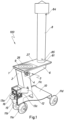
- Figure 1 shows an embodiment of the portable multi-purpose cooker 100.
- the figure shows the various external elements that make up this embodiment.
- a cooking zone 1 with a worktop 27 comprising a hob 9 in the shape of a hole and rings 26 that restrict or cover the hole in hob 9.
- Said rings 26 can easily be removed so as to be able to provide hob 9 with different sizes and make it adjustable to different sizes of utensils to be used for cooking.
- Located below cooking zone 1 is the means for regulating the quantity of combustion gases 3 reaching the cooking zone.
- said means 3 has the appearance of a potentiometer, but other options are possible.
- Connected to worktop 27 via a smoke outlet socket 81 is a flue 8 for the escape of smoke.
- a flame viewing window 13b On one side surface of frame 4 surrounding burner 2 there is a flame viewing window 13b, while at the front there is a practicable door 15 giving access to an ash pan, a door 14 for access to horizontal fuel loading comprising a flame viewing window 13a and a first adjustable air inlet 16 to burner 2.
- a flap 12 On another upper horizontal surface of the lower part of burner 2, there is a flap 12 giving access to burner 2 for vertical fuel loading.
- This figure also shows two projections 84 and 85 on flue 8 for attaching a heat accumulator (not shown).
- FIG. 2 shows in detail burner 2 covered by frame 4 and the different entrances to burner 2.
- burner 2 comprises a first combustion chamber 21 in a horizontal position, which can be accessed through different entrances.
- first entrance 19 for horizontal fuel loading which can be opened and closed by means of door 14 located on the front surface of first combustion chamber 21
- a second entrance 17 for vertical fuel loading which can be opened or closed by means of flap 12 located on a surface above first combustion chamber 21.
- ash pan 5 located below first combustion chamber 21, partly separated from first combustion chamber 21 by a grate 205. Grate 205 allows ash to pass through once it has been reduced to a size small enough to slip between its openings.
- Ash from combustion is stored in ash pan 5 until the user needs or wants to remove them.
- Ash pan 5 is accessible through a hatch 15 which can be opened and closed.
- a first adjustable air inlet 16 that allows air to pass to the burner to provide draught if the fire needs it.
- Door 14 also has a flame viewing window 13a so that the fire can be observed from the front. Also visible in this view are a secondary opening 18b of a second air inlet, the front wheels 11a and 11b of cooker 100 attached to frame 4 and surface 10.
- Figure 3 shows a perspective view with the side wall of frame 4 removed, so that the inner walls of burner 2 can be seen.
- first combustion chamber 21 and second combustion chamber 22 of vertical tubular shape clearly allows first combustion chamber 21 and second combustion chamber 22 of vertical tubular shape to be distinguished and shows a secondary air duct 28a located between an outer side wall (not seen) of frame 4 and the wall of burner 2, and following the path of first combustion chamber 21, so that air can enter from the outside through a secondary opening 18a of a second air inlet until it reaches openings 23a and 23b located at the bottom of the second combustion chamber 22 and at the top of first combustion chamber 21 respectively.
- burner 2 is surrounded by thermal insulating material 29 located between said burner 2 and the outer walls of frame 4.
- this structure may be symmetrical and comprise another secondary air duct and openings on the opposite side of burner 2, although having it on only one side, the one shown in this figure or the opposite side, is also entirely possible and functional.
- This figure also shows many of the elements mentioned and shown previously, such as flap 12, flame viewing windows 13a and 13b, door 14, hatch 15, first adjustable air inlet 16, ash pan 5, surface 10 and front wheels 11a and 11b.
- FIG. 4 shows a detail view of cooking zone 1 and the means for regulating the quantity of combustion gases 3 reaching the cooking zone, which are located at an upper end of the burner's second combustion chamber.
- said means 3 comprises a strength indicator 25 in the form of a plate attached to frame 4 and a handle 24 which offers a secure grip to act on means 3 to regulate the fire.
- rings 26 can be seen on hob 9 located on worktop 27.
- First bypass duct 6 can be seen beneath worktop 27 and adjacent to means 3.
- second inlet 17 for vertical fuel loading the interior of first combustion chamber 21, viewing window 13b and surface 10 for depositing cooking utensils can also be seen.
- Figure 5 shows a very similar figure to the previous one, but the outer side wall of frame 4 and strength indicator plate 25 of means 3 have been hidden, so that the internal elements of cooker 100 can be seen. This helps to better understand the operation of means 3 in particular.
- said means 3 is located at the end, or upper part, of the second combustion chamber, so that hot gases or flames reach it from below, and it is at this point that a valve 30 in the form of a plate with the ability to rotate with respect to an axis allows said gases to pass in one direction or another depending on its position. If valve 30 is in a substantially horizontal position, it covers first outlet 201 towards cooking zone 1 by allowing passage or guiding of all the gases towards second outlet 206 towards first bypass duct 6.
- valve 30 If, on the other hand, valve 30 is in a substantially vertical position, then it closes off second outlet 206 towards first bypass duct 6, allowing all the flow of combustion gases to pass through first outlet 201 towards cooking zone 1, so that they reach hob 9. If valve 30 is in an intermediate position, the flow of combustion gases is guided towards both outlets 201 and 206 with a flow rate proportional to the opening left in each outlet 201 and 206 by valve 30.
- some of the other elements already mentioned, such as worktop 27, thermal insulating material 29 between second combustion chamber 22 and frame 4, flap 12, handle 24 of means 3, surface 10 for depositing cooking utensils, second inlet 17 for the vertical loading of fuel and even a rear wheel 11c, can also be seen.
- Figure 6 shows a cross-section view of cooker 100 in side elevation. This figure makes it possible to see the internal configuration of cooker 100, to identify the various internal components and, at the same time, to point out the whole path 121 of the gases produced by combustion.
- This path 121 originates where the fuel is located, that is near fuel loading inlets 17 and 19 in first combustion chamber 21, either the horizontal loading inlet or the vertical loading inlet, which are accessed through door 14 and flap 12 respectively.
- Fresh air can join this combustion through adjustable air inlet 16.
- ash pan 5 Directly below this area, separated by a grate 205, is ash pan 5, which is accessed through door 15.
- first combustion chamber 21 moves substantially laterally through first combustion chamber 21 to a more inward zone driven by the draught provided by the flue and the difference in pressures inside and outside the burner.
- the flow of combustion gases reaches the junction between first combustion chamber 21 and second combustion chamber 22, where there is a constriction 20 through which the combustion gases pass.
- This causes a Venturi effect, further amplifying the pressure difference, which in turn causes air to be sucked in through openings 23a located in the lower or initial area of second combustion chamber 22.
- This suction of air draws in air from outside through secondary opening 18a, this air from outside passing through secondary air duct 28a.
- openings 23a and 23b being one on each side of and adjacent to constriction 20 and being in turn connected to the same secondary duct 28a, means that the suction through openings 23a achieved by the Venturi effect also causes a quantity of the outside air passing through secondary duct 28a to reach first combustion chamber 21 before the constriction. In this way, said quantity of preheated and oxygenated air is mixed with the combustion gases before reaching second combustion chamber 22. On the other hand, another quantity of the preheated and oxygenated air arrives directly into second combustion chamber 22.
- valve 30 directs the gases or flame to first outlet 201, towards the cooking zone 1 and/or to second outlet 206 towards first bypass duct 6. If one of the two outlets 201 or 206 is blocked by valve 30, the entire flow exits through the other outlet. If valve 30 is in an intermediate position, as shown in the figure, the flow is divided between the two outlets 201 and 206 in proportion to the openings left to each outlet by valve 30.
- first bypass duct 6 follows the path of the first bypass duct 6 and reaches socket 81, which guides it towards flue 8 for discharge of the flue gas.
- These combustion gases will not contribute to the cooking of any food, so that the strength of the heat in cooking zone 1 is controlled by means 3 causing valve 30 to divert some of the thermal energy of combustion by reducing the flow of gases reaching this zone.
- the thermal energy contained in this quantity of gases diverted towards first bypass duct 6 is utilised once it reaches flue 8 for the escape of smoke by coming into contact with heat exchanger 83 located within flue 8.
- the flow of gases that reaches cooking zone 1 either exits directly through the opening that makes up hob 9 and/or possible rings 26 located therein, thus heating any utensil that is located above hob 9, or the latter is covered by the rings, heating said rings 26, which in turn transfer the heat to the utensil placed above said rings 26 when in direct contact.
- this heat transfer may be direct by convection, the flow of gases passing through the opening and coming into contact with the utensil, or indirect, the flow of gases meeting rings 26, which completely cover the opening of the hob 9, heating said rings 26 by convection and said rings transferring the heat by conduction to the utensil placed on top of them.
- a third duct 40 is provided to collect the residual gases that pass beneath worktop 27 and is configured in parallel with first bypass duct 6.
- This third duct 40 for collecting the residual gases flows into the end of first duct 6, which in turn will guide the flow of residual gases towards flue 8, thus ensuring that the waste heat in the gases is reused with the heat exchanger 83.
- the flow coming from first duct 6 and third duct 40 continues on its upwards route due to the pressure difference and exits from the top of flue 8.
- This figure also shows elements such as thermal insulation 29 between the walls of burner 2 and frame 4, surface 10 for the storage of cooking utensils, flap 12 and wheels 11b and 11c.
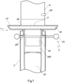
- Figure 7 shows a cross-section view in front elevation from which it is possible to see from another angle the end or upper area of second combustion chamber 22, where means 3 acts through valve 30 and the components of cooking zone 1. This angle helps to provide a better view of the interior of cooking zone 1 and third duct 40 under worktop 27. Furthermore, as valve 30 is in an intermediate position, it offers access to first outlet 201 located above valve 30 and to second outlet 206, which can be seen to be located behind the valve 30. This figure also shows frame 4, the handle 24 of means 3, rings 26, hob 9, flue 8 and even a projection 85 from heat exchanger 83 (not shown) for coupling the heat accumulator (not shown).
- FIG. 9 shows a detail view of hopper 300 which can be attached to cooker 100.
- Hopper 300 comprises a tank 31 of square cross-section in which fuel is stored, for example pellets or olive stones, a lid 32, a funnel 33 that ends in a passage 34 that connects with the first combustion chamber, a regulation handle 35 that regulates the position of a plate (not shown) by means of a thread as a horizontal slide that allows or does not allow fuel to pass towards the combustion chamber.
- Hopper 300 also comprises a platform 37 which engages and seals second inlet 17, a tube 38 of square cross-section with openings 313a, 313b and 313c for viewing the fire and bars 39 for collecting the fuel in pellet form as it falls through passage 34.
- Openings 313a, 313b and 313c may be covered with ceramic glass, so as to allow the fire to be viewed through viewing windows 13a, 13b and 13c, but not allow the passage or back-flow of air. Opening 313a may not even be present, so that the fire cannot be seen through viewing window 13a and may only be seen through viewing windows 13b and 13c when hopper 300 is attached.
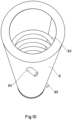
- Figure 10 shows a detail view of flue 8 for the escape of smoke with heat exchanger 83 in the form of a coil installed within it, with projections 84 and 85 for connecting the heat accumulator (not shown) and providing an inlet and outlet for a flow responsible for collecting this heat to be accumulated in the form of thermal energy.
Landscapes
- Engineering & Computer Science (AREA)
- Chemical & Material Sciences (AREA)
- Combustion & Propulsion (AREA)
- Mechanical Engineering (AREA)
- General Engineering & Computer Science (AREA)
- Physics & Mathematics (AREA)
- Thermal Sciences (AREA)
- Solid-Fuel Combustion (AREA)
- Baking, Grill, Roasting (AREA)
Applications Claiming Priority (2)
| Application Number | Priority Date | Filing Date | Title |
|---|---|---|---|
| ES202231404U ES1295615Y (es) | 2022-08-25 | 2022-08-25 | Cocina multiusos portable |
| PCT/ES2023/070521 WO2024042258A1 (fr) | 2022-08-25 | 2023-08-21 | Cuisinière multi-usages portative |
Publications (1)
| Publication Number | Publication Date |
|---|---|
| EP4579132A1 true EP4579132A1 (fr) | 2025-07-02 |
Family
ID=84100485
Family Applications (1)
| Application Number | Title | Priority Date | Filing Date |
|---|---|---|---|
| EP23856766.3A Pending EP4579132A1 (fr) | 2022-08-25 | 2023-08-21 | Cuisinière multi-usages portative |
Country Status (3)
| Country | Link |
|---|---|
| EP (1) | EP4579132A1 (fr) |
| ES (1) | ES1295615Y (fr) |
| WO (1) | WO2024042258A1 (fr) |
Family Cites Families (4)
| Publication number | Priority date | Publication date | Assignee | Title |
|---|---|---|---|---|
| US4359040A (en) * | 1980-07-01 | 1982-11-16 | Martenson Donald S | Free standing stove |
| US4404954A (en) * | 1981-01-27 | 1983-09-20 | Steel James S | Fireplace furnace |
| GB2172989A (en) * | 1985-03-08 | 1986-10-01 | Glynwed Consumer & Building | Wood burning stove |
| US5014680A (en) * | 1989-03-15 | 1991-05-14 | The United States Of America As Represented By The United States Department Of Energy | Self-powered automatic secondary air controllers for woodstoves and small furnaces |
-
2022
- 2022-08-25 ES ES202231404U patent/ES1295615Y/es active Active
-
2023
- 2023-08-21 EP EP23856766.3A patent/EP4579132A1/fr active Pending
- 2023-08-21 WO PCT/ES2023/070521 patent/WO2024042258A1/fr not_active Ceased
Also Published As
| Publication number | Publication date |
|---|---|
| ES1295615U (es) | 2022-11-21 |
| WO2024042258A1 (fr) | 2024-02-29 |
| ES1295615Y (es) | 2023-02-17 |
Similar Documents
| Publication | Publication Date | Title |
|---|---|---|
| US8020547B2 (en) | Pellet stove | |
| US6142143A (en) | Fireplace-barbecue | |
| US20070047166A1 (en) | Spark arrestor and airflow control assembly for a portable cooling or heating device | |
| US5044352A (en) | Large-burner stove with recessed burner well | |
| US4207862A (en) | Fireplace cooking range and room air heater | |
| US6065467A (en) | Fireplace-barbecue with heat exchanger | |
| CA2447707C (fr) | Bruleur pour combustible solide | |
| US4469083A (en) | Wood burning stove | |
| CA1135134A (fr) | Poele a bois | |
| AU2021412792B2 (en) | Non-electric gravity feed pellet stove | |
| US4383517A (en) | Combination coal and wood stove | |
| US3169516A (en) | Combination furnace, fireplace, broiler | |
| US4359040A (en) | Free standing stove | |
| US3174473A (en) | Combined fireplace and barbecue grill | |
| CA1066576A (fr) | Poele portable pour la cuisson et le chauffage | |
| US4688545A (en) | Stove | |
| ES1295615U (es) | Cocina multiusos portable | |
| US10012391B2 (en) | Burner and modular heat utilizing appliances therefor | |
| EP0200595B1 (fr) | Dispositif de chauffage | |
| TW202037846A (zh) | 蒸汽熱水鍋爐 | |
| KR102076495B1 (ko) | 착화공을 갖는 다목적 난로 | |
| US5343851A (en) | Transformer heat generating assembly | |
| JP3142375U (ja) | 薪ストーブ | |
| RU2194216C2 (ru) | Печь бытовая твердотопливная ручная приусадебно-походная пищеварочно-обогревательно-зрелищная | |
| CN220269440U (zh) | 燃烧保温设备 |
Legal Events
| Date | Code | Title | Description |
|---|---|---|---|
| STAA | Information on the status of an ep patent application or granted ep patent |
Free format text: STATUS: THE INTERNATIONAL PUBLICATION HAS BEEN MADE |
|
| PUAI | Public reference made under article 153(3) epc to a published international application that has entered the european phase |
Free format text: ORIGINAL CODE: 0009012 |
|
| STAA | Information on the status of an ep patent application or granted ep patent |
Free format text: STATUS: REQUEST FOR EXAMINATION WAS MADE |
|
| 17P | Request for examination filed |
Effective date: 20250321 |
|
| AK | Designated contracting states |
Kind code of ref document: A1 Designated state(s): AL AT BE BG CH CY CZ DE DK EE ES FI FR GB GR HR HU IE IS IT LI LT LU LV MC ME MK MT NL NO PL PT RO RS SE SI SK SM TR |
|
| DAV | Request for validation of the european patent (deleted) | ||
| DAX | Request for extension of the european patent (deleted) |