EP4579157A1 - Verfahren, computerprogramm und steuereinheit zur bestimmung, ob ein abtauvorgang einer kühlvorrichtung eingeleitet werden soll - Google Patents
Verfahren, computerprogramm und steuereinheit zur bestimmung, ob ein abtauvorgang einer kühlvorrichtung eingeleitet werden soll Download PDFInfo
- Publication number
- EP4579157A1 EP4579157A1 EP23220434.7A EP23220434A EP4579157A1 EP 4579157 A1 EP4579157 A1 EP 4579157A1 EP 23220434 A EP23220434 A EP 23220434A EP 4579157 A1 EP4579157 A1 EP 4579157A1
- Authority
- EP
- European Patent Office
- Prior art keywords
- cooling
- cooling device
- time
- defrosting
- temperature
- Prior art date
- Legal status (The legal status is an assumption and is not a legal conclusion. Google has not performed a legal analysis and makes no representation as to the accuracy of the status listed.)
- Pending
Links
Images

Classifications
-
- F—MECHANICAL ENGINEERING; LIGHTING; HEATING; WEAPONS; BLASTING
- F25—REFRIGERATION OR COOLING; COMBINED HEATING AND REFRIGERATION SYSTEMS; HEAT PUMP SYSTEMS; MANUFACTURE OR STORAGE OF ICE; LIQUEFACTION SOLIDIFICATION OF GASES
- F25D—REFRIGERATORS; COLD ROOMS; ICE-BOXES; COOLING OR FREEZING APPARATUS NOT OTHERWISE PROVIDED FOR
- F25D21/00—Defrosting; Preventing frosting; Removing condensed or defrost water
- F25D21/002—Defroster control
- F25D21/008—Defroster control by timer
-
- F—MECHANICAL ENGINEERING; LIGHTING; HEATING; WEAPONS; BLASTING
- F25—REFRIGERATION OR COOLING; COMBINED HEATING AND REFRIGERATION SYSTEMS; HEAT PUMP SYSTEMS; MANUFACTURE OR STORAGE OF ICE; LIQUEFACTION SOLIDIFICATION OF GASES
- F25D—REFRIGERATORS; COLD ROOMS; ICE-BOXES; COOLING OR FREEZING APPARATUS NOT OTHERWISE PROVIDED FOR
- F25D2321/00—Details or arrangements for defrosting; Preventing frosting; Removing condensed or defrost water, not provided for in other groups of this subclass
Definitions
- the present invention relates to a computer-implemented method for determining whether to initiate a defrosting process of a cooling device as well as to a corresponding computer program, control unit, device and system.
- Cooling devices operate based on evaporative cooling which is a process that uses the evaporation of a refrigerant to cool the air of cooling rooms and cold stores that are oftentimes used in industrial environments, e.g., in the realm of food and beverage industry or pharma industry.
- evaporative cooling is a process that uses the evaporation of a refrigerant to cool the air of cooling rooms and cold stores that are oftentimes used in industrial environments, e.g., in the realm of food and beverage industry or pharma industry.
- a refrigerant such as water or ammonia to change from a liquid to a gaseous state
- energy is required. This energy is drawn from the surrounding air of the cooling device decreasing the temperature of the surrounding air in the process.
- Cooling devices generally applied in the food and beverage industry or pharma industry often require keeping a room or cold storage at subzero degrees temperatures. In this case water vapor in the air to be cooled may lead to ice formation at the evaporator of the cooling unit.
- Ice buildup compromises the device's ability to effectively cool the air and thus might lead to higher operating temperatures in a zone with a target temperature to be maintained. In order to be able to maintain a desired target temperature, however, more cooling is required due to the ice buildup, which leads to increased energy consumption of the cooling device. In addition, exceeding operating weight due to strong ice formation may cause a dangerously heavy load which may have negative consequences. Due to the increased weight of the cooling device caused by the ice, its anchoring to a wall may become too weak, for example, causing the cooling device to fall off the wall.
- cooling devices must typically be defrosted from time to time to maintain cooling efficiency and to avoid safety hazards from the excessive weight of the ice buildup. Similar to other thermodynamic processes, defrosting processes are limited in efficiency such that only a fraction of energy used during the defrosting process actually contributes to melting the ice formation. This leads to an increased power consumption of the cooling device. There is a direct correlation between the number of defrost operations and energy consumption of the cooling device. Thus, it is essential to optimize the number of defrost operations to avoid unnecessary defrosting of the cooling device by at the same time ensuring that operation of the cooling device is not negatively affected by ice buildup.
- defrosting processes are performed according to a fixed predefined defrosting schedule.
- a cooling device like an air cooler, performs its defrosting processes at one or more predefined points in time.
- Such a defrosting schedule may be adapted to defrosting processes conducted by other air coolers that cool the same cooling room, plant, or cold storage.
- the defrosting schedules of two or more cooling devices operating in the same environment may be configured such that their defrosting processes do not overlap, i.e., the defrosting processes of the two or more cooling devices are conducted at different points in time. This ensures consistent cooling of the environment, which is a priority especially in industrial environments where it may be critical if the room temperature fluctuate too much.
- determining the setup of a fixed defrosting schedule requires expert evaluation and observations during the first months of the environment's operation. While determining the setup of a fixed defrosting schedule for two or more air coolers is reliable and widely applied, it is extremely time consuming. In addition, the fixed schedule may lead to conducting defrosting processes that are not required as the cooling devices are not yet subject to strong ice buildup.
- a further disadvantage of fixed defrosting schedules is the requirement for readjustment of the scheduled defrosting cycles. For instance, after a change of a production profile or a change in the ambient conditions (i.e., changes in temperature between warm and cold seasons) readjustment of the defrosting schedule is needed. In addition, daily changes that are present in modern production plants and warehouse facilities are not taken into account through seasonal readjustments.
- an object of the present invention is to address one or more or all of the above-mentioned disadvantages.
- a 1 st embodiment of the invention is directed to a computer-implemented method for determining whether to initiate a defrosting process of a cooling device usable in an industrial environment, the method comprising: determining that the defrosting process is to be initiated, comprising one or more of the following steps: determining that a predetermined minimum duration of time that the cooling device is actively cooling is reached; determining that a cooling intensity is larger than or equal to a predetermined cooling intensity value; and/or determining that a predetermined maximum duration of time the cooling device is actively cooling is reached; if it has been determined that the defrosting process is to be initiated: initiating the defrosting process of the cooling device.
- the defrosting process is only initiated after enough time has passed so that ice formation could have taken place.
- the defrosting process is initiated at a predetermined point in time. For instance, assume that a cooling device is schedule to defrost once a day at 12 pm. However, since the last defrosting took place, it was not required for the cooling unit to cool at all. In a fixed scheduled defrosting, the cooling unit would still start a defrosting process regardless of whether ice has actually accumulated or not.
- initiating a defrosting process if a maximum duration of time that the cooling device is actively cooling is reached, may ensure that the cooling device is not operating for too long without being defrosted.
- the advantage of carrying out a defrosting process after a certain maximum duration is that a defrosting process is always carried out at some point, regardless of whether a lot or a little cooling has taken place. In this manner, hardware failures of the cooling device such as internal leakage from a valve or the like may be prevented.
- Having a maximum duration of time as a requirement for initiating a defrosting process can be derived from the fact that even when the general heat load covered by a single cooling device can be very small, a slow formation of ice can still occur. Consequently, taking into account a maximum duration of time that the cooling device is actively cooling may be considered as a safety measure that prevents hardware failure and could improve commissioning of the cooling device.
- considering a maximum duration of active cooling could lead to lower maintenance requirements.
- the intensity of the cooling activity is taken into account.
- the intensity of the cooling activity is correlated to the amount of ice that is formed as the ice buildup may lower the heat transfer between an evaporator of the cooling unit and the surrounding air to be cooled. For instance, a cooling device that is actively cooling but at a very low intensity (e.g., expected temperature -15 °C and current temperature - 14,5 °C), the ice formation is not as prominent as in the case where the cooling unit is actively cooling at a high intensity (e.g., expected temperature -15 °C and current temperature -13 °C).
- an advantage of considering the cooling intensity of the cooling device is reduced power consumption which arises from avoiding unnecessary defrosting.
- the lifetime of the cooling device may be improved due to a reduced overall number of defrosting cycles.
- a further advantage of the present invention relating to a method for determining whether to initiate a defrosting process of a cooling device as described above may be that it does not require retrofitting the cooling device. While alternative approaches would require the installation of sophisticated sensing technology, the current invention leverages already existing components of the cooling device. Using already existing components further facilitates maintenance and commissioning of the cooling device since it does not require the acquisition of additional skills for performing such tasks.
- the step of determining that the defrosting process is to be initiated further comprises: determining that a predefined defrost time is reached.
- Determining that a predefined defrost time is reached ensures that defrosting only takes place at predefined times. This may prevent defrosting from being carried out at undesirable times and thus may provide a certain control of the defrosting processes. This is particularly relevant in industrial set-ups with several cooling devices where constant cooling is required, e.g., in cold storages or cooling rooms of warehouse facilities of the food and beverage industry or the pharma industry that needs to be kept at a certain temperature at all times and is powered by several cooling devices.
- Food and pharmaceutical processing systems are tailored to transport, store and process food and pharmaceutical products such as medicine, focusing on ensuring safety, improving shelf life, and meeting quality standards essential for consumer satisfaction and public health.
- Determining predefined defrosting times enables a warehouse facility manager to program the defrosting times of the cooling devices in such a manner that they are staggered and to avoid the scenario in which all cooling devices are undergoing a defrosting process at the same time. In summary, this may provide the security of knowing at what time the cooling unit could theoretically undergoes a defrosting process. This in turn may provide enhanced management of an environment comprising one or more cooling devices.
- determining that the cooling intensity is larger than or equal to the predetermined cooling intensity value further comprises: obtaining an integral temperature value; comparing the integral temperature value against the predetermined cooling intensity value.
- Obtaining an integral temperature value and comparing that value against the predetermined cooling intensity value provides a reliable manner in which to quantify whether the predetermined intensity of the cooling operation has been reached.
- the intensity of the cooling operation could be derived from various factors.
- temperature may have the advantage of being accurate and reliable factor for the determination of the cooling intensity. This is because temperature can easily be obtained through, for examples temperature sensors.
- temperature measurements may provide the amount of accuracy that is required for the precise determination of the cooling intensity.
- Another advantage of using temperature as a metric may be that the obtaining of temperature readings is a default for cooling devices emphasizing the compatibility of the present invention with the existing technology and no need for retrofitting the cooling device.
- obtaining the integral temperature value further comprises: receiving a first and second temperature value from a temperature sensor arranged in the vicinity of the cooling device; calculating a first difference between the received first temperature value and a target cooling temperature; calculating a second difference between a second temperature value and the target cooling temperature; and accumulating the calculated first and second difference.
- Arranging the temperature sensor in the vicinity of the cooling device may provide the advantage of obtaining an accurate local temperature measurement, i.e., the temperature close to the cooling device is taken into account. This may be beneficial as the temperature close to the cooling devices may best reflect the workload of the cooling device.
- Calculating the difference between the first received temperature value and a target cooling temperature value and performing the same operation for the second received temperature value may have the advantage of presenting a reliable unit for comparison. In other words, the difference between a measured temperature value and the target temperature value may provide an accurate indicator for cooling intensity of the cooling device. Having several temperature measurements and accumulating the calculated differences may provide a suitable metric for measuring the intensity of the cooling operation of the cooling device.
- the first and second temperature value are obtained at different points in time.
- Obtaining the first and second temperature value at different point in time clarifies that the integral value is not just observed at a single moment in time but rather over a time span. This may provide the advantage of obtaining a more accurate result with regards to the cooling intensity of the cooling device.
- taking temperature measurements a single point in time may only provide a snapshot into a cooling scenario
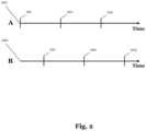
- taking temperature measurements at multiple points in time provides a more holistic view on the cooling scenario. For instance, the door to a cooling room may be closed at time point A and opened at time point B. Only considering temperature measurements for point A or only considering temperature measurements for point B would distort the quantification of the actual cooling scenario.
- taking into account temperature measurements at point A where the door is closed and at point B where the door is opened may provide the advantage of delivering a more accurate description of the cooling scenario.
- the predetermined cooling intensity value is within a range of 1,5 Kelvin Hours and 0,5 Kelvin Hours, and is preferably 1,0 Kelvin Hours.
- Kelvin Hours are a physical unit for quantifying cooling intensity. Thus, indicating the measured cooling intensity in Kelvin Hours may provide compatibility with other methods or systems that use the respective unit. Moreover, Kelvin Hours may ease the understanding of the cooling intensity by personnel. In addition, the mentioned ranges (i.e., between 1,5 Kelvin Hours and 0,5 Kelvin Hours and preferably 1 Kelvin Hours) may provide the advantage of delivering suitable results for evaluating cooling intensity for industrial applications.
- the temperature sensor is preferably arranged at a distance to the cooling device of about 0 to 2 meters, more preferably of about 0,5 and 1,5 meters, and most preferred of about 1 meter of the cooling device.
- arranging the temperature sensor in the vicinity of the cooling device may provide the advantage of delivering accurate temperature readings.
- a distance of about 1 meter may provide most accuracy since it is not arranged too far into the room but also not arranged too close to the cooling device.
- a distance of about 0,5 to 1,5 meters may also provide similar advantages.
- a distance of about 0 to 2 meters may also provide similar advantages. If the temperature sensor were arranged further into the cooling area, the measured temperature value may not record the effect of the cooling device accurately.
- a range between 0 and 2 meters provides some flexibility in positioning the temperature sensor as it is not always possible to place the sensor close to the cooling device due to the structure of the area or room to be cooled.
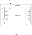
- cooling device A 140 is located in close proximity to the door 101 of the cold storage facility. This means that the temperature that is measured by the temperature sensor 141 of cooling device A 140 shows a higher temperature due to the influx of warm air whenever the door 101 is opened.
- the temperature measurements from the temperature sensor 141 of cooling device A 140 might for example be -20,5°C measured at time X and -20°C measured at time X + 1.
- cooling device B 150 is located on the other side of the cold storage facility where the opening and closing of the door 101 does not significantly influence the measured temperature.
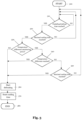
- Fig. 3 shows a flow chart of a method for determining whether to initiate a defrosting process of the cooling device that is usable in industrial environments. It is to note that the sequence of the steps as shown in Fig. 3 is merely an example and that all steps might be executed in a different order or may even be omitted. More specifically, determining that the defrosting process is to be initiated comprises on or more of the steps comprised in the flow chart.
- the first step 310 that is shown in the flow charts checks whether a specific point in time is reached (i.e., a vertical line as shown in Fig. 2 ). If the defrost time has not been reached yet (e.g., the current time is somewhere between two vertical lines in Fig. 2 ), the check is performed again as indicated by a loop in Fig. 3 . If, however, the check is positive and a defrost time is reached, the second step 320 is performed.
- the defrosting step 360 can be reached through different paths and is not limited to the paths specifically mentioned in this description.
- the defrosting step itself comprises the operation of defrosting the cooling device.
- the reset timer step 370 comprises resetting the time that the cooling device has actively been cooling. This value is relevant for the calculation of the minimum duration and the calculation of the maximum duration.
- the process concludes with END 380.
- the flow chart of Fig. 3 demonstrates the flexible method of the present embodiment which automatically adjusts the number of defrost procedures depending on true working conditions (moist air infiltration, ambient temperature, seasonal changes, product load, etc.). It also become obvious that the present embodiment covers all benefits of the conventional methods such as the fixed time schedule method.
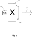
- Fig. 4 shows an exemplary illustration of a cooling device 400.
- Fig. 4 shows an air cooler that is typically used in combination with a plurality of air coolers in an industrial set-up.
- a typical use case is described in more detail in Fig. 1 and includes for example the cooling of a warehouse by a plurality of air coolers. It is to note that the present embodiment is not limited to an air cooler but could be directed to any type of cooling device 400.
- a temperature sensor 410 that is arranged in the vicinity of the cooling device is shown on the left-hand side of the cooling device. As described in detail in Fig. 3 , the temperature sensor 410 measures the local temperature at different points in time to calculate an integral value and determine the cooling intensity of the cooling device.
- Fig. 4 shows that the air cooler comprises a main body 420 through which the air is circulated by means of a fan (not shown) and an exit 430 that emits the air towards the right-hand side of the cooling device 400 as indicated by the arrow 440.
- the circulated air may be passed over a heat exchanger arrangement which may be in thermal connection with an evaporator in which a refrigerant agent may boil and extract the heat from the circulated air flow.
- the air cooler comprises a cooling unit that is configured to execute a computer-implemented method for determining whether to initiate a defrosting process of the cooling device.
- One advantageous of the present embodiment related to a method for determining whether to initiate a defrosting process beside substantial energy consumption reduction may be that the lifetime of the cooling device 400 is increased due to a likely decrease in defrosting cycles.
- the decreased number of defrosting cycles that may arise may also lead to less commissioning and less maintenance requirements compared to conventional methods that for example used a fixed schedule.
- safety measurements that are already implemented to protect from overweight due to excessive ice formation may also be applicable to the present invention.
- a general advantage of the current invention may be its reliability and simplicity from the perspective of the user or a service worker.
- Fig. 5 illustrates a processing system 500 for executing instruction to perform the method for determining whether to initiate a defrosting process of a cooling device usable in an industrial environment.
- the processing system 500 comprises a storage subsystem 501, one or more processors 502, a network interface 503 and a user interface and output device 505.
- the components of the processing system may be connected via a central bus system 506 illustrates at the arrow in Fig. 4 .
- the bus system 506 may be responsible for providing a secure and reliable manner through which the different components of the processing system may communicate.
- the storage subsystem 501 may store computer program code that when executed performs the method for determining whether to initiate the defrosting process.
- the one or more central processing units 502 may be responsible for executing the program code.
- the user interface and output device 505 may be used to adapt predetermined values such as the value of the minimal duration that a cooling device is actively cooling or the value of the maximum duration that a cooling device is actively cooling.
- the processing system 500 may be sued to implement a control unit for controlling a cooling device.
- Embodiments of the present disclosure may be realized in any of various forms, e.g., in software.
- the present invention may be realized as a computer-implemented method, a computer-readable memory medium, or a computer system.
- a non-transitory computer-readable memory medium may be configured so that it stores program instructions and/or data, where the program instructions, if executed by a computer system, cause the computer system to perform a method, e.g., any of the method embodiments described herein, or, any combination of the method embodiments described herein, or, any subset of any of the method embodiments described herein, or, any combination of such subsets.
- a computing device may be configured to include a processor (or a set of processors) and a memory medium, where the memory medium stores program instructions, where the processor is configured to read and execute the program instructions from the memory medium, where the program instructions are executable to implement any of the various method embodiments described herein (or, any combination of the method embodiments described herein, or, any subset of any of the method embodiments described herein, or, any combination of such subsets).
- the device may be realized in any of various forms.
Landscapes
- Engineering & Computer Science (AREA)
- Chemical & Material Sciences (AREA)
- Combustion & Propulsion (AREA)
- Physics & Mathematics (AREA)
- Mechanical Engineering (AREA)
- Thermal Sciences (AREA)
- General Engineering & Computer Science (AREA)
- Defrosting Systems (AREA)
Priority Applications (2)
| Application Number | Priority Date | Filing Date | Title |
|---|---|---|---|
| EP23220434.7A EP4579157A1 (de) | 2023-12-28 | 2023-12-28 | Verfahren, computerprogramm und steuereinheit zur bestimmung, ob ein abtauvorgang einer kühlvorrichtung eingeleitet werden soll |
| PCT/EP2024/083556 WO2025140815A1 (en) | 2023-12-28 | 2024-11-26 | Method, computer program and control unit for determining whether to initiate a defrosting process of a cooling device |
Applications Claiming Priority (1)
| Application Number | Priority Date | Filing Date | Title |
|---|---|---|---|
| EP23220434.7A EP4579157A1 (de) | 2023-12-28 | 2023-12-28 | Verfahren, computerprogramm und steuereinheit zur bestimmung, ob ein abtauvorgang einer kühlvorrichtung eingeleitet werden soll |
Publications (1)
| Publication Number | Publication Date |
|---|---|
| EP4579157A1 true EP4579157A1 (de) | 2025-07-02 |
Family
ID=89474315
Family Applications (1)
| Application Number | Title | Priority Date | Filing Date |
|---|---|---|---|
| EP23220434.7A Pending EP4579157A1 (de) | 2023-12-28 | 2023-12-28 | Verfahren, computerprogramm und steuereinheit zur bestimmung, ob ein abtauvorgang einer kühlvorrichtung eingeleitet werden soll |
Country Status (2)
| Country | Link |
|---|---|
| EP (1) | EP4579157A1 (de) |
| WO (1) | WO2025140815A1 (de) |
Citations (4)
| Publication number | Priority date | Publication date | Assignee | Title |
|---|---|---|---|---|
| EP2426443A2 (de) * | 2010-09-02 | 2012-03-07 | Samsung Electronics Co., Ltd. | Kühlsystem und Abtausteuerungsverfahren dafür |
| KR20170132939A (ko) * | 2016-05-24 | 2017-12-05 | 주식회사 대유위니아 | 냉장고 제상 운전 방법 |
| WO2020230178A1 (en) * | 2019-05-14 | 2020-11-19 | Eliwell Controls S.R.L. Con Unico Socio | Defrost control method in a refrigeration installation and associated control device |
| EP4148355A1 (de) * | 2020-05-07 | 2023-03-15 | Lg Electronics Inc. | Kühlschrank |
-
2023
- 2023-12-28 EP EP23220434.7A patent/EP4579157A1/de active Pending
-
2024
- 2024-11-26 WO PCT/EP2024/083556 patent/WO2025140815A1/en active Pending
Patent Citations (4)
| Publication number | Priority date | Publication date | Assignee | Title |
|---|---|---|---|---|
| EP2426443A2 (de) * | 2010-09-02 | 2012-03-07 | Samsung Electronics Co., Ltd. | Kühlsystem und Abtausteuerungsverfahren dafür |
| KR20170132939A (ko) * | 2016-05-24 | 2017-12-05 | 주식회사 대유위니아 | 냉장고 제상 운전 방법 |
| WO2020230178A1 (en) * | 2019-05-14 | 2020-11-19 | Eliwell Controls S.R.L. Con Unico Socio | Defrost control method in a refrigeration installation and associated control device |
| EP4148355A1 (de) * | 2020-05-07 | 2023-03-15 | Lg Electronics Inc. | Kühlschrank |
Also Published As
| Publication number | Publication date |
|---|---|
| WO2025140815A1 (en) | 2025-07-03 |
Similar Documents
| Publication | Publication Date | Title |
|---|---|---|
| AU2022201272B2 (en) | Maintenance and diagnostics for refrigeration systems | |
| US20180340719A1 (en) | Detection of lack of refrigerant in a cooling system having multiple cooling locations | |
| US20200018537A1 (en) | Digital smart real showcase warning system, method, and program | |
| US20200217535A1 (en) | Digital smart real showcase control system, method, and program | |
| JP5362692B2 (ja) | 冷蔵庫の冷却性能劣化診断システムおよび冷蔵庫の冷却性能劣化診断方法 | |
| EP4579157A1 (de) | Verfahren, computerprogramm und steuereinheit zur bestimmung, ob ein abtauvorgang einer kühlvorrichtung eingeleitet werden soll | |
| US20250146743A1 (en) | A method for generating early temperature warning in a vapour compression system | |
| CN116086844A (zh) | 能效评估方法、装置、系统、设备及存储介质 | |
| JP6587131B2 (ja) | 冷凍システム | |
| JP2011257073A (ja) | エネルギー管理装置 | |
| JP2017053587A (ja) | 冷凍システム | |
| EP3620729B1 (de) | Thermische überwachung für kühlsysteme | |
| JP6610998B2 (ja) | 冷凍システム | |
| TWI722617B (zh) | 非侵入式冷媒洩漏偵測系統、其方法以及其門檻值自適化之方法 | |
| JP2025122776A (ja) | 冷却装置の劣化診断システム | |
| KR20190019762A (ko) | 디프 프리저의 작동이상을 예측하여 감지하는 장치 | |
| Miller et al. | Technical issues with refrigerators | |
| CN120970063A (zh) | 热泵热水器传感温度判断校准方法和装置、设备及介质 | |
| JP2026035100A (ja) | 冷媒の漏えい検知システム | |
| CN115682527A (zh) | 冰箱及其化霜控制方法、可读存储介质 | |
| Miller et al. | Thermal Analysis of Refrigeration Systems Used for Vaccine Storage |
Legal Events
| Date | Code | Title | Description |
|---|---|---|---|
| PUAI | Public reference made under article 153(3) epc to a published international application that has entered the european phase |
Free format text: ORIGINAL CODE: 0009012 |
|
| STAA | Information on the status of an ep patent application or granted ep patent |
Free format text: STATUS: REQUEST FOR EXAMINATION WAS MADE |
|
| 17P | Request for examination filed |
Effective date: 20231228 |
|
| AK | Designated contracting states |
Kind code of ref document: A1 Designated state(s): AL AT BE BG CH CY CZ DE DK EE ES FI FR GB GR HR HU IE IS IT LI LT LU LV MC ME MK MT NL NO PL PT RO RS SE SI SK SM TR |