EP4579169A1 - Vorrichtung zur rückgewinnung von hülsen und waffe mit einer solchen vorrichtung - Google Patents
Vorrichtung zur rückgewinnung von hülsen und waffe mit einer solchen vorrichtung Download PDFInfo
- Publication number
- EP4579169A1 EP4579169A1 EP24222133.1A EP24222133A EP4579169A1 EP 4579169 A1 EP4579169 A1 EP 4579169A1 EP 24222133 A EP24222133 A EP 24222133A EP 4579169 A1 EP4579169 A1 EP 4579169A1
- Authority
- EP
- European Patent Office
- Prior art keywords
- lever
- breech
- rotation
- actuating member
- arm
- Prior art date
- Legal status (The legal status is an assumption and is not a legal conclusion. Google has not performed a legal analysis and makes no representation as to the accuracy of the status listed.)
- Pending
Links
Images


Classifications
-
- F—MECHANICAL ENGINEERING; LIGHTING; HEATING; WEAPONS; BLASTING
- F41—WEAPONS
- F41A—FUNCTIONAL FEATURES OR DETAILS COMMON TO BOTH SMALLARMS AND ORDNANCE, e.g. CANNONS; MOUNTINGS FOR SMALLARMS OR ORDNANCE
- F41A9/00—Feeding or loading of ammunition; Magazines; Guiding means for the extracting of cartridges
- F41A9/60—Empty-cartridge-case or belt-link collectors or catchers
-
- F—MECHANICAL ENGINEERING; LIGHTING; HEATING; WEAPONS; BLASTING
- F41—WEAPONS
- F41A—FUNCTIONAL FEATURES OR DETAILS COMMON TO BOTH SMALLARMS AND ORDNANCE, e.g. CANNONS; MOUNTINGS FOR SMALLARMS OR ORDNANCE
- F41A23/00—Gun mountings, e.g. on vehicles; Disposition of guns on vehicles
- F41A23/34—Gun mountings, e.g. on vehicles; Disposition of guns on vehicles on wheeled or endless-track vehicles
-
- F—MECHANICAL ENGINEERING; LIGHTING; HEATING; WEAPONS; BLASTING
- F41—WEAPONS
- F41A—FUNCTIONAL FEATURES OR DETAILS COMMON TO BOTH SMALLARMS AND ORDNANCE, e.g. CANNONS; MOUNTINGS FOR SMALLARMS OR ORDNANCE
- F41A23/00—Gun mountings, e.g. on vehicles; Disposition of guns on vehicles
- F41A23/28—Wheeled-gun mountings; Endless-track gun mountings
-
- F—MECHANICAL ENGINEERING; LIGHTING; HEATING; WEAPONS; BLASTING
- F41—WEAPONS
- F41A—FUNCTIONAL FEATURES OR DETAILS COMMON TO BOTH SMALLARMS AND ORDNANCE, e.g. CANNONS; MOUNTINGS FOR SMALLARMS OR ORDNANCE
- F41A25/00—Gun mountings permitting recoil or return to battery, e.g. gun cradles; Barrel buffers or brakes
- F41A25/10—Spring-operated systems
Definitions
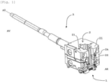
- the technical field of the invention is that of devices for recovering bases, in particular devices for recovering large-calibre ammunition bases for weapons comprising a sleeve breech system and a breech wedge which can slide relative to the sleeve, in particular for tank weapons.
- the recovery device according to the present invention is not limited to the recovery of pellets, but could also be used for the recovery of any non-combustible part of the ammunition such as a case.
- pellet recovery device disclosed in the French patent FR2613235
- This device includes a reinforced canvas collection bag that is placed at the rear of the breech sleeve. The bag must be manually released after firing and recovery of the base, to allow the introduction of new ammunition into the weapon, then also manually replaced before firing.
- this device requires human intervention and the steps of manually placing and manually removing the collection bag are time-consuming. Therefore, such a device is not suitable when the turret is equipped with automatic loading means and a high rate of fire is desired.
- the US patent US8555767 proposes an ammunition butt recovery device that operates automatically, without any human intervention.
- This device comprises a butt recovery bag carried by two movable upper arms and two movable lower arms, such that the bag is placed in a deployed state or in an undeployed state by the movement of the breech sleeve. When the bag is in its undeployed state, the device is retracted under the weapon.
- the present invention thus aims to propose a solution making it possible to maintain high rates of fire by rapid deployment and disengagement of the base recovery device in masked time during firing, and therefore allowing the recovery of ammunition bases fired in a weapon fed using an automatic loading device allowing a very short time interval between two successive shots.
- Another aim of the present invention is to provide a recovery device operating automatically and adjustable in relation to the firing sequence of the weapon, without any human intervention.
- Yet another aim of the present invention is to propose a solution that is less bulky than the solutions of the prior art, and therefore limits the size necessary for the deployment and disengagement of the device.
- the present invention aims to propose a solution that is less bulky than the solutions of the prior art, and therefore limits the size necessary for the deployment and disengagement of the device.
- the present invention aims to propose a solution that is less bulky than the solutions of the prior art, and therefore limits the size necessary for the deployment and disengagement of the device.
- expensive, the recovery device does not require the addition of an actuator.
- Such a device allows automatic recovery of the bases and in masked time during firing. Therefore, thanks to such a device, no human intervention is necessary for the recovery of the bases and the rate of fire is not reduced, the weapon being able to be reloaded as soon as it returns to battery.
- the device being configured to be indexed, on the one hand on the movement of the breech wedge, and on the other hand, on the movement of the breech sleeve, no additional actuator is necessary, thus making it possible to obtain a low-cost device.
- the recovery device comprises a single lever, a distal end of which is secured to the second arm and a proximal end of which is connected to the axis of pivot, the lever and the second arm being perpendicular to each other.
- Such a single-lever kinematics is space-saving.
- the second drive member may include a locking hook arranged to engage the at least one lever when the at least one lever is in its stowed position.
- This locking hook ensures that at least one lever is kept in the folded position and therefore, the maintaining the deployable structure in the undeployed state when the weapon is ready for loading.
- the deployable structure comprises an envelope made of flexible material in the form of a bag, the opening for receiving bases being the only opening of the bag.
- the flexible material casing 42 with a single opening 42a could be replaced by a chute having an upper opening formed by the base receiving opening and a lower opening oriented towards a base storage system.
- the chute recovers the bases with a view to diverting them to a remote storage system.
- the lever 5 In the folded position ( Figures 1 has 3 And 7 ), the lever 5 is arranged against the rear face 2A of the breech sleeve 2, substantially vertically and the second arm 41 extends below the opening of the ejection hole 20, in other words the deployable structure 4 is in the non-deployed state.
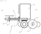
- the lever 5 In the unfolded position ( Figure 4 ), the lever 5 extends away from the rear face 2A of the breech sleeve 2 and rear AR relative to the latter in a plane here forming an angle greater than 90 degrees relative to a vertical plane, and the second arm 41 extends above the opening of the ejection hole 20, in other words the deployable structure 4 is in the deployed state.
- the lever 5 has a longitudinal groove 52 opening on its face directed towards the breech sleeve 2 in the folded position.
- the end region of the groove 52 on the pivot axis 50 side is crossed by a lug 53 parallel to the pivot axis 50.
- the end region of the groove 52 on the second arm 41 side is crossed by a pin 54 mounted to slide along the groove 52.
- the pin 54 is oriented perpendicular to the longitudinal axis of the lever 5 and parallel to the axis of the second arm 41, and is guided by its two ends each extending in a longitudinal notch 55 formed in a respective lateral wall of the lever 5.
- Each end of the pin 54 is connected to one end of an extension spring 56 extending parallel to the longitudinal direction of the lever 5 and the other end of which is connected to an axis secured to the lever 5, mounted closer to the lug 53 than the pin 54.
- the springs 56 therefore stress elastically pins 54 in the direction towards lug 53.
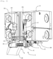
- the displacement mechanism 6, 7, 8 comprises an actuating member 6, a drive assembly 7 and a clutch assembly 8.
- the actuating member 6 has the function of transforming the downward movement of the breech wedge 22 from its closed position to its open position into a rotational movement of the lever 5 from its folded position to its unfolded position by means of the drive assembly 7.
- the actuating member 6 is connected to the breech wedge 22, in particular to the system 9 which manages the downward movement of the breech wedge 22.
- the control system 9 for the movement of the breech wedge 22, in particular its descent comprises a rack 90 extending in a direction parallel to the longitudinal axis A0 of the weapon 3 and carried in the lower part of the breech sleeve 2 so as to be able to slide relative to a bearing 91 secured to the breech sleeve 2.
- a compression spring 92 is mounted around the rack 90 and is interposed between the bearing 91 and a stop 93 secured to the rack 90.
- the rack 90 also meshes with a first pinion 94 which itself meshes with a second pinion 95.
- the front end AV of the rack 90 comes to bear against an obstacle or cam (not shown), carried by the carriage of the weapon 3, which moves the rack 90 towards the rear AR relative to the breech sleeve 2, compressing the compression spring 91.
- the rack 90 then pivots a lever which is, in a known manner, pivotally mounted around a pivot axis, for example here integral in rotation with the first pinion 94, and with one end of the lever which cooperates with a cam path formed in the breech wedge 22, such that the pivoting of the lever leads to a downward movement of the breech wedge 2 to its open position where it will be maintained.
- the actuating member 6 is a tubular part which is mounted around a rotary cylinder 60 carried by the breech sleeve 2 and the rotation of which is controlled by the control system 9 which manages the movement of the breech wedge 22, the connection between the tubular part and the rotary cylinder 60 being a sliding connection.
- Rims 6b projecting towards the inside of said tubular part, at the end of said tubular part on the clutch assembly 8 side, make it possible to form a stop for the positioning of the rotary cylinder 60 in said tubular part, the rotary cylinder 60 bearing against these rims 6b in the coupling position of the clutch assembly 8, as will be described in more detail below.
- the tubular part of the actuating member 6 is a part formed from a single piece and comprising first 61, second 62 and third 63 connecting parts.
- the third connecting portion 63 is a third tubular section of the same outer diameter as the first tubular section and juxtaposed with the second tubular section.
- the second tubular section is arranged between the first and third tubular sections.
- the outer diameter of this third tubular section is dimensioned such that the third connecting portion 63 is adapted to be received in a corresponding tubular section of the drive assembly 7 so as to be able to pivot relative thereto and also to slide towards or away from it.
- the drive assembly 7 has the function of transmitting the rotational movement of the organ actuating member 6 to the lever 5 when the drive assembly 7 is rotatably coupled to the actuating member 6, in order to move the lever 5 from its folded position to its unfolded position.
- the drive assembly 7 also has the function of returning the lever 5 to its folded position when the drive assembly 7 is no longer rotatably coupled to the actuating member 6.
- the first drive element 71 is mounted around the rotary cylinder 60 and around the third connecting part 63.
- the first drive element 71 is mounted to be movable in rotation around the longitudinal axis A1 of the rotary cylinder 60, in the plane containing the lever 5, in other words in vertical alignment with the pivot axis 50.
- the first drive element 71 has a tubular body from the periphery of which two pairs of legs 71a, 71b extend radially.
- the two pairs of legs 71a, 71b are diametrically opposed and each have an axis passing through them.
- the second drive element 72 is mounted to rotate about the axis carried by the first pair of legs 71a.
- the return means 73 is connected to the so-called drive axis 71c, carried by the second pair of legs 71b, which drive axis 71c projects out of the leg 71b on the actuating member 6 side.
- the diameter of the drive axis 71c corresponds to the diameter of the through hole 62b, and the legs 71b and the leg 62a are dimensioned so that the through hole 62b can be aligned with the drive shaft 71c and, if necessary, engaged thereon to secure in rotation the first drive element 71 and the actuating member 6, as will be explained below.
- the tubular body of the first drive element 71 has an internal diameter dimensioned so as to be able to receive the third connecting part 63 while allowing translational movement of the third connecting part 63 along the notched rotating cylinder 60 and inside the tubular body.
- the second drive element 72 is connected to the first drive element 71, to the return means 73 and to the lever 5. As can be seen in the Figures 4 And 7 , it is in the form of a connecting rod having a first low end 72a and a second high end 72b.
- the connecting rod extends in a vertical plane, orthogonal to the pivot axis 50 and to the first 40 and second 41 arms.
- the first end 72a of the connecting rod has a hole for the passage of the axis carried by the first pair of legs 71a of the first drive element 71.
- the connecting rod is rotatably mounted relative to the first drive element 71 at its first end 72a.
- the lower end region of the connecting rod has an arcuate shape to allow the connecting rod to move around the first drive member 71.
- the second end 72b of the connecting rod has an oblong hole 74 through which the lug 53 of the lever 5 extends, which oblong hole 74 is sized to allow the lug 53 to slide therealong.
- the connecting rod has a locking hook 75 directed away from the breech sleeve 2. This locking hook 75 is configured to be engaged by the pin 54 of the lever 5, under the action of the springs 56, when the lever 5 is in the folded position, in order to ensure that the device 1 is clear of the opening of the ejection hole 20.
- the connecting rod has a hole 76 for connecting the return means 73 to the connecting rod.
- the thickness of the connecting rod is chosen such that the connecting rod is capable of being received in the longitudinal groove 52 of the lever 5.
- the return means 73 is a spring whose two ends are respectively connected to the first drive element 71 and to the connecting rod 72.
- This spring 73 is an extension spring having the function of bringing the lugs 71b of the first drive element 71 closer to the connecting rod 72.
- the return means 73 could be connected to the connecting rod 72 and to the cylinder head sleeve 2.
- the clutch assembly 8 has the function of decoupling the actuating member 6 and the drive assembly 7 when the weapon 3 reaches the return-to-battery position, such that the movement of the drive assembly 7 and therefore of the lever 5 is no longer linked to the closing movement of the breech block 22.
- the clutch assembly 8 also has the function of coupling the actuating member 6 and the drive assembly 7 at least during the return-to-battery, such that the movement of the drive assembly 7 and therefore of the lever 5 is again linked to the opening movement of the breech block 22.
- the clutch assembly 8 comprises a thrust element 80, a coupling element 81 and an intermediate element 82.
- the thrust element 80 is connected on the one hand to the cylinder head sleeve 2 and on the other hand to the intermediate element 82. It is in the form of a cylindrical rod supported by two supports 83 spaced from each other and secured to the sleeve 2, in particular by screwing. These two supports 83 each have a through hole for the passage of the rod. The rod is sized such that it is able to slide in the through holes.
- the longitudinal axis A2 of the rod is orthogonal to the pivot axis 50 and to the first 40 and second 41 arms.
- the sliding direction of the rod called thrust direction A2 is orthogonal to the longitudinal axis of the two arms 40, 41.
- the two supports 83 are arranged opposite each other at the base of the breech sleeve 2, on the side of the cheek 21 carrying the pivot axis 50.
- the two supports 83 and therefore the thrust element 80 are positioned below the lower face 2B of the breech sleeve 2.
- the region of the rod which extends beyond the support 83 on the front side AV of the sleeve 2 comprises a fin 80a extending in a corresponding groove formed in the lower face 2B of the breech sleeve 2, the fin 80a projecting on the front side AV of the breech sleeve 2.
- a return spring 84 in particular a compression spring, is mounted around the rod between the two supports 83 so as to tend to move the thrust element 80 forwards AV.
- one end of the spring 84 bears against a shoulder 80b of the rod which is located between the two supports 83 and the other end bears against the support 83 on the rear side AR of the sleeve 2.
- the end region of the rod opposite the region carrying the fin 80a comprises a drive finger 80c.
- the drive finger 80c extends vertically through an orifice made in the end region of the rod, namely orthogonally to the thrust direction A2 and to the first 40 and second 41 arms.
- the coupling element 81 is connected on the one hand to the intermediate element 82 and on the other hand to the actuating member 6.
- the coupling element 81 comprises a part 81a for connection to the actuating member 6 and a part 81b for connection to the intermediate element 82.
- the connecting part 81a is a tubular body mounted to rotate freely around the connecting part 81b and mounted coaxially with the rotating cylinder 60.
- the coupling element 81 is mounted to move in translation along an axis coaxial with the rotating cylinder 60.
- the tubular body is made integral, by screwing, with the first connecting part 61 which is received in said tubular body.
- the connecting part 81b comprises a disc and a tab.
- the disc is housed in the tubular body of the connecting part 81a and is taken between the first connecting part 61 and an inwardly directed rim formed at the end of the connecting part 81a.
- the tab is carried by the disc, perpendicular to the plane of the disc, and therefore projects relative to the connecting part 81a opposite the actuating member 6.
- the tab extends in a horizontal plane and is crossed by a follower finger 81c.
- the follower finger 81c extends vertically, parallel to the drive finger 80c and orthogonally to the translation axis of the coupling element 81.
- the intermediate element 82 is connected on the one hand to the drive finger 80c of the thrust element 80 and on the other hand to the follower finger 81c of the coupling element 81. It comprises a central tube 82a having a longitudinal axis A3 vertical and orthogonal to the thrust direction A2.
- Two pairs of legs 82b extend radially from the central tube 82a.
- the two pairs of legs 82b form an angle of between 90 and 180 degrees between them.
- the two pairs 82b are vertically offset from each other, in other words the two pairs 82b do not extend in the same horizontal plane.
- Each of the legs 82b has a hole oblong 82c, the oblong holes 82c of two legs 82b of the same pair being in vertical alignment with each other.
- One of the pairs of legs 82b is crossed by the follower finger 81c which is able to slide along the oblong holes 82c.
- the other pair of legs 82b is crossed by the drive finger 80c which is able to slide along the oblong holes 82c, the end region of the thrust element 80 comprising the drive finger 80c being received in the space between the two legs 82b.
- a translational movement of the thrust element 80 along the thrust direction A2 towards the coupling element 81 causes the intermediate element 82 to rotate around the fingers 80c, 81c and to move along them, which causes a translational movement of the coupling element 81, and therefore of the actuating member 6, away from the drive assembly 7, until the tab 62a is disengaged from the drive shaft 71c, the actuating member 6 then no longer being rotationally integral with the first drive element 71 and the thrust element 80 then having been moved in translation to a decoupling position.
- a translational movement of the thrust element 80 in the thrust direction A2 opposite the coupling element 81 causes the intermediate element 82 to rotate around the fingers 80c, 81c and to move along them, which causes a translational movement of the coupling element 81, and therefore of the actuating member 6, towards the drive assembly 7, until the through hole 62b of the tab 62a of the actuating member 6 is engaged on the drive axis 71c, thus securing in rotation the actuating member 6 and the first drive element 71, the thrust element 80 having then been moved to a coupling position.
- This translational movement of the thrust element 80 can be obtained by the action of the spring 84 when no more support is exerted on the fin 80a.
- the operation of the pellet recovery device 1 according to the invention is as follows.
- the lever 5 When firing a round and recoiling the breech sleeve 2, the lever 5 is in the folded position, and therefore the deployable structure 4 is in the non-deployed state.
- the clutch assembly 8 At the end of the recoil, the clutch assembly 8 is held in the coupling position by the action of the spring 84.
- the breech wedge 22 is moved from its closed position to its open position. Together with the movement of the breech wedge 22 to its open position, the control system 9 for the movement of the breech wedge 22 causes the rotary cylinder 60, and thus the actuating member 6, to rotate. Since the actuating member 6 is coupled in rotation to the first drive element 71 by the drive axis 71c, the first drive element 71 is then also driven in rotation about the axis of rotation A1. The first drive element 71 being connected to the connecting rod 72, the connecting rod 72 is in turn moved in a vertical plane and rises while being guided by the sliding of the lug 53 of the lever 5 in the oblong hole 74 of the connecting rod 72.
- the locking hook 75 is disengaged from the pin 54, which releases the lever 5 from its folded position.
- the continuation of the upward movement of the connecting rod 72 then causes the lever 5 to rotate around the pivot axis 50.
- the lever 5 is moved to its unfolded position.
- the deployable structure 4 is also unfolded to its deployed state due to the movement of the second arm 41, and the base-receiving opening 42a is opened until it is opposite the opening of the base ejection hole 20 at the rear AR of the breech sleeve 2.
- the various parts are sized for the deployable structure 4 to be in the deployed state as soon as the breech wedge 22 has been released from the ejection hole 20.
- the deployable structure 4 is then maintained in the deployed state as long as the breech wedge 22 is locked in the open position by a conventional extractor system.
- the base which is ejected at the end of the opening of the breech wedge 22 passes through the base receiving opening 42a and is recovered in the casing 42 of the deployable structure 4.
- the thrust element 80 is moved along the thrust direction A2 towards the rear AR of the sleeve 2, namely towards the actuating member 6, against the spring 84, for example by pressing against a fixed support piece secured to the carriage of the weapon 3.
- This translational movement of the thrust element 80 then moves the coupling element 81 in translation along the axis A1 via the intermediate element 82, opposite the actuating member 6.
- this movement of the clutch assembly 8 towards its decoupling position causes the translational movement of the actuating member 6, secured in translation to the coupling element 81, along the axis A1 and opposite the first drive element 71, until the member actuating member 6 and the first drive element 71 are no longer rotationally coupled by the drive shaft 71c. Consequently, the actuating member 6 is always indexed rotating on the rotating cylinder 60 and therefore to the control of the movement of the breech wedge 22, but the first drive element 71 is no longer linked to the control of the movement of the breech wedge 22 and is therefore free to rotate independently of the angular position of the actuating member 6.
- the biasing of the return spring 73 on the first drive element 71 then makes it possible to pull the connecting rod 72 downwards, which returns the lever 5 to the folded position and therefore the deployable structure 4 to the non-deployed state.
- the return force of the springs 56 engages the pin 54 with the locking hook 75.
- the lever 5 is locked relative to the connecting rod 72.
- the passage to the chamber of the weapon 3 is free and in this way the weapon 3 is ready to be loaded for a new shot as soon as it has been brought back into battery.
- the breech wedge 22 is moved to its closed position by the action of the spring. Controlling this movement of the breech wedge 22 causes the actuating member 6 to rotate so as to return the actuating member 6 to an angular position enabling it to rotate the first drive element 71 after the clutch assembly 8 has moved into the coupling position, namely a position in which the through hole 62b of the lug 62a is aligned with the drive axis 71c.
- the movement of the clutch assembly 8 from the decoupling position to the coupling position is obtained during firing, by the action of the return spring 84 at the start of the recoil movement of the weapon 3 and the breech sleeve 2, recoil which releases the thrust element 80 with respect to said support piece and therefore allows the return spring 84 to move the thrust element 80 in translation towards the front AV of the breech sleeve 2.
- the actuating member 6 is again coupled to the drive assembly 7 and therefore the movement of the lever 5 can again be caused by the control of the descent of the breech wedge 22 towards its open position during the subsequent return to battery.
Landscapes
- Engineering & Computer Science (AREA)
- General Engineering & Computer Science (AREA)
- Toys (AREA)
- Battery Mounting, Suspending (AREA)
- Aiming, Guidance, Guns With A Light Source, Armor, Camouflage, And Targets (AREA)
Applications Claiming Priority (1)
| Application Number | Priority Date | Filing Date | Title |
|---|---|---|---|
| FR2315185A FR3157528B1 (fr) | 2023-12-26 | 2023-12-26 | Dispositif de récupération de culots et arme équipée d’un tel dispositif |
Publications (1)
| Publication Number | Publication Date |
|---|---|
| EP4579169A1 true EP4579169A1 (de) | 2025-07-02 |
Family
ID=91335142
Family Applications (1)
| Application Number | Title | Priority Date | Filing Date |
|---|---|---|---|
| EP24222133.1A Pending EP4579169A1 (de) | 2023-12-26 | 2024-12-20 | Vorrichtung zur rückgewinnung von hülsen und waffe mit einer solchen vorrichtung |
Country Status (4)
| Country | Link |
|---|---|
| US (1) | US20250207878A1 (de) |
| EP (1) | EP4579169A1 (de) |
| KR (1) | KR20250100564A (de) |
| FR (1) | FR3157528B1 (de) |
Families Citing this family (1)
| Publication number | Priority date | Publication date | Assignee | Title |
|---|---|---|---|---|
| FR3157926B1 (fr) * | 2024-01-02 | 2026-01-16 | Nexter Systems | Ensemble de positionnement et de maintien en position d’un projectile dans une civière et dispositif d’aide au chargement comportant un tel ensemble |
Citations (3)
| Publication number | Priority date | Publication date | Assignee | Title |
|---|---|---|---|---|
| FR2613235A1 (fr) | 1987-04-02 | 1988-10-07 | France Etat Armement | Dispositif de recuperation de gaz pour armes |
| FR2714158A1 (fr) * | 1993-12-17 | 1995-06-23 | Giat Ind Sa | Dispositif de récupération d'étuis de munitions. |
| US8555767B2 (en) | 2011-12-27 | 2013-10-15 | Agency For Defense Development | Apparatus for collecting an empty cartridge and cannon having the same |
-
2023
- 2023-12-26 FR FR2315185A patent/FR3157528B1/fr active Active
-
2024
- 2024-12-20 EP EP24222133.1A patent/EP4579169A1/de active Pending
- 2024-12-23 US US18/991,849 patent/US20250207878A1/en active Pending
- 2024-12-24 KR KR1020240195656A patent/KR20250100564A/ko active Pending
Patent Citations (3)
| Publication number | Priority date | Publication date | Assignee | Title |
|---|---|---|---|---|
| FR2613235A1 (fr) | 1987-04-02 | 1988-10-07 | France Etat Armement | Dispositif de recuperation de gaz pour armes |
| FR2714158A1 (fr) * | 1993-12-17 | 1995-06-23 | Giat Ind Sa | Dispositif de récupération d'étuis de munitions. |
| US8555767B2 (en) | 2011-12-27 | 2013-10-15 | Agency For Defense Development | Apparatus for collecting an empty cartridge and cannon having the same |
Also Published As
| Publication number | Publication date |
|---|---|
| FR3157528A1 (fr) | 2025-06-27 |
| KR20250100564A (ko) | 2025-07-03 |
| FR3157528B1 (fr) | 2026-01-02 |
| US20250207878A1 (en) | 2025-06-26 |
Similar Documents
| Publication | Publication Date | Title |
|---|---|---|
| EP4579169A1 (de) | Vorrichtung zur rückgewinnung von hülsen und waffe mit einer solchen vorrichtung | |
| EP2627963B1 (de) | Halbautomatische pistole mit schiebelauf | |
| BE1009142A3 (fr) | Dispositif d'ejection pour arme a feu. | |
| EP1070932B1 (de) | Hilfsvorrichtung zur Ladung einer Kanone mit Schraubverschluss | |
| EP3682183A1 (de) | Maschinengewehr | |
| BE1012500A3 (fr) | Arme a feu avec ejection vers l'avant ou reportee vers l'avant de l'arme. | |
| EP4582764A1 (de) | Anordnung zur positionierung und lagesicherung eines geschosses in einer mulde und ladehilfevorrichtung mit einer solchen anordnung | |
| EP0687882B1 (de) | Munitionszuführmechanismus | |
| EP0571265A1 (de) | Munitionsladesystem zum Laden einer schwenkbaren Patronenlagers | |
| EP3682184A1 (de) | Maschinengewehr | |
| EP0661514B1 (de) | Waffe mit bewegbaren Verschlussstücken | |
| EP4249843B1 (de) | Vorrichtung zum laden eines geschosses in die kammer einer waffe | |
| FR2718837A1 (fr) | Arme à feu automatique multitubes de petit ou moyen calibre du type GATLING, notamment destinée au tir de munitions télescopées. | |
| EP0660067B1 (de) | Vorrichtung zum Ausladen von Munition aus einer in einem Panzerturm angeordneten Rohrwaffe | |
| FR2572507A1 (fr) | Fusil automatique perfectionne a canon basculant ou non | |
| FR2726637A1 (fr) | Dispositif pour refouler une munition dans le tube d'un canon, et pour effectuer l'operation inverse | |
| EP0837297B1 (de) | Vorrichtung zum Laden in ein Rohr und Zurückdrängen ins Magazin von grosskalibriger Munition | |
| EP3477242A1 (de) | Maschinengewehr | |
| EP0664430B1 (de) | Munitionsladevorrichtung für eine in einem Panzerturm angeordnete Rohrwaffe | |
| FR2472166A1 (fr) | Dispositif pour un separateur equipant une arme a feu | |
| EP0571266A1 (de) | Einrichtung zum Laden von Munition in einem schwenkbaren Patronenlager | |
| EP0955513B1 (de) | Automatischer Zuführmechanismus für Treibladungsanzünder in einer Artilleriekanone | |
| EP0098463A1 (de) | Tragbares Abschussrohr mit Rückstossbremse | |
| EP0599683A1 (de) | Verfahren zum Laden von Munition in einem schwenkbaren Patronenlager, und Anordnung zur Anwendung | |
| EP3682185A1 (de) | Maschinengewehr |
Legal Events
| Date | Code | Title | Description |
|---|---|---|---|
| PUAI | Public reference made under article 153(3) epc to a published international application that has entered the european phase |
Free format text: ORIGINAL CODE: 0009012 |
|
| STAA | Information on the status of an ep patent application or granted ep patent |
Free format text: STATUS: THE APPLICATION HAS BEEN PUBLISHED |
|
| AK | Designated contracting states |
Kind code of ref document: A1 Designated state(s): AL AT BE BG CH CY CZ DE DK EE ES FI FR GB GR HR HU IE IS IT LI LT LU LV MC ME MK MT NL NO PL PT RO RS SE SI SK SM TR |
|
| STAA | Information on the status of an ep patent application or granted ep patent |
Free format text: STATUS: REQUEST FOR EXAMINATION WAS MADE |
|
| 17P | Request for examination filed |
Effective date: 20251222 |
|
| GRAP | Despatch of communication of intention to grant a patent |
Free format text: ORIGINAL CODE: EPIDOSNIGR1 |
|
| STAA | Information on the status of an ep patent application or granted ep patent |
Free format text: STATUS: GRANT OF PATENT IS INTENDED |
|
| GRAS | Grant fee paid |
Free format text: ORIGINAL CODE: EPIDOSNIGR3 |
|
| INTG | Intention to grant announced |
Effective date: 20260224 |
|
| RIC1 | Information provided on ipc code assigned before grant |
Ipc: F41A 9/60 20060101AFI20260213BHEP |