EP4579182A1 - Procédé de détermination et de visualisation d'une carte de précision - Google Patents
Procédé de détermination et de visualisation d'une carte de précision Download PDFInfo
- Publication number
- EP4579182A1 EP4579182A1 EP23220886.8A EP23220886A EP4579182A1 EP 4579182 A1 EP4579182 A1 EP 4579182A1 EP 23220886 A EP23220886 A EP 23220886A EP 4579182 A1 EP4579182 A1 EP 4579182A1
- Authority
- EP
- European Patent Office
- Prior art keywords
- ori
- accuracy
- surveying instrument
- point
- control points
- Prior art date
- Legal status (The legal status is an assumption and is not a legal conclusion. Google has not performed a legal analysis and makes no representation as to the accuracy of the status listed.)
- Pending
Links
Images

Classifications
-
- G—PHYSICS
- G01—MEASURING; TESTING
- G01C—MEASURING DISTANCES, LEVELS OR BEARINGS; SURVEYING; NAVIGATION; GYROSCOPIC INSTRUMENTS; PHOTOGRAMMETRY OR VIDEOGRAMMETRY
- G01C15/00—Surveying instruments or accessories not provided for in groups G01C1/00 - G01C13/00
- G01C15/002—Active optical surveying means
Definitions
- the present invention relates to a method for determining in a worksite an accuracy map according to the definition of claim 1, to a computer program according to the definition of claim 6, and to an apparatus according to the definition of claim 6.
- Surveying instruments such as total stations, are used in construction industries to take individual, highly accurate measurements within a worksite, using a highly precise electronic distance measuring device and highly accurate motors to rotate this electronic distance measuring device. Centered within a total station is its coordinate frame. The orientation of the coordinate frame is usually such that the stations x-axis pointing towards right, y-axis pointing towards the floor, and z-axis pointing into forward direction.
- Known workflows to determine the pose (position and orientation) of a total station are based on manually or automatically taking measurement samples of distance and angle data in the worksite. Based on a scalable mathematical equation system, the pose can be calculated with a varying degree of precision, depending on the amount of sampling information considered. To solve the pose calculation, a minimum number of measurement samples needs to be taken, while an increasing number of measurement samples usually leads to the formation of an overdetermined mathematical equation system and an overall improved accuracy of the pose calculation.
- control points are positioned at scattered locations at the worksite to be surveyed.
- control points are materialized by prisms, cat-eyes, reflective foils, or other forms of reflective targets for returning the laser beam from the total station.
- the exact location of each control point is determined and logged in terms of coordinates on a specified coordinate frame, typically the coordinate frame of a floorplan of the worksite.
- a total station can then sight a number of these control points to determine its absolute position on that X, Y, Z coordinate frame using standard triangulation techniques.
- the operator determines the distance and angle data successively for each control point. These data are stored in the total station's computer system together with the absolute position data for the respective control points, the latter position data being preloaded into the total station.
- the total station then implements an algorithm, generally known as a free-stationing algorithm, to determine its pose from the sightings of those control points.
- the positioning accuracy of a total station is inversely proportional to the square root of the number of control points it can exploit from its location, the angular distribution of those control points, as well as the stability of the worksite at which the control points and the total station are deployed.
- the pose and its standard deviation are shown to the operator as numerical values and the interpretation of the quality is left to the operator and depends on his experience.
- Leica has released in November 2022 a new version v7.5 of their iCON Field software and included a functionality that shows to the operator a recommended working area that is a polygon created by the control points used for computing the pose.
- the disadvantage of the known functionality is that the working area is not evaluated based on an accuracy threshold that can be achieved during measuring and/or layouting with the total station.
- a computer-implemented method for determining for a working area at a worksite in which a surveying instrument is deployed at a station, an accuracy map, which shows for the working area at least one accuracy that can be achieved during operating the surveying instrument, the method being performed by a computer system and comprising the steps:
- the method for determining an accuracy map supports the operator of the surveying instrument in understanding the results he achieved during stationing of the surveying instrument.
- the predefined working area is divided in a grid of pixels. That grid of pixels is used to compute the accuracy for at least one representative point of the pixels, the representative point can be a center point or any other point of the pixels.
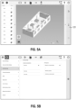
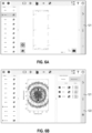
- the accuracy map is computed by the computer system based on the pose, the variances and covariances for the station, and on measuring accuracies. Finally, a graphical representation of the accuracy map is shown on a display.
- the operator is supported by the graphical representation of the accuracy map.
- the values represented by the accuracy map would normally be much harder for the operator to understand if presented numerically in a spreadsheet, especially if the data set is large or complex.
- the accuracy map enables operators to visualize data and understand it easily. The operator can easily check via the graphical representation if he can achieve the required accuracy during layouting or measuring with the surveying instrument at the worksite.
- the accuracy map is related to the worksite and stored in the computer system and/or stored to a memory connected to the computer system and the accuracy map is provided for use in operating the surveying instrument.
- the accuracy map is provided for use in operating the surveying instrument.
- the accuracy map is provided for use in layouting a point of interest and upon selecting the point of interest and defining an accuracy threshold, it is checked by the computer system if the accuracy threshold can be achieved, wherein:
- the pose, and the corresponding variances and covariances are computed by a free-stationing algorithm based on a set of control points having known first coordinates in a first coordinate frame of the worksite and at least a sub-set of the set of control points having known second coordinates in a second coordinate frame of the surveying instrument.
- Free-stationing algorithms are typically used to determine the pose, and corresponding variances and covariances of a surveying instrument in the first coordinate frame of the worksite.
- To compute the pose at least two control points are required, the pose is computed from the first coordinates of the control points in the first coordinate frame and from the second coordinates in the second coordinate frame.
- the quality of the pose is proportional to the number of control points, the angular distribution of those control points, and the stability of the worksite at which the control points and the surveying instrument are deployed.
- the graphical representation of the layout area can support the operator in finding an appropriate selection of control points to determine the pose of the surveying instrument via a free-stationing algorithm.
- second coordinates are determined for the at least one further control point by the surveying instrument in the second coordinate frame, and a new sub-set of control points containing the sub-set of control points and the at least one further control point is defined, the method further comprising:
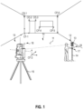
- FIG. 1 shows an operator using a surveying instrument 10 deployed at a worksite 11.
- the worksite 11 may be a construction site, inside or outside, or a surveying site, amongst others.
- a target 12 that is remote from the surveying instrument 10 may be deployed at the worksite 11.
- the target 12 may include a reflector 13, such as a prism and/or a cat-eye, that is mounted on top of a pole 14.
- the surveying instrument 10 is formed as a total station and comprises a measuring unit 15 that is mounted on a mounting support structure in the form of a tripod 16.
- the surveying instrument 10 also comprises a removable control panel in the form of a remote controller 17 that can be used for remote control of the measuring unit 15 via a wireless connection 18.
- the total station 10 Before the operator can use the total station 10 for layouting, measuring and/or other tasks, the total station must be stationed via a stationing process to the worksite 11.
- stationing processes are known, such as free-stationing process, model-based stationing process, automatic stationing process, or any other stationing process.
- control points CP-1, CP-2, CP-3, CP-4, CP-5, CP-6 are positioned at scattered locations at the worksite 11.
- the control points are materialized by prisms, cat-eyes, reflective foils, or other forms of reflective targets for returning the laser beam from the total station.
- the exact location of the control points is determined and logged in terms of coordinates on a specified coordinate frame, here the coordinate frame of the worksite 11.
- the total station 10 To determine the pose (position and orientation) of the total station 10 in the coordinate frame of the worksite 11, the total station 10 sights a number of the control points and takes measurement samples of distance and angle data in its coordinate frame.
- the coordinate frame of the worksite 11 is called “first coordinate frame” CF-1 and the coordinate frame of the total station 10 is called “second coordinate frame” CF-2.
- the coordinates in the first coordinate frame CF-1 are called “first coordinates” and the coordinates in the second coordinate frame CF-2 are called “second coordinates".
- the pose of the total station can be calculated from the first coordinates of the control points in the first coordinate frame CF-1 and from the second coordinates of the control points in the second coordinate frame CF-2.
- the position accuracy of the pose can increase.
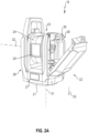
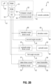
- FIGS. 2A , B show an exemplary version of the measuring unit 15 used in the surveying instrument 10 of FIG. 1 in a perspective view ( FIG. 2A ) and a block diagram of the main components of the measuring unit 15 as illustrated in FIG. 2A ( FIG. 2B ).
- the surveying instrument 10 is designed as robotic total station and the measuring unit 15 comprises a base 21, a support 22, and a measuring head 23.
- the measuring head 23 is enclosed by a housing 24, which includes an exit window 25.
- a distance measuring device that can emit a distance measuring beam and a tracking device that can emit a radiation are arranged. The distance measuring beam and the radiation are emitted through the exit window 25 to leave the housing 24.
- the support 22 is U-formed and includes a bottom portion 27, a first side portion 28, and a second side portion 29.
- the support 22 can rotate completely around its circumference at a full 360° angle with respect to the base 21 about a first axis of rotation 31.
- the measuring head 23 is pivotably mounted to the support 22 about a second axis of rotation 32 and is arranged between the first side portion 28 and the second side portion 29 of the support.
- the first axis of rotation 31 is aligned parallel to a local direction of gravitation 33
- the second axis of rotation 32 is aligned perpendicular to the local direction of gravitation 33.
- An azimuth motor device and a first angle encoder may be located in the bottom portion 27 of the support 22 and allow to rotate the measuring unit 15 about the first axis of rotation 31 and to determine the direction of the distance measuring beam in a first plane perpendicular to the first axis of rotation 31.
- An elevation motor device and a second angle encoder may be located in the first side portion 28 of the support 22 and allow the measuring head 23 to pivot about the second axis of rotation 32 and to determine the direction of the distance measuring beam in a second plane perpendicular to the second axis of rotation 32.
- a self-leveling device which may be arranged in the bottom portion 27 of the support 22, can be included.
- FIG. 2B shows a block diagram of the main components of the measuring unit 15 of the surveying instrument 10.
- the measuring unit 15 includes a first electronic device 41, a distance measuring device 42, a first angle encoder 43, an azimuth motor device 44, a second angle encoder 45, and an elevation motor device 46.
- the measuring unit 15 can additionally include one or more cameras, such as a tracking camera configured to track a reflector target, or an aiming camera configured to let the user aim to a point of interest.
- the first electronic device 41 comprises a first processing circuit ( ⁇ P) 50, a first memory circuit 51 that may include associated random-access memory (RAM) and read only memory (ROM), a first communications circuit 52, and a first input/output (I/O) interface circuit 53.
- the first processing circuit 50 also called device control unit, may communicate with the first memory circuit 51 and first communications circuit 52 and is configured to control the laser instrument 12.
- the first communications circuit 52 includes a first transmitter circuit 54 and a first receiver circuit 55 and is configured to be connected to a communications circuit of the remote controller via the communication link.
- the first input/output interface circuit 53 is an interface between the first processing circuit 50 and the various types of motor driver circuits and sensor circuits of the measuring unit 15.
Landscapes
- Physics & Mathematics (AREA)
- Engineering & Computer Science (AREA)
- General Physics & Mathematics (AREA)
- Radar, Positioning & Navigation (AREA)
- Remote Sensing (AREA)
- Length Measuring Devices With Unspecified Measuring Means (AREA)
Priority Applications (3)
| Application Number | Priority Date | Filing Date | Title |
|---|---|---|---|
| EP23220886.8A EP4579182A1 (fr) | 2023-12-31 | 2023-12-31 | Procédé de détermination et de visualisation d'une carte de précision |
| EP24188392.5A EP4579185A1 (fr) | 2023-12-31 | 2024-07-12 | Procédé de détermination et de visualisation d'une carte de précision |
| PCT/EP2024/087105 WO2025140907A1 (fr) | 2023-12-31 | 2024-12-18 | Procédé de détermination et de visualisation d'une carte de précision |
Applications Claiming Priority (1)
| Application Number | Priority Date | Filing Date | Title |
|---|---|---|---|
| EP23220886.8A EP4579182A1 (fr) | 2023-12-31 | 2023-12-31 | Procédé de détermination et de visualisation d'une carte de précision |
Publications (1)
| Publication Number | Publication Date |
|---|---|
| EP4579182A1 true EP4579182A1 (fr) | 2025-07-02 |
Family
ID=89473404
Family Applications (2)
| Application Number | Title | Priority Date | Filing Date |
|---|---|---|---|
| EP23220886.8A Pending EP4579182A1 (fr) | 2023-12-31 | 2023-12-31 | Procédé de détermination et de visualisation d'une carte de précision |
| EP24188392.5A Pending EP4579185A1 (fr) | 2023-12-31 | 2024-07-12 | Procédé de détermination et de visualisation d'une carte de précision |
Family Applications After (1)
| Application Number | Title | Priority Date | Filing Date |
|---|---|---|---|
| EP24188392.5A Pending EP4579185A1 (fr) | 2023-12-31 | 2024-07-12 | Procédé de détermination et de visualisation d'une carte de précision |
Country Status (1)
| Country | Link |
|---|---|
| EP (2) | EP4579182A1 (fr) |
Cited By (1)
| Publication number | Priority date | Publication date | Assignee | Title |
|---|---|---|---|---|
| WO2026013267A1 (fr) * | 2024-07-12 | 2026-01-15 | Hilti Aktiengesellschaft | Procédé de détermination d'une précision pour un point d'intérêt |
Citations (3)
| Publication number | Priority date | Publication date | Assignee | Title |
|---|---|---|---|---|
| US20100309311A1 (en) * | 2008-02-12 | 2010-12-09 | Trimble Ab | Localization of a surveying instrument in relation to a ground mark |
| US20210055102A1 (en) * | 2019-08-22 | 2021-02-25 | Leica Geosystems Ag | Surveying system with image-based measuring |
| CN112964237A (zh) * | 2021-02-10 | 2021-06-15 | 北京测绘学会 | 针对施工工程的测量控制系统、方法、装置、计算机设备 |
Family Cites Families (2)
| Publication number | Priority date | Publication date | Assignee | Title |
|---|---|---|---|---|
| EP4394319A1 (fr) | 2022-12-31 | 2024-07-03 | Hilti Aktiengesellschaft | Procédé et système de détermination d'une pose pour un instrument laser |
| EP4394320A1 (fr) | 2023-01-01 | 2024-07-03 | Hilti Aktiengesellschaft | Procédé et système de détermination d'une pose pour un instrument laser |
-
2023
- 2023-12-31 EP EP23220886.8A patent/EP4579182A1/fr active Pending
-
2024
- 2024-07-12 EP EP24188392.5A patent/EP4579185A1/fr active Pending
Patent Citations (3)
| Publication number | Priority date | Publication date | Assignee | Title |
|---|---|---|---|---|
| US20100309311A1 (en) * | 2008-02-12 | 2010-12-09 | Trimble Ab | Localization of a surveying instrument in relation to a ground mark |
| US20210055102A1 (en) * | 2019-08-22 | 2021-02-25 | Leica Geosystems Ag | Surveying system with image-based measuring |
| CN112964237A (zh) * | 2021-02-10 | 2021-06-15 | 北京测绘学会 | 针对施工工程的测量控制系统、方法、装置、计算机设备 |
Cited By (1)
| Publication number | Priority date | Publication date | Assignee | Title |
|---|---|---|---|---|
| WO2026013267A1 (fr) * | 2024-07-12 | 2026-01-15 | Hilti Aktiengesellschaft | Procédé de détermination d'une précision pour un point d'intérêt |
Also Published As
| Publication number | Publication date |
|---|---|
| EP4579185A1 (fr) | 2025-07-02 |
Similar Documents
| Publication | Publication Date | Title |
|---|---|---|
| US10586349B2 (en) | Excavator bucket positioning via mobile device | |
| EP2904351B1 (fr) | Systèmes et procédés de mesure de position perfectionnés | |
| US9584768B2 (en) | Information processing apparatus, information processing method and computer-readable storage medium | |
| US20100226541A1 (en) | System and method for detecting position of underwater vehicle | |
| US11461526B2 (en) | System and method of automatic re-localization and automatic alignment of existing non-digital floor plans | |
| CN111932611B (zh) | 物体位置获取方法和装置 | |
| EP3945282B1 (fr) | Système de surveillance, procédé d'assistance au tuteurage et programme d'assistance au tuteurage | |
| EP3479142B1 (fr) | Appareil d'imagerie radiologique | |
| EP4394320A1 (fr) | Procédé et système de détermination d'une pose pour un instrument laser | |
| EP3961151B1 (fr) | Système de surveillance, procédé d'assistance au tuteurage et programme d'assistance au tuteurage | |
| EP3479143B1 (fr) | Radiamètre portable et procédé | |
| EP4579182A1 (fr) | Procédé de détermination et de visualisation d'une carte de précision | |
| CN110161490B (zh) | 具有布局生成功能的距离测量系统 | |
| CN110332854A (zh) | 目标物的定位方法、瞄准镜及计算机可读存储介质 | |
| WO2021174037A1 (fr) | Dispositif d'alignement laser | |
| JP6812114B2 (ja) | 測量位置表示装置及び測量位置表示プログラム | |
| EP4579180A1 (fr) | Procédé de détermination et de visualisation d'une zone de présentation | |
| EP4579181A1 (fr) | Procédé d'optimisation et de visualisation d'une zone de mise en page | |
| EP4679032A1 (fr) | Procédé de détermination d'une précision pour un point d'intérêt | |
| WO2025140907A1 (fr) | Procédé de détermination et de visualisation d'une carte de précision | |
| EP4696981A1 (fr) | Pointeur de disposition motorisé comprenant une unité de mesure de distance et procédé d'indication d'un point de disposition sur un chantier | |
| EP4696978A1 (fr) | Appareil et procédé pour indiquer un point de disposition sur un chantier au moyen d'une station totale | |
| EP4696980A1 (fr) | Pointeur de disposition motorisé et procédé d'indication d'un point de disposition sur un chantier | |
| JP2022066992A (ja) | 測位装置、測位方法、および測位プログラム | |
| EP4394316A1 (fr) | Procédé et système d'évaluation d'une pose pour un instrument laser |
Legal Events
| Date | Code | Title | Description |
|---|---|---|---|
| PUAI | Public reference made under article 153(3) epc to a published international application that has entered the european phase |
Free format text: ORIGINAL CODE: 0009012 |
|
| STAA | Information on the status of an ep patent application or granted ep patent |
Free format text: STATUS: THE APPLICATION HAS BEEN PUBLISHED |
|
| AK | Designated contracting states |
Kind code of ref document: A1 Designated state(s): AL AT BE BG CH CY CZ DE DK EE ES FI FR GB GR HR HU IE IS IT LI LT LU LV MC ME MK MT NL NO PL PT RO RS SE SI SK SM TR |