EP4579276A1 - Système et procédé de mesure d'une distance par rapport à un objet - Google Patents
Système et procédé de mesure d'une distance par rapport à un objet Download PDFInfo
- Publication number
- EP4579276A1 EP4579276A1 EP23220572.4A EP23220572A EP4579276A1 EP 4579276 A1 EP4579276 A1 EP 4579276A1 EP 23220572 A EP23220572 A EP 23220572A EP 4579276 A1 EP4579276 A1 EP 4579276A1
- Authority
- EP
- European Patent Office
- Prior art keywords
- beat frequency
- quadrature
- light
- phase
- radio
- Prior art date
- Legal status (The legal status is an assumption and is not a legal conclusion. Google has not performed a legal analysis and makes no representation as to the accuracy of the status listed.)
- Pending
Links
Images


Classifications
-
- G—PHYSICS
- G01—MEASURING; TESTING
- G01S—RADIO DIRECTION-FINDING; RADIO NAVIGATION; DETERMINING DISTANCE OR VELOCITY BY USE OF RADIO WAVES; LOCATING OR PRESENCE-DETECTING BY USE OF THE REFLECTION OR RERADIATION OF RADIO WAVES; ANALOGOUS ARRANGEMENTS USING OTHER WAVES
- G01S17/00—Systems using the reflection or reradiation of electromagnetic waves other than radio waves, e.g. lidar systems
- G01S17/02—Systems using the reflection of electromagnetic waves other than radio waves
- G01S17/06—Systems determining position data of a target
- G01S17/08—Systems determining position data of a target for measuring distance only
- G01S17/32—Systems determining position data of a target for measuring distance only using transmission of continuous waves, whether amplitude-, frequency-, or phase-modulated, or unmodulated
- G01S17/34—Systems determining position data of a target for measuring distance only using transmission of continuous waves, whether amplitude-, frequency-, or phase-modulated, or unmodulated using transmission of continuous, frequency-modulated waves while heterodyning the received signal, or a signal derived therefrom, with a locally-generated signal related to the contemporaneously transmitted signal
-
- G—PHYSICS
- G01—MEASURING; TESTING
- G01S—RADIO DIRECTION-FINDING; RADIO NAVIGATION; DETERMINING DISTANCE OR VELOCITY BY USE OF RADIO WAVES; LOCATING OR PRESENCE-DETECTING BY USE OF THE REFLECTION OR RERADIATION OF RADIO WAVES; ANALOGOUS ARRANGEMENTS USING OTHER WAVES
- G01S7/00—Details of systems according to groups G01S13/00, G01S15/00, G01S17/00
- G01S7/48—Details of systems according to groups G01S13/00, G01S15/00, G01S17/00 of systems according to group G01S17/00
- G01S7/491—Details of non-pulse systems
- G01S7/4912—Receivers
- G01S7/4915—Time delay measurement, e.g. operational details for pixel components; Phase measurement
-
- G—PHYSICS
- G01—MEASURING; TESTING
- G01S—RADIO DIRECTION-FINDING; RADIO NAVIGATION; DETERMINING DISTANCE OR VELOCITY BY USE OF RADIO WAVES; LOCATING OR PRESENCE-DETECTING BY USE OF THE REFLECTION OR RERADIATION OF RADIO WAVES; ANALOGOUS ARRANGEMENTS USING OTHER WAVES
- G01S17/00—Systems using the reflection or reradiation of electromagnetic waves other than radio waves, e.g. lidar systems
- G01S17/02—Systems using the reflection of electromagnetic waves other than radio waves
- G01S17/50—Systems of measurement based on relative movement of target
- G01S17/58—Velocity or trajectory determination systems; Sense-of-movement determination systems
-
- G—PHYSICS
- G01—MEASURING; TESTING
- G01S—RADIO DIRECTION-FINDING; RADIO NAVIGATION; DETERMINING DISTANCE OR VELOCITY BY USE OF RADIO WAVES; LOCATING OR PRESENCE-DETECTING BY USE OF THE REFLECTION OR RERADIATION OF RADIO WAVES; ANALOGOUS ARRANGEMENTS USING OTHER WAVES
- G01S17/00—Systems using the reflection or reradiation of electromagnetic waves other than radio waves, e.g. lidar systems
- G01S17/88—Lidar systems specially adapted for specific applications
- G01S17/93—Lidar systems specially adapted for specific applications for anti-collision purposes
- G01S17/931—Lidar systems specially adapted for specific applications for anti-collision purposes of land vehicles
-
- G—PHYSICS
- G01—MEASURING; TESTING
- G01S—RADIO DIRECTION-FINDING; RADIO NAVIGATION; DETERMINING DISTANCE OR VELOCITY BY USE OF RADIO WAVES; LOCATING OR PRESENCE-DETECTING BY USE OF THE REFLECTION OR RERADIATION OF RADIO WAVES; ANALOGOUS ARRANGEMENTS USING OTHER WAVES
- G01S7/00—Details of systems according to groups G01S13/00, G01S15/00, G01S17/00
- G01S7/48—Details of systems according to groups G01S13/00, G01S15/00, G01S17/00 of systems according to group G01S17/00
- G01S7/481—Constructional features, e.g. arrangements of optical elements
- G01S7/4816—Constructional features, e.g. arrangements of optical elements of receivers alone
-
- G—PHYSICS
- G01—MEASURING; TESTING
- G01S—RADIO DIRECTION-FINDING; RADIO NAVIGATION; DETERMINING DISTANCE OR VELOCITY BY USE OF RADIO WAVES; LOCATING OR PRESENCE-DETECTING BY USE OF THE REFLECTION OR RERADIATION OF RADIO WAVES; ANALOGOUS ARRANGEMENTS USING OTHER WAVES
- G01S7/00—Details of systems according to groups G01S13/00, G01S15/00, G01S17/00
- G01S7/48—Details of systems according to groups G01S13/00, G01S15/00, G01S17/00 of systems according to group G01S17/00
- G01S7/491—Details of non-pulse systems
- G01S7/4911—Transmitters
-
- G—PHYSICS
- G01—MEASURING; TESTING
- G01S—RADIO DIRECTION-FINDING; RADIO NAVIGATION; DETERMINING DISTANCE OR VELOCITY BY USE OF RADIO WAVES; LOCATING OR PRESENCE-DETECTING BY USE OF THE REFLECTION OR RERADIATION OF RADIO WAVES; ANALOGOUS ARRANGEMENTS USING OTHER WAVES
- G01S7/00—Details of systems according to groups G01S13/00, G01S15/00, G01S17/00
- G01S7/48—Details of systems according to groups G01S13/00, G01S15/00, G01S17/00 of systems according to group G01S17/00
- G01S7/491—Details of non-pulse systems
- G01S7/4912—Receivers
- G01S7/4917—Receivers superposing optical signals in a photodetector, e.g. optical heterodyne detection
Definitions
- US 10,578,738 B2 relates to a chirped laser radar system that is described to be capable of unambiguously detecting the range and the velocity relative to a moving target.
- the system comprises two laser sources having different chirp rates, wherein in one embodiment one of the chirp rates is zero.
- the provision of a second laser significantly increases the system complexity.
- an FMCW LiDAR system for measuring a range to an object comprising a light source configured to produce light having a varying frequency, an optical circuitry configured to emit the light produced by the light source and to receive measuring light that was reflected from the object, and a detector.
- the latter comprises a quadrature optical mixer configured to receive the measuring light and reference light, which was not reflected from the object, and to produce an in-phase radio beat frequency and a quadrature shifted radio beat frequency based on a superposition of the measuring light and the reference light, and a phase-locked loop configured to produce, based on the in-phase radio beat frequency and the quadrature shifted radio beat frequency received from the quadrature mixer, an electrical signal representing an absolute value and a sign of a synthesized beat frequency.
- a computing unit is configured to compute a range to the object based on the electrical signal.
- the invention is based on the perception that it is possible to detect the sign of the beat frequency if the superposition of the measuring light and the reference light is described by a combination of the in-phase radio beat frequency and the quadrature shifted radio beat frequency.
- these two signals represent the real part and the imaginary part of the complex beat frequency and thus bear the information about the sign of the beat frequency which is required to resolve the Doppler ambiguity.
- Using a phase-locked loop it is possible to extract from these two signals a synthesized beat frequency represented by a locked electrical signal that has a sign corresponding to the sign of the beat frequency.
- This beat frequency is referred to as "synthesized” because it has been reconstructed from the in-phase and quadrature shifted components of the "original" beat frequency detected in the quadrature optical mixer.
- the locked electrical signal represents both the absolute value and the sign of the beat frequency, it is possible to compute the range and velocity information unambiguously without a need to compute a Fast Fourier Transform (FFT) for thousands of points in real time.
- FFT Fast Fourier Transform
- the quadrature optical mixer comprises a quadrature hybrid coupler comprising a first input configured to receive the measuring light, a second input configured to receive the reference light, and four exits combining the measuring light and the reference light with different phase delays.
- the quadrature optical mixer further comprises a first pair of photodetectors connected to two of the four exits of the quadrature hybrid coupler and configured to produce the in-phase radio beat frequency, and a second pair of photodetectors connected to the other two of the four exits of the quadrature hybrid coupler and configured to produce the quadrature shifted radio beat frequency.
- the system may comprise a quadrature splitter that is connected to the oscillator and comprises a first exit port connected to the first electrical mixer and a second exit port connected to the second electrical mixer.
- the object outlined above is achieved by a method for measuring a range to an object using an FMCW LiDAR system comprising the following steps:
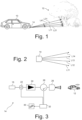
- Figure 1 is a schematic side view showing a vehicle 10 that approaches an object 12 represented by a tree.
- the vehicle 10 has a LiDAR system 14 that scans the environment lying ahead of the vehicle 10 with light beams L11, L21, L31, and L41. From range information associated to each light beam, a three-dimensional image of the environment is computationally reconstructed.
- the LiDAR system 14 determines the relative velocity to the object 12 along the direction of the respective light beam L11, L21, L31, and L41. This information is particularly important if the object 12 is not fixed, but moves, too.
- the information computed by the LiDAR system 14 about the environment lying ahead of the vehicle 10 may be used, for example, to assist the driver of the vehicle 10 in various ways. For example, warning messages may be generated if a collision of the vehicle 10 with the object 12 threatens. If the vehicle 10 drives autonomously, range and velocity information about the environment lying ahead are required by the algorithms that control the vehicle 10.
- the LiDAR system 14 emits the light beams L11 to L41 in different directions in a vertical plane (i.e. the plane of the paper in Figure 1 ) so that the environment is scanned in the vertical direction. Scanning also takes place simultaneously in the horizontal direction, as Figure 2 illustrates in a top view of the LiDAR system 14.
- Four light beams L11, L12, L13 and L14 are emitted in a horizontal plane in different directions.
- FIG 3 schematically shows the layout of the LiDAR system 14.
- the LiDAR system 14 is configured as an FMCW LiDAR system and comprises a light source 16.
- the light source 16 produces light having a frequency f chirp that periodically varies ("chirps") between a lower frequency f l and a higher frequency f h .
- the light source 16 is connected to a splitter 22 that splits the measuring light into reference light (sometimes also referred to as "local oscillator") and measuring light.
- the measuring light passes an optical amplifier 24 and an optical circulator 26 that guides the amplified output light towards a scanning unit 28.
- An optical circulator has three ports A, B and C and has the property that light entering one port leaves the next port. Therefore, light entering port A leaves port B, light entering port B leaves port C, and light entering port C leaves port A.
- the optical circulator 26 may comprise a polarization sensitive beam splitter and a Faraday rotator that is arranged in the optical path upstream the scanning unit 28 so as to rotate the state of polarization by 45°, as this is known in the art as such. This ensures that measuring light from the amplifier 24 passes the beam splitter without being deviated, while the state of polarization of light reflected from the object 12 will undergo a rotation of 2 ⁇ 45° so that it is deviated by the polarization sensitive beam splitter.
- an amplifier 24 that amplifies only the measuring light it is also possible, for example, to amplify the measuring light before it enters the splitter 22, to use at least one amplifier arranged in at least one light path between the light sources 16, 18 and the optical combiner 20, or to dispense with the amplifier 24 completely.
- the optical circulator 26 directs the measuring light towards a detector 32 that will be explained in more detail below. Because of the constantly varying frequency f chirp of the light emitted by the light source 16, the frequencies of the reference light and the measuring light, which has propagated to the object 12 and back to the LiDAR system 10, are slightly different. Consequently, a superposition of the reference light and the measuring light results in an optical beat frequency that is detected by the detector 32.
- the electrical signal produced by the detector 32 is fed to a computing unit 35 that computes the range R to the object and the relative velocity v between the LiDAR system 14 and the object 12 by analyzing the beat frequencies resulting from the superposition detected by the detector 32.
- This analog electrical signal is converted to a digital signal by an analog-to-digital converter (ADC) 48 and then input to a digital signal processor (DSP) 50.
- ADC analog-to-digital converter
- DSP digital signal processor
- the latter is part of the computing unit 35 that computes the range to the object 12 and the relative radial velocity based on the synthesized beat frequency, as this is known in the art as such.
- the quadrature optical mixer 36 is part of a Si-SiN based photonic integrated circuit (PIC) 52, while the phase-locked loop 46 is part of an electronic integrated circuit 54. Both circuits 52, 54 are connected by electrical lines transmitting the in-line and quadrature shifted radio beat frequencies.
- PIC photonic integrated circuit
- the quadrature optical mixer 36 comprises a quadrature hybrid coupler 56, which in this embodiment is formed by a 2 x 4 star coupler comprising the two inputs 38, 40 and four outputs 58 that combine light from the two inputs 38, 40 with phase delays of 0°, 90°, 180° and 270°, respectively.
- the quadrature optical mixer 36 further comprises two first photodetectors 60a, 60b and two second photodetectors 62a, 62b each having an electrical output and being connected to one of the outputs 58 of the quadrature hybrid coupler 56.
- the phase-locked loop 46 comprises in this embodiment a voltage-controlled oscillator (VCO) 70 that is connected to a quadrature splitter 72 converting the oscillations with frequency f b0 produced by the voltage-controlled oscillator 70 into an in-phase (0°) oscillation signal f 0,0° and a quadrature shifted (90°) oscillation signal f 0,90° .
- VCO voltage-controlled oscillator
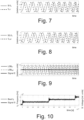
- Sl f b and SQ f b signals that are shown in Figures 7 and 8 as grey solid lines, the two f 0,90° and f 0,90° signals are represented as dashed black lines in Figures 7 and 8 , respectively.
Landscapes
- Engineering & Computer Science (AREA)
- Physics & Mathematics (AREA)
- Computer Networks & Wireless Communication (AREA)
- General Physics & Mathematics (AREA)
- Radar, Positioning & Navigation (AREA)
- Remote Sensing (AREA)
- Electromagnetism (AREA)
- Optical Radar Systems And Details Thereof (AREA)
Priority Applications (3)
| Application Number | Priority Date | Filing Date | Title |
|---|---|---|---|
| EP23220572.4A EP4579276A1 (fr) | 2023-12-28 | 2023-12-28 | Système et procédé de mesure d'une distance par rapport à un objet |
| PCT/EP2024/083947 WO2025140822A1 (fr) | 2023-12-28 | 2024-11-28 | Système et procédé de mesure d'une distance jusqu'à un objet |
| US19/001,408 US20250216522A1 (en) | 2023-12-28 | 2024-12-24 | System and Method for Measuring a Range to an Object |
Applications Claiming Priority (1)
| Application Number | Priority Date | Filing Date | Title |
|---|---|---|---|
| EP23220572.4A EP4579276A1 (fr) | 2023-12-28 | 2023-12-28 | Système et procédé de mesure d'une distance par rapport à un objet |
Publications (1)
| Publication Number | Publication Date |
|---|---|
| EP4579276A1 true EP4579276A1 (fr) | 2025-07-02 |
Family
ID=89427117
Family Applications (1)
| Application Number | Title | Priority Date | Filing Date |
|---|---|---|---|
| EP23220572.4A Pending EP4579276A1 (fr) | 2023-12-28 | 2023-12-28 | Système et procédé de mesure d'une distance par rapport à un objet |
Country Status (3)
| Country | Link |
|---|---|
| US (1) | US20250216522A1 (fr) |
| EP (1) | EP4579276A1 (fr) |
| WO (1) | WO2025140822A1 (fr) |
Citations (3)
| Publication number | Priority date | Publication date | Assignee | Title |
|---|---|---|---|---|
| WO2017205170A1 (fr) * | 2016-05-24 | 2017-11-30 | Autoliv Asp, Inc. | Système et procédé lidar à détection directe comportant un émetteur à modulation de fréquence (fm) et récepteur en quadrature |
| US10578738B2 (en) | 2005-02-14 | 2020-03-03 | Stereovision Imaging, Inc. | Chirped coherent laser radar system and method |
| US20210356592A1 (en) * | 2020-05-16 | 2021-11-18 | Silc Technologies, Inc. | Monitoring signal chirp in lidar output signals |
-
2023
- 2023-12-28 EP EP23220572.4A patent/EP4579276A1/fr active Pending
-
2024
- 2024-11-28 WO PCT/EP2024/083947 patent/WO2025140822A1/fr active Pending
- 2024-12-24 US US19/001,408 patent/US20250216522A1/en active Pending
Patent Citations (3)
| Publication number | Priority date | Publication date | Assignee | Title |
|---|---|---|---|---|
| US10578738B2 (en) | 2005-02-14 | 2020-03-03 | Stereovision Imaging, Inc. | Chirped coherent laser radar system and method |
| WO2017205170A1 (fr) * | 2016-05-24 | 2017-11-30 | Autoliv Asp, Inc. | Système et procédé lidar à détection directe comportant un émetteur à modulation de fréquence (fm) et récepteur en quadrature |
| US20210356592A1 (en) * | 2020-05-16 | 2021-11-18 | Silc Technologies, Inc. | Monitoring signal chirp in lidar output signals |
Also Published As
| Publication number | Publication date |
|---|---|
| WO2025140822A1 (fr) | 2025-07-03 |
| US20250216522A1 (en) | 2025-07-03 |
Similar Documents
| Publication | Publication Date | Title |
|---|---|---|
| US11327176B2 (en) | Laser radar device | |
| US11914038B2 (en) | Locking a self-homodyne mixed beat frequency to an external frequency in a LIDAR system | |
| EP3637134B1 (fr) | Dispositif radar laser | |
| US20250044448A1 (en) | Electronic device, method and computer program | |
| US5125736A (en) | Optical range finder | |
| US12117567B2 (en) | Lidar and laser measurement techniques | |
| US20090153872A1 (en) | Chirped coherent laser radar system and method | |
| EP0395682A1 (fr) | Detecteur d'altitude/vitesse a circuit ferme pour radars doppler a modulation de frequence et onde progressive. | |
| US20140307263A1 (en) | Measuring apparatus and article manufacturing method | |
| WO2022095169A1 (fr) | Radar laser à onde continue modulée en fréquence | |
| KR102565800B1 (ko) | FMCW LiDAR의 레이저 변조 주파수 선형화 제어기 | |
| CN115015953B (zh) | 微波驱动的fmcw激光雷达探测装置及其探测方法 | |
| US20250216522A1 (en) | System and Method for Measuring a Range to an Object | |
| US12625263B2 (en) | Digital electro-optical phase locked loop in a LiDAR system | |
| EP4502650A1 (fr) | Source de lumière accordable pour dispositifs lidar fmcw | |
| US20240201343A1 (en) | Lidar system with supressed doppler frequency shift | |
| US20240183954A1 (en) | Techniques for a laser driver circuit with analog mixer and offset | |
| US20240255626A1 (en) | Hybrid laser driver and methods for using electro-optical phase-locked loop and algorithmic frequency locking | |
| US20240183956A1 (en) | Techniques for simulating electro-optical behavior in a circuit | |
| US20250093472A1 (en) | Coherent lidar apparatus including light frequency stabilization apparatus based on complex opll | |
| US20250208291A1 (en) | Techniques to compensate for phase impairments in lidar systems | |
| Barbon et al. | Extended range distance measurements based on frequency and power compensated Six-Port receiver | |
| HK40031729A (en) | Lidar and laser measurement techniques |
Legal Events
| Date | Code | Title | Description |
|---|---|---|---|
| PUAI | Public reference made under article 153(3) epc to a published international application that has entered the european phase |
Free format text: ORIGINAL CODE: 0009012 |
|
| STAA | Information on the status of an ep patent application or granted ep patent |
Free format text: STATUS: THE APPLICATION HAS BEEN PUBLISHED |
|
| AK | Designated contracting states |
Kind code of ref document: A1 Designated state(s): AL AT BE BG CH CY CZ DE DK EE ES FI FR GB GR HR HU IE IS IT LI LT LU LV MC ME MK MT NL NO PL PT RO RS SE SI SK SM TR |
|
| STAA | Information on the status of an ep patent application or granted ep patent |
Free format text: STATUS: REQUEST FOR EXAMINATION WAS MADE |
|
| 17P | Request for examination filed |
Effective date: 20251210 |