EP4579300A2 - Faseroptische ferrule und faseroptischer ferruleempfänger - Google Patents
Faseroptische ferrule und faseroptischer ferruleempfänger Download PDFInfo
- Publication number
- EP4579300A2 EP4579300A2 EP25176345.4A EP25176345A EP4579300A2 EP 4579300 A2 EP4579300 A2 EP 4579300A2 EP 25176345 A EP25176345 A EP 25176345A EP 4579300 A2 EP4579300 A2 EP 4579300A2
- Authority
- EP
- European Patent Office
- Prior art keywords
- fiber optic
- opening
- projection
- optic ferrule
- tapered surface
- Prior art date
- Legal status (The legal status is an assumption and is not a legal conclusion. Google has not performed a legal analysis and makes no representation as to the accuracy of the status listed.)
- Pending
Links
Images


Classifications
-
- G—PHYSICS
- G02—OPTICS
- G02B—OPTICAL ELEMENTS, SYSTEMS OR APPARATUS
- G02B6/00—Light guides; Structural details of arrangements comprising light guides and other optical elements, e.g. couplings
- G02B6/24—Coupling light guides
- G02B6/36—Mechanical coupling means
- G02B6/38—Mechanical coupling means having fibre to fibre mating means
- G02B6/3807—Dismountable connectors, i.e. comprising plugs
- G02B6/381—Dismountable connectors, i.e. comprising plugs of the ferrule type, e.g. fibre ends embedded in ferrules, connecting a pair of fibres
- G02B6/3818—Dismountable connectors, i.e. comprising plugs of the ferrule type, e.g. fibre ends embedded in ferrules, connecting a pair of fibres of a low-reflection-loss type
- G02B6/3821—Dismountable connectors, i.e. comprising plugs of the ferrule type, e.g. fibre ends embedded in ferrules, connecting a pair of fibres of a low-reflection-loss type with axial spring biasing or loading means
-
- G—PHYSICS
- G02—OPTICS
- G02B—OPTICAL ELEMENTS, SYSTEMS OR APPARATUS
- G02B6/00—Light guides; Structural details of arrangements comprising light guides and other optical elements, e.g. couplings
- G02B6/24—Coupling light guides
- G02B6/36—Mechanical coupling means
- G02B6/38—Mechanical coupling means having fibre to fibre mating means
- G02B6/3807—Dismountable connectors, i.e. comprising plugs
- G02B6/381—Dismountable connectors, i.e. comprising plugs of the ferrule type, e.g. fibre ends embedded in ferrules, connecting a pair of fibres
- G02B6/3826—Dismountable connectors, i.e. comprising plugs of the ferrule type, e.g. fibre ends embedded in ferrules, connecting a pair of fibres characterised by form or shape
- G02B6/3831—Dismountable connectors, i.e. comprising plugs of the ferrule type, e.g. fibre ends embedded in ferrules, connecting a pair of fibres characterised by form or shape comprising a keying element on the plug or adapter, e.g. to forbid wrong connection
-
- G—PHYSICS
- G02—OPTICS
- G02B—OPTICAL ELEMENTS, SYSTEMS OR APPARATUS
- G02B6/00—Light guides; Structural details of arrangements comprising light guides and other optical elements, e.g. couplings
- G02B6/24—Coupling light guides
- G02B6/36—Mechanical coupling means
- G02B6/38—Mechanical coupling means having fibre to fibre mating means
- G02B6/3807—Dismountable connectors, i.e. comprising plugs
- G02B6/3833—Details of mounting fibres in ferrules; Assembly methods; Manufacture
- G02B6/3855—Details of mounting fibres in ferrules; Assembly methods; Manufacture characterised by the method of anchoring or fixing the fibre within the ferrule
- G02B6/3857—Crimping, i.e. involving plastic deformation
-
- G—PHYSICS
- G02—OPTICS
- G02B—OPTICAL ELEMENTS, SYSTEMS OR APPARATUS
- G02B6/00—Light guides; Structural details of arrangements comprising light guides and other optical elements, e.g. couplings
- G02B6/24—Coupling light guides
- G02B6/36—Mechanical coupling means
- G02B6/38—Mechanical coupling means having fibre to fibre mating means
- G02B6/3807—Dismountable connectors, i.e. comprising plugs
- G02B6/3869—Mounting ferrules to connector body, i.e. plugs
- G02B6/387—Connector plugs comprising two complementary members, e.g. shells, caps, covers, locked together
-
- G—PHYSICS
- G02—OPTICS
- G02B—OPTICAL ELEMENTS, SYSTEMS OR APPARATUS
- G02B6/00—Light guides; Structural details of arrangements comprising light guides and other optical elements, e.g. couplings
- G02B6/24—Coupling light guides
- G02B6/36—Mechanical coupling means
- G02B6/38—Mechanical coupling means having fibre to fibre mating means
- G02B6/3807—Dismountable connectors, i.e. comprising plugs
- G02B6/3873—Connectors using guide surfaces for aligning ferrule ends, e.g. tubes, sleeves, V-grooves, rods, pins, balls
- G02B6/3885—Multicore or multichannel optical connectors, i.e. one single ferrule containing more than one fibre, e.g. ribbon type
-
- G—PHYSICS
- G02—OPTICS
- G02B—OPTICAL ELEMENTS, SYSTEMS OR APPARATUS
- G02B6/00—Light guides; Structural details of arrangements comprising light guides and other optical elements, e.g. couplings
- G02B6/24—Coupling light guides
- G02B6/36—Mechanical coupling means
- G02B6/38—Mechanical coupling means having fibre to fibre mating means
- G02B6/3807—Dismountable connectors, i.e. comprising plugs
- G02B6/3869—Mounting ferrules to connector body, i.e. plugs
- G02B6/3871—Ferrule rotatable with respect to plug body, e.g. for setting rotational position ; Fixation of ferrules after rotation
-
- G—PHYSICS
- G02—OPTICS
- G02B—OPTICAL ELEMENTS, SYSTEMS OR APPARATUS
- G02B6/00—Light guides; Structural details of arrangements comprising light guides and other optical elements, e.g. couplings
- G02B6/24—Coupling light guides
- G02B6/36—Mechanical coupling means
- G02B6/38—Mechanical coupling means having fibre to fibre mating means
- G02B6/3807—Dismountable connectors, i.e. comprising plugs
- G02B6/3873—Connectors using guide surfaces for aligning ferrule ends, e.g. tubes, sleeves, V-grooves, rods, pins, balls
- G02B6/3882—Connectors using guide surfaces for aligning ferrule ends, e.g. tubes, sleeves, V-grooves, rods, pins, balls using rods, pins or balls to align a pair of ferrule ends
- G02B6/3883—Connectors using guide surfaces for aligning ferrule ends, e.g. tubes, sleeves, V-grooves, rods, pins, balls using rods, pins or balls to align a pair of ferrule ends using rods, pins or balls to align a plurality of pairs of ferrule ends
Definitions
- the invention relates to a fiber optic ferrule receiver to receive a fiber optic ferrule therein.
- Transceivers interface with various duplex LC connectors with one optical link for the transmitter and another for the receiver.
- Duplex LC connectors are also used in non-transceiver interfaces, which have tight space requirements.
- Many such LC duplex connectors interface with transceivers having a footprint according to various industry multisource agreements (MSAs). Two of these include the Quad Small Form-factor Pluggable (QSFP) or the Small Form-factor Pluggable (SFP) MSAs and are defined by specifications associated with these MSAs.
- QSFP Quad Small Form-factor Pluggable
- SFP Small Form-factor Pluggable
- duplex connectors can only accommodate two optical fiber ferrules (and hence, two optical fibers). This also provides a limitation on how many channels may be interfaced with the transceiver.
- Conventional non-duplex multi-fiber ferrules such as the ubiquitous MT-ferrule, has a footprint that allows only one MT-ferrule to interface with the transceiver.
- the MT-ferrule has shoulder(s) at the back that help the MT ferrule seat inside a typical MPO connector housing, in which the ferrule is used. The shoulder contributes to a larger footprint of the MT-ferrule that has a typical height of 3mm, a length of 8mm, and a width of 7mm.
- Applicant provides a multi-fiber ferrule that allows for a plurality of duplex connector housings to fit in a footprint matching that of a QSFP/SFP footprint transceiver interface, and supporting more than two optical fibers (e.g., 16 optical fibers). As a result, two or more of such MT-like ferrules within respective housings can be interfaced with an SFP/QSFP transceiver interface.
- the first portion 220 and the second portion 222 can be thought of as a line that extends across the opening 416 between the third side 212 and the fourth side 214 and on the first side 208 and the second side 210, respectively.
- the first position 220 and/or the second position 222 may be a flat surface, e.g., parallel to the first side 208 and the second side 210. That is, there may be a flat surface formed at a junction of the first tapered surface 208a and the second tapered surface 208b. Likewise, there may be another flat surface formed at a junction of the third tapered surface 210a and the fourth tapered surface 210b.
- the fiber optic ferrule receiver 200 has a first projection 230 extending into the opening 216 from the first side 208 to engage the multi-fiber ferrule 100 at the first position 220.
- the first projection 230 engages the first forward facing surface 132 of the multi-fiber ferrule 100.
- the first projection 230 could engage any appropriate structure on the multi-fiber ferrule 100.
- the projection 230 preferably has a rearward facing surface 232 to engage the first forward facing surface 132 of the multi-fiber ferrule 100.
- the first projection 230 extends across the opening 216 in the appropriate location and width for that engagement.
- the first projection 230 preferably has a ramp surface 234 that extends from the first position 220 towards the front end 204.
- the ramp surface 234 extends all of the way to the front end 204, it could stop short thereof.
- the first projection 230 may have other configurations, such as a flat plateau like profile, instead of a ramp to engage the multi-fiber ferrule 100.
- the ferrule receiver 200 has a second projection 240 extending into the opening 216 from the second side 210 to engage the multi-fiber ferrule 100 at the second position 222.
- the second projection 240 engages the second forward facing surface 152 of the multi-fiber ferrule 100.
- the second projection 240 could engage any appropriate structure on the multi-fiber ferrule 100.
- the second projection 240 preferably has a rearward facing surface 242 to engage the second forward facing surface 152 of the multi-fiber ferrule 100.
- the second projection 240 extends across the opening 216 in the appropriate location and width for that engagement with the fiber optic ferrule receiver 200. As is clear in Fig.
- the first projection 230 is not as wide as the second projection 240 so that the multi-fiber ferrule 100 can only be inserted into the fiber optic ferrule receiver 200 in one way.
- the second projection 240 also preferably has a ramp surface 244 that extends from the second position 222 towards the front end 204. While the ramp surface 244 extends all of the way to the front end 204, it could stop short thereof.
- the second projection 240 may have other configurations, such as a flat plateau like profile, instead of a ramp to engage the multi-fiber ferrule 100.
- first projection 230 and the second projection 240 particularly with the ramp surfaces 234,244 cause the second and fourth tapered surfaces 208b,210b to be split into two sections - one on each side of the projections 230, 240. See Fig 13 .
- first tapered surface 208a and the second tapered surface 208b, as well as the third tapered surface 210a and the fourth tapered surface 210b are connected to one another about the first position 220 and second position 222, respectively.
- Such a connection may be along a line or along a flat plane.
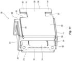
- the rear end 206 of the main body 202 is not orthogonal to the longitudinal axis F extending through the main body 202. See, e.g., Fig. 11 . Rather, it has an angle that matches the angle at the front of the housing 406. One will be able to discern from this angled surface, where the first projection 230 and the second projection 240 are within the main body 202. This will allow for the multi-fiber ferrule 100 to be inserted so that the first projection 230 and the second projection 240 engage correct ones of the forward facing surfaces 132, 152 in the multi-fiber ferrule 100. See, e.g., Figs. 12 and 15 .
- the tabs 250 Extending from the rear end 206, and away from the main body 202, are two tabs 250, one is mounted on side 208 and the other on side 210.
- the two tabs 250 each have a shape of the letter "T".
- the tabs 250 have cut-outs 252 which form legs 254.
- the tabs 250 and the legs 254 are able to flex outward from the opening 216 and engage the housing 406 as described below. See also Figs. 15 and 16 .
- the tabs 250 have a rear surface 256 that is perpendicular to the longitudinal axis F.
- the cut-outs 252 between the tab 205 and the legs 254 are not rectangular, but are trapezoidal, allowing the rear end 206 to be angled, while still having the rear surface 256 and the front end 204 perpendicular to the longitudinal axis F.
- the housing 406 will now be described with reference to Figs. 18-28 .
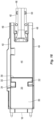
- the housing 406 has a main body 420 that extends between a front end 422 and a rear end 424 and generally has three sections.
- the housing 406 also has an opening 426 that extends between the front end 422 and the rear end 424.
- the first section 428 is a front section that receives an elastic member such as spring 404.
- the elastic member or spring 404 is to engage, directly or indirectly, the rear end of the multi-fiber ferrule 100 and bias it in a forward direction.
- the spring 404 engages forward facing surfaces 430 that extend into the opening 426 from the interior surface 432 and function as an integral spring stop. Referring to Fig.
- FIG. 20 in the cross-section, two of the forward facing surfaces 430 are illustrated, each continuing around one side of the housing 406 internally (see also Fig. 21 ) on the other half of the main body 420 that is not visible.
- the front end 422 has a chamfered surface 434 that assists in inserting the spring 404 during the initial insertion as well as movement of the spring 404 during use of the housing 406 in the fiber optic connector 400.
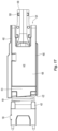
- the main body 420 of the housing 406 has a plurality of shoulders 460 that extending from the front end 422 to the rear end 424.
- the shoulders are generally at the corners of the main body 420, where first side 440 meets with top side 462 and bottom side 464 and second side 442 meets with top side 462 and bottom side 464.
- These shoulders 460 act as a guide to align the fiber optic connector 400 with another receptacle, such as an adapter.
- the shoulders 460 also match with the shoulders 260 on the fiber optic ferrule receiver 200 to form a continuous shoulder at each corner.
- the second or middle section 470 provides an area for the optical fibers 300 to transition from a flat ribbon to a grouping that can be protected by a round fiber optic cable covering.
- the optical fibers 300 extend from the multi-fiber ferrule 100 in a flat configuration, the middle section 470 allows for them to be grouped together to pass out the rear end 424 in circular configuration and in a cable sheath 302.
- the optical fibers 300 cannot be bent beyond their bend radius without damaging the optical fibers 300.
- This transition area 470 assists in preventing such damage.
- the transition area 470 is dimensioned to maintain a safe bend radius for the individual optical fibers 300 as these optical fibers 300 transition from a ribbon form to a fiber optic cable form with loose fibers therein.
- the third or rear section 480 is used to finalize the configuration of the optical fibers 300 from the transition area in the middle section 470 to the cable format.
- the rear section 480 has an outer surface 482 to engage the crimp ring 408.
- the outer surface 482 is on a circular extension or crimp body 486 that extends from the rear end 424.
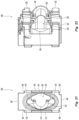
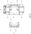
- the crimp body 486 is preferably made from two portions, a first portion 490 that is integral with the main body 420 and a second portion 492 that is removable from the main body 420 and the first portion 490. See Figs. 19-20 and 23-24 .
- the second portion 492 has a rear section 494 that is a half cylinder and a forward section 496 that mates with the main body 420 to close the middle section 470.
- the rear portion 494 mates with the first portion 490 to form the cylindrical shape that can accept the crimp ring 408.
- the rear section 494 mates with the first portion 490 with a series of projections 500 and recesses 502. As illustrated in the figures, the projections 500 are on the first portion 490 and the recesses 502 are on the second portion 492. However, the projections and recesses could be reversed or mixed with regard to their positions on the first portion 490 and the second portion 492.
- the projections 500 preferably frictionally engage the recesses 502 and then once the crimp ring 408 is secured around the crimp body 486, the two portions 490,492 will not move relative to one another.
- the forward section 496 of the second portion 492 mates with the main body 420 of the housing 406.
- the main body 420 has an extra portion 504 that has been cut out to allow for more optical fibers and larger groups of optical fibers to pass through the opening 426. This makes the opening 426 at the forward section 496 larger than on the opposing side..
- the larger opening 426 allows the housing 406 to be installed onto the cable and slid down the cable and out of the way during termination and polishing of the ferrule 100. That is when viewed straight into the opening 426 from the rear section 494, or even from the front end 422, the opening 426 is asymmetrical due to the presence of the first portion 490 and the extra portion 504. See Figs. 22 , 23 .
- the forward section 496 of the crimp body 486 has a tab 506 that extends into the extra portion 504 to close it off when the two portions 490,492 are mated.
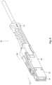
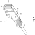
- the housing 406 also has a number of latches 520 that extend from the main body 420 to engage a push-pull boot 410 and more specifically two latches 522 on the push-pull boot. See Figs. 9 , 10 , 24 , and 27 . As illustrated, the latches 522 on the push-pull boot can slide in the area 524 between two latches 520 on each side of the housing 406. See Fig. 27 . When the push-pull boot 410 is pulled, the latches 522 slide within the area 524 until they reach the end of the latches 520 and at this point, the force is transferred to the latches 520 and the housing 406 to remove the fiber optic connector from its receiver.
- the push-pull boot 410 is pushed until the latches 522 engage the front end of the area 524, which then transfers to the housing 406 and moves the fiber optic connector in a forward direction to secure it within a receptacle.
- FIG. 39 there is a housing 406a that has a second portion 492a of a crimp body 486a and a latch 520a molded thereon.
- the housing 406a has the same components as the housing discussed above, as well as the extra portion 504' that has been cut out to allow for more optical fibers and larger groups of optical fibers to be used with this housing 406a.
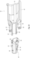
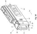
- FIGs. 29-34 Another embodiment of a housing 406' and a fiber optic ferrule receiver 200' according to the present invention are illustrated in Figs. 29-34 .
- the fiber optic ferrule that is used in these figures corresponds to multi-fiber ferrule 100 discussed above, but another fiber optic ferrule could also be used.
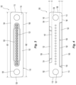
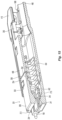
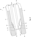
- This embodiment of a fiber optic ferrule receiver 200' includes a main body 202' extending between a front end 204' and a rear end 206'.
- the main body 202' also has four sides 208',210',212',214', and an opening 216' extending between the front end 204' and the rear end 206' and being defined at least by a portion of internal surfaces of the four sides 208',210',212',214'.
- the fiber optic ferrule receiver 200' also includes two tabs 250' that extend rearwardly from the rear end 206'.
- the two tabs 250' each have a projection 252' that extend outwardly and away from each other.
- the projections 252' are designed to engage an opening 444' on each side of the housing 406', as described in more detail below.
- the two tabs 250' are somewhat flexible in that they can flex inward to be inserted into the housing 406' and subsequently return, at least partially, to their pre-flexed configuration. This allows the fiber optic ferrule receiver 200' to be retained in the housing 406'.
- the length of fiber optic ferrule receiver 200' (the distance between the front end 204' and the rear end 206') is shorter than that of fiber optic ferrule receiver 200.
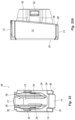
- the housing 406' is therefore longer so that the combination of the housing 406' and the fiber optic ferrule receiver 200' are preferably the same overall length. It is also clear from Fig. 33A that the rear end 206' of the a fiber optic ferrule receiver 200' and the front end of the housing 406' are slanted as in the previous embodiment for the purposes of polarity.
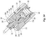
- the opening 216' of the fiber optic ferrule receiver 200' has the same general configuration of a fiber optic ferrule receiver 200. That is, first side 208' and second side 210' are on opposite sides of the opening 216', while third side 212' and fourth side 214' are each connected to the first side 208' and the second side 210' and are opposite each other about the opening 216'. Third side 212' and fourth side 214' have internal surfaces that are preferably flat and linear, but they may have tapering features discussed above.
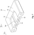
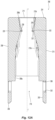
- First side 208' has a first tapered surface 208a' in the opening 216' as well as a second tapered surface 208b', the first tapered surface 208a' reducing the opening 216' between the rear end 206' and a first position 220', and the second tapered surface 208b' increasing the opening 216' between the first position 220' and the front end 204'. See Fig. 34 .
- the first tapered surface 208a' may have a number of ramped and flat portions.
- the first tapered surface 208a' is to prevent the front end 114 of the main body 102 of the multi-fiber ferrule 100 from encountering any surface that causes damage to the front end 114 or causes the multi-fiber ferrule 100 from catching as it is inserted into the opening 216'.
- Second side 210' also has a third tapered surface 210a' in the opening 216' as well as a fourth tapered surface 210b', the third tapered surface 210a' reducing the opening 216' between the rear end 206' and a second position 222', and the fourth tapered surface 210b' increasing the opening 216' between the second position 222' and the front end 204'.
- the first position 220' and the second position 222' are directly across the opening 216' from each other.
- the first position 220' and the second position 222' may be off set from one another.
- the first portion 220' and the second portion 222' can be thought of as a line (that may have a number of thicknesses) that extends across the opening 416' between the third side 212' and the fourth side 214' and on the first side 208' and the second side 210', respectively.
- the first portion 220' and the second portion 222' can also be a plane rather than a line.
- the fiber optic ferrule receiver 200' has a first projection 230' extending into the opening 216' from the first side 208' to engage the multi-fiber ferrule 100 at the first position 220'.
- the first projection 230' engages the first forward facing surface 132 of the multi-fiber ferrule 100.
- the ferrule receiver 200' has a second projection 240' extending into the opening 216' from the second side 210' to engage the multi-fiber ferrule 100' at the second position 222'.
- the second projection 240' engages the second forward facing surface 152 of the multi-fiber ferrule 100.
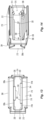
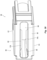
- the housing 406' also has an opening 426' that extends between the front end 422' and the rear end 424'.
- the first section 428' receives an elastic member such as spring 404.
- the elastic member or spring 404 is to engage, directly or indirectly, the rear end of the multi-fiber ferrule 100 and bias it in a forward direction.
- the spring 404 engages forward facing surfaces 430' that extend into the opening 426' from the interior surface 432' and function as an integral spring stop. Referring to Fig. 31 , two of the forward facing surfaces 430' are illustrated.
- the front end 422' has a chamfered surface 434' that assists in inserting the spring 404 during the initial insertion as well as movement of the spring 404 during use of the housing 406' in a fiber optic connector 400.
- the opening 426' is illustrated as being oval in cross section, but it could have other configurations as needed.
- a depression 448' that also has the opening 444' to receive the projections 252' from the tabs 250' when the fiber optic ferrule receiver 200' is inserted into the opening 426'.
Landscapes
- Physics & Mathematics (AREA)
- General Physics & Mathematics (AREA)
- Optics & Photonics (AREA)
- Mechanical Coupling Of Light Guides (AREA)
- Optical Couplings Of Light Guides (AREA)
- Connector Housings Or Holding Contact Members (AREA)
Applications Claiming Priority (4)
| Application Number | Priority Date | Filing Date | Title |
|---|---|---|---|
| US202063014491P | 2020-04-23 | 2020-04-23 | |
| US202063047657P | 2020-07-02 | 2020-07-02 | |
| EP21725885.4A EP4139726B1 (de) | 2020-04-23 | 2021-04-23 | Faseroptische ferrule und faseroptischer ferruleempfänger |
| PCT/US2021/028925 WO2021217054A1 (en) | 2020-04-23 | 2021-04-23 | Fiber optic ferrule and fiber optic ferrule receiver |
Related Parent Applications (2)
| Application Number | Title | Priority Date | Filing Date |
|---|---|---|---|
| EP21725885.4A Division-Into EP4139726B1 (de) | 2020-04-23 | 2021-04-23 | Faseroptische ferrule und faseroptischer ferruleempfänger |
| EP21725885.4A Division EP4139726B1 (de) | 2020-04-23 | 2021-04-23 | Faseroptische ferrule und faseroptischer ferruleempfänger |
Publications (2)
| Publication Number | Publication Date |
|---|---|
| EP4579300A2 true EP4579300A2 (de) | 2025-07-02 |
| EP4579300A3 EP4579300A3 (de) | 2025-09-17 |
Family
ID=75914599
Family Applications (6)
| Application Number | Title | Priority Date | Filing Date |
|---|---|---|---|
| EP21725887.0A Active EP4139727B1 (de) | 2020-04-23 | 2021-04-23 | Gehäuse für einen faseroptischen stecker |
| EP21725885.4A Active EP4139726B1 (de) | 2020-04-23 | 2021-04-23 | Faseroptische ferrule und faseroptischer ferruleempfänger |
| EP25166348.0A Pending EP4553550A3 (de) | 2020-04-23 | 2021-04-23 | Miniatur-multifaser-ferrule |
| EP24217512.3A Pending EP4495648A3 (de) | 2020-04-23 | 2021-04-23 | Gehäuse für einen faseroptischen stecker |
| EP25176345.4A Pending EP4579300A3 (de) | 2020-04-23 | 2021-04-23 | Faseroptische ferrule und faseroptischer ferruleempfänger |
| EP21725638.7A Active EP4139725B1 (de) | 2020-04-23 | 2021-04-23 | Miniatur-multifaser-ferrule |
Family Applications Before (4)
| Application Number | Title | Priority Date | Filing Date |
|---|---|---|---|
| EP21725887.0A Active EP4139727B1 (de) | 2020-04-23 | 2021-04-23 | Gehäuse für einen faseroptischen stecker |
| EP21725885.4A Active EP4139726B1 (de) | 2020-04-23 | 2021-04-23 | Faseroptische ferrule und faseroptischer ferruleempfänger |
| EP25166348.0A Pending EP4553550A3 (de) | 2020-04-23 | 2021-04-23 | Miniatur-multifaser-ferrule |
| EP24217512.3A Pending EP4495648A3 (de) | 2020-04-23 | 2021-04-23 | Gehäuse für einen faseroptischen stecker |
Family Applications After (1)
| Application Number | Title | Priority Date | Filing Date |
|---|---|---|---|
| EP21725638.7A Active EP4139725B1 (de) | 2020-04-23 | 2021-04-23 | Miniatur-multifaser-ferrule |
Country Status (4)
| Country | Link |
|---|---|
| US (7) | US12019278B2 (de) |
| EP (6) | EP4139727B1 (de) |
| CN (3) | CN115516355A (de) |
| WO (3) | WO2021217057A1 (de) |
Families Citing this family (22)
| Publication number | Priority date | Publication date | Assignee | Title |
|---|---|---|---|---|
| EP3729153B1 (de) * | 2017-12-19 | 2024-07-10 | US Conec, Ltd | Mini-duplex-verbinder mit gegentaktpolaritätsmechanismus und träger |
| US12321017B2 (en) | 2020-04-23 | 2025-06-03 | Us Conec Ltd. | Fiber optic ferrule and fiber optic ferrule receiver |
| EP4139727B1 (de) | 2020-04-23 | 2025-07-23 | US Conec, Ltd | Gehäuse für einen faseroptischen stecker |
| US11650379B2 (en) | 2020-10-14 | 2023-05-16 | Us Conec Ltd. | Anti-buckling latch for a fiber optic connector |
| EP4314917A1 (de) | 2021-04-02 | 2024-02-07 | US Conec, Ltd | Ferrulenhalter für miniatur-mt-ferrule und adapterschnittstelle zur verbindung mit glasfasersteckern |
| US12523821B2 (en) | 2021-04-08 | 2026-01-13 | Commscope Technologies Llc | Telecommunications connector with latch release mechanism |
| US12078854B2 (en) | 2021-04-23 | 2024-09-03 | US Conec, Ltd | Optical assembly |
| US12130480B2 (en) | 2021-05-17 | 2024-10-29 | Us Conec Ltd. | Polarity scheme for multi-fiber connectors with a connector key |
| EP4409343A4 (de) * | 2021-09-30 | 2025-10-22 | Senko Advanced Components Inc | Faseroptische netzwerksysteme |
| US12366711B2 (en) | 2021-12-08 | 2025-07-22 | Us Conec Ltd. | Small form factor fiber optic connector dust cap |
| WO2023122215A1 (en) | 2021-12-22 | 2023-06-29 | US Conec, Ltd | Fiber optic connector with mechanical advantage |
| US12422627B2 (en) | 2022-05-02 | 2025-09-23 | Us Conec Ltd. | Data center interconnect for optical trunk cables having miniature multi-fiber ferrules |
| US12546954B2 (en) | 2022-05-31 | 2026-02-10 | Us Conec Ltd. | Fiber cable jacket retention features for VSFF fiber-optic connectors |
| US20250370195A1 (en) | 2022-07-20 | 2025-12-04 | Us Conec Ltd. | Mpo connector with non-mt multi-fiber ferrule and sleeve therefor |
| WO2024044060A1 (en) | 2022-08-22 | 2024-02-29 | Corning Research & Development Corporation | Multi-fiber ferrule with tapered transition into ferrule bore |
| US20240085636A1 (en) | 2022-09-13 | 2024-03-14 | Us Conec Ltd. | Optical Assembly with Adapter for Intermating Different Multi-Fiber Ferrule Formats within the Adapter |
| WO2024247936A1 (ja) * | 2023-05-31 | 2024-12-05 | 株式会社フジクラ | 多心光コネクタ |
| USD1094314S1 (en) * | 2023-07-14 | 2025-09-23 | Senko Advanced Components, Inc. | MT ferrule |
| USD1102389S1 (en) * | 2023-10-26 | 2025-11-18 | Hakusan Inc. | Optical connector |
| WO2025126615A1 (ja) * | 2023-12-15 | 2025-06-19 | 株式会社フジクラ | 光コネクタ |
| WO2025175183A1 (en) | 2024-02-14 | 2025-08-21 | Us Conec Ltd. | Mass insertion of optical fibers to active area device |
| WO2025222088A1 (en) | 2024-04-18 | 2025-10-23 | Us Conec Ltd. | Lensed ferrules for compact optical connectors |
Citations (1)
| Publication number | Priority date | Publication date | Assignee | Title |
|---|---|---|---|---|
| WO2019195652A1 (en) | 2018-04-06 | 2019-10-10 | US Conec, Ltd | Flexible push-pull boot and crimp body for fiber optic connector |
Family Cites Families (71)
| Publication number | Priority date | Publication date | Assignee | Title |
|---|---|---|---|---|
| US4178068A (en) * | 1977-11-14 | 1979-12-11 | Amp Incorporated | Fiber optic cable termination means |
| US4762389A (en) * | 1984-03-30 | 1988-08-09 | Nec Corporation | Optical fiber connector |
| US5016970A (en) * | 1989-08-22 | 1991-05-21 | Nippon Telegraph And Telephone Corp. | Ferrule for optical fiber transmitting linearly polarized light and optical fiber connector using this ferrule |
| US5746764A (en) * | 1995-12-04 | 1998-05-05 | Atrion Medical Products, Inc. | Stent compression instrument |
| JP3571863B2 (ja) * | 1996-10-16 | 2004-09-29 | 古河電気工業株式会社 | 光コネクタの光ファイバ突出長設定方法およびその治具 |
| JP3370908B2 (ja) * | 1997-08-18 | 2003-01-27 | 株式会社フジクラ | 光コネクタ |
| JPH11109161A (ja) | 1997-09-30 | 1999-04-23 | Sumitomo Electric Ind Ltd | 光ファイバアレイ、フェルール及びこのフェルールを利用した光コネクタ |
| US6154597A (en) | 1998-01-05 | 2000-11-28 | Molex Incorporated | Fiber optic termination system including a fiber optic connector assembly and method of fabricating same |
| US6435730B1 (en) * | 1998-05-06 | 2002-08-20 | The Whitaker Corporation | Optical fiber connector with improved ferrule float feature |
| US6085003A (en) * | 1998-07-28 | 2000-07-04 | Us Conec Ltd | Multifiber connector having a free floating ferrule |
| US6106162A (en) * | 1998-11-12 | 2000-08-22 | Delphi Technologies Inc. | Glass optical fiber bundle connector for a hybrid fiber optic lighting distribution system |
| US6195477B1 (en) * | 1998-11-12 | 2001-02-27 | Delphi Technologies, Inc. | Hybrid fiber optic lighting distribution system |
| EP1039323A1 (de) * | 1999-03-23 | 2000-09-27 | W.L. GORE & ASSOCIATES | Steckerstift für optische Fasern |
| US6357933B1 (en) * | 1999-03-30 | 2002-03-19 | Lucent Technologies Inc. | Quick connect optical fiber ferrule connector |
| US6547449B1 (en) | 1999-12-17 | 2003-04-15 | Corning Cable Systems Llc | Windowless, rectangular ferrule in a preassembled multifiber connector and associated assembly method |
| US6412988B1 (en) | 1999-12-30 | 2002-07-02 | Corning Cable Systems Llc | Ferrule and fiber optic connector housing having enlarged shoulders |
| JP3917378B2 (ja) * | 2001-01-17 | 2007-05-23 | 株式会社オートネットワーク技術研究所 | 光ファイバ端末処理方法及び光ファイバ端末処理装置 |
| US6422760B1 (en) * | 2001-01-31 | 2002-07-23 | Molex Incorporated | Fiber optic connector module |
| US6663293B2 (en) * | 2001-03-16 | 2003-12-16 | Fitel Usa Corp. | Tunable optical fiber connector |
| JP2002318324A (ja) * | 2001-04-20 | 2002-10-31 | Furukawa Electric Co Ltd:The | 光コネクタフェルール用ハウジング、ハウジング付き光コネクタフェルール、光コネクタ |
| US7036993B2 (en) | 2001-06-11 | 2006-05-02 | Corning Cable Systems Llc | Pin retainer for fiber optic connector and associated fabrication method |
| US6893165B2 (en) * | 2002-03-01 | 2005-05-17 | Fci Americas Technology, Inc. | Optic fiber connectors and coupling sleeve |
| US6705765B2 (en) * | 2002-05-20 | 2004-03-16 | Fitel Usa Corp. | Polarization maintaining optical fiber connector plug |
| US6957920B2 (en) * | 2002-06-24 | 2005-10-25 | Corning Cable Systems Llc | Ferrule assembly having highly protruding optical fibers and an associated fabrication method |
| JP2004038005A (ja) * | 2002-07-05 | 2004-02-05 | Akutowan:Kk | フェルール及びフェルールの製造方法 |
| US7393142B2 (en) * | 2003-08-29 | 2008-07-01 | Corning Cable Systems Llc | Molded ferrule with reference surface for end face geometry measurement |
| US20050036742A1 (en) * | 2003-08-29 | 2005-02-17 | Dean David L. | Molded fiber optic ferrule with integrally formed geometry features |
| US7785019B2 (en) * | 2005-03-10 | 2010-08-31 | Corning Cable Systems Llc | Multi-fiber fiber optic receptacle and plug assembly |
| US8104973B2 (en) | 2007-02-09 | 2012-01-31 | Us Conec, Ltd. | Ferrule-to-ferrule adapter and ferrule adapter assembly |
| US7540666B2 (en) | 2007-02-27 | 2009-06-02 | Corning Cable Systems Llc | Articulated force application for multi-fiber ferrules |
| US20090041412A1 (en) | 2007-08-07 | 2009-02-12 | Jeffrey Dean Danley | Laser erosion processes for fiber optic ferrules |
| US8109679B2 (en) * | 2008-11-25 | 2012-02-07 | Corning Cable Systems Llc | Optical ferrule assemblies and methods of making the same |
| US7841778B2 (en) | 2008-12-19 | 2010-11-30 | The Furukawa Electric Co., Ltd. | Optical connector |
| US8337093B2 (en) * | 2009-09-30 | 2012-12-25 | Corning Cable Systems Llc | Fiber optic connectors and methods for making the same |
| CN102346279B (zh) * | 2010-07-30 | 2015-03-11 | 株式会社藤仓 | 光连接器、连接器连接系统 |
| WO2012064594A1 (en) | 2010-11-09 | 2012-05-18 | Corning Cable Systems Llc | Ferrules having optical pathways and fiber optic connectors using same |
| TWM450737U (zh) * | 2011-06-14 | 2013-04-11 | Molex Inc | 光纖組件 |
| US8540435B2 (en) * | 2011-07-22 | 2013-09-24 | Corning Cable Systems Llc | Ferrule retainers having access window(s) for accessing and/or referencing a fiber optic ferrule, and related fiber optic connector assemblies, connectors, and referencing methods |
| EP2756344A2 (de) * | 2011-09-13 | 2014-07-23 | Corning Cable Systems LLC | Übertragungslinsenhalteranordnungen mit bohrungsentlastungszonen und optische stecker damit |
| US8534928B2 (en) * | 2011-11-28 | 2013-09-17 | Corning Cable Systems Llc | Optical fiber assemblies, optical fiber organizers and methods of fabricating optical fiber assemblies |
| US9529155B2 (en) * | 2012-11-28 | 2016-12-27 | Corning Optical Communications LLC | Gradient index (GRIN) lens chips and associated small form factor optical arrays for optical connections, related fiber optic connectors |
| US9551841B2 (en) * | 2012-11-30 | 2017-01-24 | Corning Optical Communications LLC | Optical data center connector systems, fiber optic plug assemblies, and fiber optic receptacle assemblies |
| US9028154B2 (en) * | 2013-02-01 | 2015-05-12 | Avago Technologies General Ip (Singapore) Pte. Ltd. | Adapter for cleaning an optical junction and reducing optical back reflection |
| WO2014123873A1 (en) * | 2013-02-05 | 2014-08-14 | Commscope, Inc. Of North Carolina | Methods of connectorizing multi-core fiber optic cables and related apparatus |
| US10495824B2 (en) * | 2014-05-16 | 2019-12-03 | Joel C. Rosson | Optical connector element |
| FR3021415A1 (fr) | 2014-05-21 | 2015-11-27 | Radiall Sa | Ferule de dimensions reduites pour contact optique, connecteur multi-contacts integrant une pluralite de telles ferules. |
| CN208140982U (zh) | 2014-10-03 | 2018-11-23 | 康宁光电通信有限责任公司 | 用于光纤连接器的套圈组件、光纤连接器及光纤电缆组件 |
| WO2016072330A1 (ja) | 2014-11-07 | 2016-05-12 | Seiオプティフロンティア株式会社 | 光コネクタ、ピンキーパー、ピン挿入用治具、拡張部材及びピン挿入具 |
| US9568689B2 (en) * | 2015-02-18 | 2017-02-14 | US Conec, Ltd | Spring push and push-pull tab for tightly spaced fiber optic connectors |
| US10197743B2 (en) * | 2015-05-22 | 2019-02-05 | US Conec, Ltd | Multi-fiber ferrule with improved eye safety |
| EP4403972A3 (de) * | 2015-11-30 | 2024-10-16 | CommScope Technologies LLC | Faseroptischer verbinder und dessen zusammenbau |
| US10191227B2 (en) * | 2016-01-20 | 2019-01-29 | Alliance Fiber Optics Products, Inc. | Fiber optic connector with small profile, and cable assemblies, systems, and methods including the same |
| US10156683B2 (en) * | 2016-04-11 | 2018-12-18 | Leviton Manufacturing Co., Inc. | Polarity identification for polarity reversing duplex unibody connectors |
| TWI608262B (zh) * | 2016-11-30 | 2017-12-11 | 林雨晴 | 光纖連接器 |
| WO2018116855A1 (ja) | 2016-12-19 | 2018-06-28 | 株式会社フジクラ | フェルール、光ファイバ付きフェルール、及び光ファイバ付きフェルールの製造方法 |
| US10451830B2 (en) * | 2016-12-29 | 2019-10-22 | Corning Optical Communications LLC | Fiber optic cable assembly and fabrication method using sequentially arranged boots for multi-fiber ferrule |
| US10725248B2 (en) * | 2017-01-30 | 2020-07-28 | Senko Advanced Components, Inc. | Fiber optic receptacle with integrated device therein incorporating a behind-the-wall fiber optic receptacle |
| US10185100B2 (en) | 2017-01-30 | 2019-01-22 | Senko Advanced Components, Inc | Modular connector and adapter assembly using a removable anchor device |
| US20190361177A1 (en) * | 2017-01-31 | 2019-11-28 | Sei Optifrontier Co., Ltd. | Optical connector and optical fiber with connector |
| EP3596520B1 (de) * | 2017-03-16 | 2022-04-27 | Corning Research & Development Corporation | Anordnungen anlösbarer optischer verbinder und optischer chips |
| US10281669B2 (en) | 2017-07-14 | 2019-05-07 | Senko Advance Components, Inc. | Ultra-small form factor optical connectors |
| JP6858108B2 (ja) | 2017-10-03 | 2021-04-14 | 株式会社フジクラ | 光コネクタ及びフェルール |
| US11002923B2 (en) * | 2017-11-21 | 2021-05-11 | Senko Advanced Components, Inc. | Fiber optic connector with cable boot release having a two-piece clip assembly |
| EP3729153B1 (de) * | 2017-12-19 | 2024-07-10 | US Conec, Ltd | Mini-duplex-verbinder mit gegentaktpolaritätsmechanismus und träger |
| US10948663B2 (en) | 2018-06-05 | 2021-03-16 | Panduit Corp. | Small form factor multi-fiber connector |
| JPWO2020149262A1 (ja) * | 2019-01-15 | 2021-11-25 | 住友電気工業株式会社 | 光コネクタおよび光接続構造 |
| US11340406B2 (en) * | 2019-04-19 | 2022-05-24 | Senko Advanced Components, Inc. | Small form factor fiber optic connector with resilient latching mechanism for securing within a hook-less receptacle |
| US11194107B2 (en) | 2019-08-20 | 2021-12-07 | Corning Incorporated | High-density FAUs and optical interconnection devices employing small diameter low attenuation optical fiber |
| US11353664B1 (en) | 2019-08-21 | 2022-06-07 | Senko Advanced Components, Inc. | Fiber optic connector |
| US11243361B2 (en) | 2019-12-18 | 2022-02-08 | Viavi Solutions France SAS | Mechanical transfer ferrule based optical switch |
| EP4139727B1 (de) | 2020-04-23 | 2025-07-23 | US Conec, Ltd | Gehäuse für einen faseroptischen stecker |
-
2021
- 2021-04-23 EP EP21725887.0A patent/EP4139727B1/de active Active
- 2021-04-23 WO PCT/US2021/028929 patent/WO2021217057A1/en not_active Ceased
- 2021-04-23 EP EP21725885.4A patent/EP4139726B1/de active Active
- 2021-04-23 EP EP25166348.0A patent/EP4553550A3/de active Pending
- 2021-04-23 WO PCT/US2021/028925 patent/WO2021217054A1/en not_active Ceased
- 2021-04-23 CN CN202180030131.2A patent/CN115516355A/zh active Pending
- 2021-04-23 CN CN202180028531.XA patent/CN115427857A/zh active Pending
- 2021-04-23 EP EP24217512.3A patent/EP4495648A3/de active Pending
- 2021-04-23 US US17/908,430 patent/US12019278B2/en active Active
- 2021-04-23 EP EP25176345.4A patent/EP4579300A3/de active Pending
- 2021-04-23 EP EP21725638.7A patent/EP4139725B1/de active Active
- 2021-04-23 WO PCT/US2021/028919 patent/WO2021217050A1/en not_active Ceased
- 2021-04-23 CN CN202180030573.7A patent/CN115461662A/zh active Pending
- 2021-04-23 US US17/918,058 patent/US11914195B2/en active Active
- 2021-04-23 US US17/918,067 patent/US12061362B2/en active Active
-
2024
- 2024-04-21 US US18/641,400 patent/US12379549B2/en active Active
- 2024-07-26 US US18/785,303 patent/US20240385387A1/en active Pending
-
2025
- 2025-05-01 US US19/196,010 patent/US20250258342A1/en active Pending
- 2025-07-07 US US19/261,655 patent/US20250334748A1/en active Pending
Patent Citations (1)
| Publication number | Priority date | Publication date | Assignee | Title |
|---|---|---|---|---|
| WO2019195652A1 (en) | 2018-04-06 | 2019-10-10 | US Conec, Ltd | Flexible push-pull boot and crimp body for fiber optic connector |
Also Published As
| Publication number | Publication date |
|---|---|
| EP4139726A1 (de) | 2023-03-01 |
| EP4139727A1 (de) | 2023-03-01 |
| CN115427857A (zh) | 2022-12-02 |
| US20250334748A1 (en) | 2025-10-30 |
| US12061362B2 (en) | 2024-08-13 |
| US11914195B2 (en) | 2024-02-27 |
| US12379549B2 (en) | 2025-08-05 |
| US20250258342A1 (en) | 2025-08-14 |
| EP4553550A3 (de) | 2025-06-25 |
| WO2021217054A1 (en) | 2021-10-28 |
| EP4139726B1 (de) | 2025-06-25 |
| US20230161116A1 (en) | 2023-05-25 |
| EP4139725B1 (de) | 2025-04-02 |
| EP4495648A2 (de) | 2025-01-22 |
| EP4579300A3 (de) | 2025-09-17 |
| US20240264383A1 (en) | 2024-08-08 |
| WO2021217050A1 (en) | 2021-10-28 |
| EP4139725A1 (de) | 2023-03-01 |
| WO2021217057A1 (en) | 2021-10-28 |
| CN115461662A (zh) | 2022-12-09 |
| US20230091327A1 (en) | 2023-03-23 |
| US20230161115A1 (en) | 2023-05-25 |
| EP4139727B1 (de) | 2025-07-23 |
| US20240385387A1 (en) | 2024-11-21 |
| EP4553550A2 (de) | 2025-05-14 |
| EP4495648A3 (de) | 2025-03-19 |
| US12019278B2 (en) | 2024-06-25 |
| CN115516355A (zh) | 2022-12-23 |
Similar Documents
| Publication | Publication Date | Title |
|---|---|---|
| EP4139726B1 (de) | Faseroptische ferrule und faseroptischer ferruleempfänger | |
| EP3330758B1 (de) | Glasfaserstecker | |
| US11592626B2 (en) | Fiber optic connector with boot-integrated release and related assemblies | |
| EP1122566B1 (de) | Faseroptisches Verbindungssystem | |
| CN100388028C (zh) | 连接器组件夹子 | |
| US5315679A (en) | Optical fibers duplex connector assembly | |
| US11971583B2 (en) | Secure MT ferrule latching with MPO adapter | |
| US20240085636A1 (en) | Optical Assembly with Adapter for Intermating Different Multi-Fiber Ferrule Formats within the Adapter | |
| KR20130004236U (ko) | 상보적인 짝맞춤 형상부를 갖는 페룰 및 관련 섬유 광학 컨넥터 | |
| EP4314918B1 (de) | Ferrulenhalter für miniatur-mt-ferrule und adapterschnittstelle zur verbindung mit glasfasersteckern | |
| US12321017B2 (en) | Fiber optic ferrule and fiber optic ferrule receiver | |
| AU2018360319B2 (en) | Shroud for SC optical connector | |
| CN110031939B (zh) | 具有模块化闩锁臂的窄宽度适配器和连接器 | |
| CN100468107C (zh) | 键固光纤连接器 | |
| WO2022081547A1 (en) | Multi-fiber connector system | |
| WO2022178017A1 (en) | Low-profile telecommunications connectors |
Legal Events
| Date | Code | Title | Description |
|---|---|---|---|
| PUAI | Public reference made under article 153(3) epc to a published international application that has entered the european phase |
Free format text: ORIGINAL CODE: 0009012 |
|
| STAA | Information on the status of an ep patent application or granted ep patent |
Free format text: STATUS: THE APPLICATION HAS BEEN PUBLISHED |
|
| AC | Divisional application: reference to earlier application |
Ref document number: 4139726 Country of ref document: EP Kind code of ref document: P |
|
| AK | Designated contracting states |
Kind code of ref document: A2 Designated state(s): AL AT BE BG CH CY CZ DE DK EE ES FI FR GB GR HR HU IE IS IT LI LT LU LV MC MK MT NL NO PL PT RO RS SE SI SK SM TR |
|
| PUAL | Search report despatched |
Free format text: ORIGINAL CODE: 0009013 |
|
| AK | Designated contracting states |
Kind code of ref document: A3 Designated state(s): AL AT BE BG CH CY CZ DE DK EE ES FI FR GB GR HR HU IE IS IT LI LT LU LV MC MK MT NL NO PL PT RO RS SE SI SK SM TR |
|
| RIC1 | Information provided on ipc code assigned before grant |
Ipc: G02B 6/38 20060101AFI20250812BHEP |
|
| STAA | Information on the status of an ep patent application or granted ep patent |
Free format text: STATUS: REQUEST FOR EXAMINATION WAS MADE |
|
| 17P | Request for examination filed |
Effective date: 20260123 |