EP4579320A1 - Motor, kameramodul und elektronische vorrichtung - Google Patents
Motor, kameramodul und elektronische vorrichtung Download PDFInfo
- Publication number
- EP4579320A1 EP4579320A1 EP24755946.1A EP24755946A EP4579320A1 EP 4579320 A1 EP4579320 A1 EP 4579320A1 EP 24755946 A EP24755946 A EP 24755946A EP 4579320 A1 EP4579320 A1 EP 4579320A1
- Authority
- EP
- European Patent Office
- Prior art keywords
- image stabilization
- piece
- magnetic
- bracket
- focusing
- Prior art date
- Legal status (The legal status is an assumption and is not a legal conclusion. Google has not performed a legal analysis and makes no representation as to the accuracy of the status listed.)
- Pending
Links
Images














Classifications
-
- H—ELECTRICITY
- H04—ELECTRIC COMMUNICATION TECHNIQUE
- H04M—TELEPHONIC COMMUNICATION
- H04M1/00—Substation equipment, e.g. for use by subscribers
- H04M1/02—Constructional features of telephone sets
- H04M1/0202—Portable telephone sets, e.g. cordless phones, mobile phones or bar type handsets
- H04M1/026—Details of the structure or mounting of specific components
- H04M1/0264—Details of the structure or mounting of specific components for a camera module assembly
-
- G—PHYSICS
- G02—OPTICS
- G02B—OPTICAL ELEMENTS, SYSTEMS OR APPARATUS
- G02B27/00—Optical systems or apparatus not provided for by any of the groups G02B1/00 - G02B26/00, G02B30/00
- G02B27/64—Imaging systems using optical elements for stabilisation of the lateral and angular position of the image
- G02B27/646—Imaging systems using optical elements for stabilisation of the lateral and angular position of the image compensating for small deviations, e.g. due to vibration or shake
-
- G—PHYSICS
- G02—OPTICS
- G02B—OPTICAL ELEMENTS, SYSTEMS OR APPARATUS
- G02B7/00—Mountings, adjusting means, or light-tight connections, for optical elements
- G02B7/02—Mountings, adjusting means, or light-tight connections, for optical elements for lenses
- G02B7/04—Mountings, adjusting means, or light-tight connections, for optical elements for lenses with mechanism for focusing or varying magnification
- G02B7/08—Mountings, adjusting means, or light-tight connections, for optical elements for lenses with mechanism for focusing or varying magnification adapted to co-operate with a remote control mechanism
-
- G—PHYSICS
- G02—OPTICS
- G02B—OPTICAL ELEMENTS, SYSTEMS OR APPARATUS
- G02B7/00—Mountings, adjusting means, or light-tight connections, for optical elements
- G02B7/02—Mountings, adjusting means, or light-tight connections, for optical elements for lenses
- G02B7/04—Mountings, adjusting means, or light-tight connections, for optical elements for lenses with mechanism for focusing or varying magnification
- G02B7/09—Mountings, adjusting means, or light-tight connections, for optical elements for lenses with mechanism for focusing or varying magnification adapted for automatic focusing or varying magnification
-
- G—PHYSICS
- G03—PHOTOGRAPHY; CINEMATOGRAPHY; ANALOGOUS TECHNIQUES USING WAVES OTHER THAN OPTICAL WAVES; ELECTROGRAPHY; HOLOGRAPHY
- G03B—APPARATUS OR ARRANGEMENTS FOR TAKING PHOTOGRAPHS OR FOR PROJECTING OR VIEWING THEM; APPARATUS OR ARRANGEMENTS EMPLOYING ANALOGOUS TECHNIQUES USING WAVES OTHER THAN OPTICAL WAVES; ACCESSORIES THEREFOR
- G03B13/00—Viewfinders; Focusing aids for cameras; Means for focusing for cameras; Autofocus systems for cameras
- G03B13/32—Means for focusing
- G03B13/34—Power focusing
- G03B13/36—Autofocus systems
-
- G—PHYSICS
- G03—PHOTOGRAPHY; CINEMATOGRAPHY; ANALOGOUS TECHNIQUES USING WAVES OTHER THAN OPTICAL WAVES; ELECTROGRAPHY; HOLOGRAPHY
- G03B—APPARATUS OR ARRANGEMENTS FOR TAKING PHOTOGRAPHS OR FOR PROJECTING OR VIEWING THEM; APPARATUS OR ARRANGEMENTS EMPLOYING ANALOGOUS TECHNIQUES USING WAVES OTHER THAN OPTICAL WAVES; ACCESSORIES THEREFOR
- G03B5/00—Adjustment of optical system relative to image or object surface other than for focusing
-
- G—PHYSICS
- G03—PHOTOGRAPHY; CINEMATOGRAPHY; ANALOGOUS TECHNIQUES USING WAVES OTHER THAN OPTICAL WAVES; ELECTROGRAPHY; HOLOGRAPHY
- G03B—APPARATUS OR ARRANGEMENTS FOR TAKING PHOTOGRAPHS OR FOR PROJECTING OR VIEWING THEM; APPARATUS OR ARRANGEMENTS EMPLOYING ANALOGOUS TECHNIQUES USING WAVES OTHER THAN OPTICAL WAVES; ACCESSORIES THEREFOR
- G03B5/00—Adjustment of optical system relative to image or object surface other than for focusing
- G03B5/02—Lateral adjustment of lens
-
- G—PHYSICS
- G03—PHOTOGRAPHY; CINEMATOGRAPHY; ANALOGOUS TECHNIQUES USING WAVES OTHER THAN OPTICAL WAVES; ELECTROGRAPHY; HOLOGRAPHY
- G03B—APPARATUS OR ARRANGEMENTS FOR TAKING PHOTOGRAPHS OR FOR PROJECTING OR VIEWING THEM; APPARATUS OR ARRANGEMENTS EMPLOYING ANALOGOUS TECHNIQUES USING WAVES OTHER THAN OPTICAL WAVES; ACCESSORIES THEREFOR
- G03B5/00—Adjustment of optical system relative to image or object surface other than for focusing
- G03B5/04—Vertical adjustment of lens; Rising fronts
-
- H—ELECTRICITY
- H02—GENERATION; CONVERSION OR DISTRIBUTION OF ELECTRIC POWER
- H02K—DYNAMO-ELECTRIC MACHINES
- H02K41/00—Propulsion systems in which a rigid body is moved along a path due to dynamo-electric interaction between the body and a magnetic field travelling along the path
- H02K41/02—Linear motors; Sectional motors
- H02K41/035—DC motors; Unipolar motors
- H02K41/0352—Unipolar motors
- H02K41/0354—Lorentz force motors, e.g. voice coil motors
- H02K41/0356—Lorentz force motors, e.g. voice coil motors moving along a straight path
-
- H—ELECTRICITY
- H04—ELECTRIC COMMUNICATION TECHNIQUE
- H04N—PICTORIAL COMMUNICATION, e.g. TELEVISION
- H04N23/00—Cameras or camera modules comprising electronic image sensors; Control thereof
- H04N23/60—Control of cameras or camera modules
- H04N23/68—Control of cameras or camera modules for stable pick-up of the scene, e.g. compensating for camera body vibrations
- H04N23/682—Vibration or motion blur correction
- H04N23/685—Vibration or motion blur correction performed by mechanical compensation
-
- H—ELECTRICITY
- H04—ELECTRIC COMMUNICATION TECHNIQUE
- H04N—PICTORIAL COMMUNICATION, e.g. TELEVISION
- H04N23/00—Cameras or camera modules comprising electronic image sensors; Control thereof
- H04N23/60—Control of cameras or camera modules
- H04N23/68—Control of cameras or camera modules for stable pick-up of the scene, e.g. compensating for camera body vibrations
- H04N23/682—Vibration or motion blur correction
- H04N23/685—Vibration or motion blur correction performed by mechanical compensation
- H04N23/687—Vibration or motion blur correction performed by mechanical compensation by shifting the lens or sensor position
-
- G—PHYSICS
- G03—PHOTOGRAPHY; CINEMATOGRAPHY; ANALOGOUS TECHNIQUES USING WAVES OTHER THAN OPTICAL WAVES; ELECTROGRAPHY; HOLOGRAPHY
- G03B—APPARATUS OR ARRANGEMENTS FOR TAKING PHOTOGRAPHS OR FOR PROJECTING OR VIEWING THEM; APPARATUS OR ARRANGEMENTS EMPLOYING ANALOGOUS TECHNIQUES USING WAVES OTHER THAN OPTICAL WAVES; ACCESSORIES THEREFOR
- G03B2205/00—Adjustment of optical system relative to image or object surface other than for focusing
- G03B2205/0007—Movement of one or more optical elements for control of motion blur
-
- G—PHYSICS
- G03—PHOTOGRAPHY; CINEMATOGRAPHY; ANALOGOUS TECHNIQUES USING WAVES OTHER THAN OPTICAL WAVES; ELECTROGRAPHY; HOLOGRAPHY
- G03B—APPARATUS OR ARRANGEMENTS FOR TAKING PHOTOGRAPHS OR FOR PROJECTING OR VIEWING THEM; APPARATUS OR ARRANGEMENTS EMPLOYING ANALOGOUS TECHNIQUES USING WAVES OTHER THAN OPTICAL WAVES; ACCESSORIES THEREFOR
- G03B2205/00—Adjustment of optical system relative to image or object surface other than for focusing
- G03B2205/0007—Movement of one or more optical elements for control of motion blur
- G03B2205/0015—Movement of one or more optical elements for control of motion blur by displacing one or more optical elements normal to the optical axis
-
- G—PHYSICS
- G03—PHOTOGRAPHY; CINEMATOGRAPHY; ANALOGOUS TECHNIQUES USING WAVES OTHER THAN OPTICAL WAVES; ELECTROGRAPHY; HOLOGRAPHY
- G03B—APPARATUS OR ARRANGEMENTS FOR TAKING PHOTOGRAPHS OR FOR PROJECTING OR VIEWING THEM; APPARATUS OR ARRANGEMENTS EMPLOYING ANALOGOUS TECHNIQUES USING WAVES OTHER THAN OPTICAL WAVES; ACCESSORIES THEREFOR
- G03B2205/00—Adjustment of optical system relative to image or object surface other than for focusing
- G03B2205/0007—Movement of one or more optical elements for control of motion blur
- G03B2205/0023—Movement of one or more optical elements for control of motion blur by tilting or inclining one or more optical elements with respect to the optical axis
-
- G—PHYSICS
- G03—PHOTOGRAPHY; CINEMATOGRAPHY; ANALOGOUS TECHNIQUES USING WAVES OTHER THAN OPTICAL WAVES; ELECTROGRAPHY; HOLOGRAPHY
- G03B—APPARATUS OR ARRANGEMENTS FOR TAKING PHOTOGRAPHS OR FOR PROJECTING OR VIEWING THEM; APPARATUS OR ARRANGEMENTS EMPLOYING ANALOGOUS TECHNIQUES USING WAVES OTHER THAN OPTICAL WAVES; ACCESSORIES THEREFOR
- G03B2205/00—Adjustment of optical system relative to image or object surface other than for focusing
- G03B2205/0053—Driving means for the movement of one or more optical element
- G03B2205/0069—Driving means for the movement of one or more optical element using electromagnetic actuators, e.g. voice coils
-
- G—PHYSICS
- G03—PHOTOGRAPHY; CINEMATOGRAPHY; ANALOGOUS TECHNIQUES USING WAVES OTHER THAN OPTICAL WAVES; ELECTROGRAPHY; HOLOGRAPHY
- G03B—APPARATUS OR ARRANGEMENTS FOR TAKING PHOTOGRAPHS OR FOR PROJECTING OR VIEWING THEM; APPARATUS OR ARRANGEMENTS EMPLOYING ANALOGOUS TECHNIQUES USING WAVES OTHER THAN OPTICAL WAVES; ACCESSORIES THEREFOR
- G03B30/00—Camera modules comprising integrated lens units and imaging units, specially adapted for being embedded in other devices, e.g. mobile phones or vehicles
Definitions
- optical image stabilization optical image stabilization
- OIS optical image stabilization
- the optical image stabilization technology is used to detect and feed back, in real time, jitter of a mobile phone within a specific frequency and amplitude range and perform reverse compensation during photographing.
- the compensation is usually implemented by correcting an optical path through an optical lens (lens). Therefore, compared with a manner of increasing a gain according to a software algorithm, this technology achieves quite small loss in image quality, and therefore well ensures image quality.
- a current optical image stabilization technology is mainly implemented by using a voice coil motor (voice coil motor, VCM).
- VCM voice coil motor
- a structural design of a conventional voice coil motor makes it difficult to implement large-stroke optical image stabilization. Consequently, in some application scenarios, image quality is affected, and image shooting experience of a user is poor.
- An objective of embodiments of this application is to provide a motor, a camera module, and an electronic device.
- the motor can implement a large-stroke design for optical image stabilization, to achieve better image shooting experience.
- this application provides a motor, including a base, an image stabilization bracket, a first image stabilization magnetic piece, a second image stabilization magnetic piece, a first image stabilization coil, and a second image stabilization coil.
- the image stabilization bracket includes a first corner portion, a first edge portion, a second corner portion, a second edge portion, and a third corner portion that are sequentially connected.
- the first edge portion and the second edge portion are arranged at an included angle.
- the first image stabilization magnetic piece is fastened to the first edge portion.
- the second image stabilization magnetic piece is fastened to the second edge portion.
- the image stabilization bracket is movably connected to the base. Both the first image stabilization coil and the second image stabilization coil are fastened to the base.
- the first image stabilization coil is disposed facing the first image stabilization magnetic piece and is configured to drive the image stabilization bracket to move relative to the base along a first direction.
- the second image stabilization coil is disposed facing the second image stabilization magnetic piece and is configured to drive the image stabilization bracket to move relative to the base along a second direction.
- the second direction intersects with the first direction.
- the first image stabilization magnetic piece and the first image stabilization coil are arranged along a third direction.
- the second image stabilization magnetic piece and the second image stabilization coil are arranged along the third direction.
- the third direction is perpendicular to the first direction and the second direction.
- the motor further includes a guide bracket.
- the guide bracket is L-shaped.
- the guide bracket includes three support portions that are spaced apart. The three support portions are all located between the image stabilization bracket and the base and are disposed in a one-to-one correspondence with the first corner portion, the second corner portion, and the third corner portion.
- the three support portions are connected to the base through a plurality of first support pieces and are connected to the image stabilization bracket through a plurality of second support pieces. In this way, a relative movement direction of the image stabilization bracket and the guide bracket is different from a relative movement direction of the guide bracket and the base.
- the image stabilization bracket can drive a focusing bracket and a lens to move relative to the base along the first direction and/or the second direction, to implement movement on a plane perpendicular to an optical axis.
- the motor can implement optical image stabilization for a camera module.
- a movement direction of the image stabilization bracket is perpendicular to a magnetic gap between the first image stabilization magnetic piece and the first image stabilization coil; and during movement of the image stabilization bracket relative to the base along the second direction, a movement direction of the image stabilization bracket is perpendicular to a magnetic gap between the second image stabilization magnetic piece and the second image stabilization coil.
- the magnetic gap is not affected by a movement action of the image stabilization bracket.
- the guide bracket is L-shaped. Compared with a frame structure, the guide bracket has a significantly smaller size, so that space on two sides can be saved. This facilitates miniaturization of the motor and the camera module.
- the three support portions of the guide bracket are disposed in correspondence with the three corner portions of the image stabilization bracket, the first image stabilization magnetic piece and the first image stabilization coil are located between a first support portion and a second support portion, and the second image stabilization magnetic piece and the second image stabilization coil are located between the second support portion and a third support portion.
- the guide bracket can ensure reliability of a connection between the image stabilization bracket and the base when a size is reduced, and can implement stable supporting and accurate guiding to ensure stability of relative positions of the first image stabilization magnetic piece and the first image stabilization coil and stability of relative positions of the second image stabilization magnetic piece and the second image stabilization coil. In this way, optical image stabilization movement of the motor is stable and reliable.
- a double-layer bracket design with the guide bracket and the image stabilization bracket is used for the motor.
- Each layer of bracket cooperates with a support piece and an adjacent mechanical part to implement guiding along one direction. No crosstalk occurs between guiding along two directions.
- This helps implement precise guiding for optical image stabilization.
- the guide bracket and the image stabilization bracket can move together relative to the base along the second direction.
- the image stabilization bracket can move relative to the guide bracket along the first direction. Therefore, the motor can implement precise guiding during optical image stabilization through a fitting structure of the base, the first support pieces, the guide bracket, the second support pieces, and the image stabilization bracket. This resolves a problem that a lens greatly tilts when a conventional motor performs optical image stabilization.
- the image stabilization bracket further includes a third edge portion and a fourth edge portion.
- the third edge portion is connected to the third corner portion and is disposed opposite to the first edge portion.
- the fourth edge portion is connected to the first corner portion and is disposed opposite to the second edge portion.
- the motor further includes a focusing bracket, a focusing magnetic piece, and the focusing coil.
- the focusing bracket is located on an inner side of the image stabilization bracket.
- the focusing magnetic piece is fastened to the focusing bracket.
- the focusing coil is fastened to the third edge portion or the fourth edge portion, is disposed facing the focusing magnetic piece, and is configured to drive the focusing bracket to move relative to the image stabilization bracket along the third direction.
- the motor further includes an image stabilization magnetic-attractive piece.
- the image stabilization magnetic-attractive piece is fastened to the base and is disposed facing the first image stabilization magnetic piece and the second image stabilization magnetic piece. Magnetic forces between the image stabilization magnetic-attractive piece and the first image stabilization magnetic piece and a magnetic force between the image stabilization magnetic-attractive piece and the second image stabilization magnetic piece make the base, the first support piece, the guide bracket, the second support piece, and the image stabilization bracket keep in contact.
- a magnetic force between a first image stabilization magnetic-attractive piece and the first image stabilization magnetic piece and a magnetic force between a second image stabilization magnetic-attractive piece and the second image stabilization magnetic piece make the image stabilization bracket tend to approach the base. This ensures that the base, the second support piece, the guide bracket, the first support piece, and the image stabilization bracket keep in contact, and implements pre-tightening.
- the first image stabilization magnetic-attractive piece is located between the first support portion and the second support portion
- the second image stabilization magnetic-attractive piece is located between the second support portion and the third support portion. Therefore, the magnetic force between the first image stabilization magnetic-attractive piece and the first image stabilization magnetic piece and the magnetic force between the second image stabilization magnetic-attractive piece and the second image stabilization magnetic piece can better ensure that the three support portions of the guide bracket are connected to the base and the image stabilization bracket through the support pieces. This improves reliability of an optical image stabilization process of the motor.
- the first image stabilization magnetic-attractive piece is disposed close to the first corner portion
- the second image stabilization magnetic-attractive piece is disposed close to the third corner portion. In this way, pre-tightening forces between the three support portions of the guide bracket and the base and between the three support portions of the guide bracket and the image stabilization bracket can be more balanced and reliable.
- the base includes a bottom plate and a side frame.
- the side frame is connected to a periphery of the bottom plate.
- the first image stabilization coil, the second image stabilization coil, and the image stabilization magnetic-attractive piece are all fastened to the bottom plate.
- the image stabilization bracket is located on an inner side of the side frame.
- the three support portions are located between the image stabilization bracket and the bottom plate.
- the image stabilization bracket tends to approach the bottom plate under a magnetic force. This can ensure that the guide bracket, the plurality of first support pieces, the image stabilization bracket, the plurality of second support pieces, and the bottom plate keep in contact, to implement precise guiding during movement of the image stabilization bracket relative to the base, and improve reliability and precision of optical image stabilization.
- the motor further includes a plurality of first spring plates.
- the plurality of first spring plates are arranged on a plane perpendicular to the third direction and are located on a side, backing the bottom plate, of the image stabilization bracket. A part of the first spring plates connect the first edge portion to the side frame, and the other part of the first spring plates connect the second edge portion to the side frame.
- the plurality of first spring plates may be arranged on a plane perpendicular to the optical axis.
- the plurality of first spring plates may be arranged in space above the first edge portion and the second edge portion of the image stabilization bracket, to improve space utilization of the motor.
- the plurality of first spring plates are configured to: when the image stabilization bracket moves relative to the base and leaves a balanced position, provide an elastic force to make the image stabilization bracket move back to the balanced position.
- the first spring plate may be made of a conductive material, to provide also a signal transmission function.
- the base includes a bottom plate, a side frame, and a top plate.
- the top plate and the bottom plate are disposed opposite to each other.
- the side frame is connected between the bottom plate and the top plate.
- the first image stabilization coil and the second image stabilization coil are fastened to the bottom plate.
- the image stabilization magnetic-attractive piece is fastened to the top plate.
- the image stabilization bracket is located on an inner side of the side frame.
- the three support portions are located between the image stabilization bracket and the top plate.
- the motor further includes a plurality of first spring plates.
- the plurality of first spring plates are arranged on a plane parallel to the third direction and are located on a side, backing the first edge portion or the second edge portion, of the image stabilization bracket.
- the plurality of first spring plates connect the image stabilization bracket to the bottom plate.
- the plurality of first spring plates, the base, and the image stabilization bracket are arranged compactly. This helps reduce a height of the motor and implement miniaturization of the motor.
- the top plate may be L-shaped.
- the top plate may include three corner regions that are spaced away from each other and two edge regions that connect the three corner regions, and the two edge regions are arranged at an included angle.
- the top plate is disposed in correspondence with the guide bracket.
- the three corner regions of the top plate are arranged in correspondence with the three support portions of the guide bracket, and the two edge regions of the top plate are arranged in correspondence with the two connection portions of the guide bracket.
- the top plate when the top plate cooperates with another structure to implement a guiding function, the top plate has a small size. This facilitates a miniaturization design of the motor.
- the top plate may alternatively be frame-shaped.
- the image stabilization magnetic-attractive piece is located on a side, backing the guide bracket, of the top plate, and the image stabilization magnetic-attractive piece is an integrated mechanical part.
- a quantity of image stabilization magnetic-attractive pieces is small, and assembly is convenient.
- an area of the image stabilization magnetic-attractive piece is large. This can ensure a magnitude and stability of the magnetic forces between the image stabilization magnetic-attractive piece and the first image stabilization magnetic piece and between the image stabilization magnetic-attractive piece and the second image stabilization magnetic piece, to improve reliability of optical image stabilization of the motor.
- the first image stabilization coil includes a first sub-coil and a second sub-coil
- the base includes a bottom plate, a side frame, and a top plate.
- the top plate is disposed opposite to the bottom plate.
- the side frame is connected between the bottom plate and the top plate.
- the image stabilization bracket is located on an inner side of the side frame.
- the first sub-coil is fastened to the bottom plate and is disposed facing the first image stabilization magnetic piece.
- the second sub-coil is fastened to the top plate and is disposed facing the first image stabilization magnetic piece.
- a dual-coil driving solution is used for the image stabilization drive mechanism of the motor, so that a larger driving force can be provided. This helps improve driving efficiency and increase a stroke for optical image stabilization.
- the first sub-coil and the second sub-coil are respectively located on two sides of the first image stabilization magnetic piece that back each other, accompanying forces of driving forces of the first sub-coil and the second sub-coil can counteract each other, to implement a more accurate driving action.
- the first sub-coil, the first image stabilization magnetic piece, and the second sub-coil are disposed in alignment with each other along the third direction.
- a center of the first sub-coil, a center of the first image stabilization magnetic piece, and a center of the second sub-coil are aligned or approximately aligned along the third direction.
- driving forces between the first sub-coil and the first image stabilization magnetic piece and between the second sub-coil and the first image stabilization magnetic piece are large, and arrangement space of the first sub-coil, the first image stabilization magnetic piece, and the second sub-coil on the - plane is small. This facilitates miniaturization of the motor.
- the first sub-coil is disposed with a deviation toward one side relative to the first image stabilization magnetic piece, and the second sub-coil is disposed with a deviation toward the other side relative to the second image stabilization magnetic piece.
- the first sub-coil, the second image stabilization magnetic piece, and the second sub-coil are approximately arranged along the third direction.
- a center of the first sub-coil, a center of the first image stabilization magnetic piece, and a center of the second sub-coil are in a non-aligned position relationship along the third direction.
- the first sub-coil and the second sub-coil may be disposed with deviations toward two sides relative to the first image stabilization magnetic piece along the first direction, to balance magnetic forces.
- the first image stabilization magnetic piece includes a first magnetic sub-piece and a second magnetic sub-piece that are arranged along the third direction, polarity direction arrangements of the first magnetic sub-piece and the second magnetic sub-piece are consistent, and the first magnetic sub-piece and the second magnetic sub-piece each have two opposite polarity directions.
- the first image stabilization magnetic piece includes a first magnet and a second magnet, the first magnet and the second magnet are arranged along the first direction, and a polarity direction of the first magnet is opposite to a polarity direction of the second magnet.
- the first image stabilization magnetic piece is a Halbach magnet array.
- the first image stabilization magnetic piece includes one magnet, and the magnet includes two parts with opposite polarity directions.
- the first image stabilization magnetic piece includes a first magnetic sub-piece and a second magnetic sub-piece
- the motor further includes a first image stabilization magnetic-conductive piece.
- the first image stabilization magnetic-conductive piece includes a first part and a second part connected to the first part. The first part is embedded in the first edge portion. The second part is exposed relative to the image stabilization bracket.
- the first magnetic sub-piece is fastened to a side surface of the second part.
- the second magnetic sub-piece is fastened to another side surface of the second part.
- the first magnetic sub-piece, the first image stabilization magnetic-conductive piece, and the second magnetic sub-piece are arranged along the third direction.
- an assembly structure of the first image stabilization magnetic piece and the first image stabilization magnetic-conductive piece is simple and easy to implement, and has low costs.
- an implementation of this application further provides a camera module, including a lens, an image sensor, and the motor according to any one of the foregoing implementations.
- the lens is mounted on the motor, and the image sensor is located on a light exit side of the lens.
- the motor of the camera module can implement large-stroke image stabilization.
- the camera module has high imaging quality, to improve image shooting experience.
- the camera module further includes a variable-aperture stop, and the variable-aperture stop is located on a light entrance side of the lens.
- the variable-aperture stop has an aperture hole, and a size of the aperture hole is automatically adjustable. Light may enter the lens through the aperture hole of the variable-aperture stop.
- the variable-aperture stop is configured to adjust an amount of light entering the lens, so that the camera module can maintain constant image shooting quality under a plurality of luminance conditions.
- an implementation of this application further provides an electronic device, including a device housing and the camera module according to any one of the foregoing implementations.
- the camera module is disposed in the device housing. Image shooting experience with the electronic device is good.
- orientation terms mentioned in embodiments of this application for example, “above”, “below”, “inner”, “outer”, “top”, “bottom”, and “side”, merely indicate directions with reference to accompanying drawings. Therefore, the orientation terms are used to better and more clearly describe and understand embodiments of this application, but not to indicate or imply that a specified apparatus or element needs to have a specific orientation or be constructed or operated in a specific orientation. Therefore, this cannot be construed as a limitation on embodiments of this application. "A plurality of" means at least two.
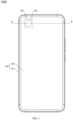
- FIG. 2 is a schematic cross-sectional view of a partial structure of the electronic device 1000 shown in FIG. 1 that is cut along A-A according to some embodiments.
- the device housing 200 may include a frame 201 and a rear cover 202.
- the rear cover 202 is fastened to the frame 201.
- the rear cover 202 may be fastened to the frame 201 through bonding, clamping, or the like.
- the rear cover 202 and the frame 201 may alternatively be of an integrated structure. In other words, the rear cover 202 and the frame 201 are of a whole structure.
- the screen 300 may be located on a side, away from the rear cover 202, of the frame 201. In this case, the screen 300 and the rear cover 202 may be located on two sides of the frame 201 respectively.
- the screen 300, the frame 201, and the rear cover 202 together enclose an inside of the electronic device 1000.
- the inside of the electronic device 1000 may be used for placing a component, for example, a battery, a receiver, or a microphone, of the electronic device 1000.
- the screen 300 may be a flat screen or a curved screen.
- the camera module 100 may be located in the electronic device 1000.
- the camera module 100 may be located on a side, facing the rear cover 202, of the screen 300.
- the rear cover 202 may be provided with a light transmission hole 203.
- a shape of the light transmission hole 203 is not limited to a circular shape shown in FIG. 1 .
- the light transmission hole 203 is used for communication between the inside of the electronic device 1000 and an outside of the electronic device 1000. Light outside the electronic device 1000 may enter the electronic device 1000 through the light transmission hole 203.
- the camera module 100 may capture the light that enters the electronic device 1000.
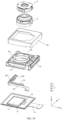
- FIG. 3 is a diagram of a structure of the camera module 100 shown in FIG. 1 according to some embodiments.
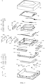
- FIG. 4 is a partial schematic exploded view of the camera module 100 shown in FIG. 3 according to some embodiments.
- the camera module 100 may include a motor 1, a lens 2, a variable-aperture stop 3, a module circuit board 4, an image sensor 5, a filter bracket 6, and a filter 7. It can be understood that the image sensor 5 is also referred to as a photosensitive chip or a photosensitive element.
- the image sensor 5 is configured to capture ambient light, and convert image information carried in the ambient light into an electrical signal.
- the camera module 100 is defined to have a first direction X, a second direction Y, and a third direction Z.
- the first direction X may be a width direction of the camera module 100.
- the second direction Y may be a length direction of the camera module 100, and the second direction Y is perpendicular to the first direction X.
- the third direction Z may be a height direction of the camera module 100, and the third direction Z is perpendicular to the first direction X and the second direction Y.
- a coordinate system of the camera module 100 may be flexibly set according to a specific actual requirement.
- the lens 2 may be mounted to the motor 1.
- An optical-axis direction of the lens 2 is parallel to the third direction Z of the camera module 100.
- the optical-axis direction of the lens 2 and an optical-axis direction of the camera module 100 are a same direction.
- the motor 1 may control the lens 2 to move along the third direction Z, to implement autofocus (autofocus, AF).
- the motor 1 may further control the lens 2 to move along a plane (namely, an X-Y plane) perpendicular to the third direction Z.
- a plane namely, an X-Y plane
- the motor 1 may control movement of the lens 2 on the X-Y plane, to counteract a shake stroke produced by the lens 2 on the X-Y plane, and avoid or reduce a position offset of the lens 2 that is caused by the shake.
- the camera module 100 in this application may control movement of the lens 2 on the X-Y plane through the motor 1, to implement optical image stabilization (optical image stabilization, OIS) for the camera module 100, and improve imaging quality of the camera module 100.
- optical image stabilization optical image stabilization
- variable-aperture stop 3 may be located on a light entrance side of the lens 2.
- the variable-aperture stop 3 has an aperture hole 3a, and a size of the aperture hole 3a is automatically adjustable.
- Light may enter the lens 2 through the aperture hole 3a of the variable-aperture stop 3.
- the variable-aperture stop 3 is configured to adjust an amount of light entering the lens, so that the camera module 100 can maintain constant image shooting quality under a plurality of luminance conditions.
- the image sensor 5 may be fastened to the module circuit board 4 and electrically connected to the module circuit board 4.
- the image sensor 5 and the module circuit board 4 may transmit signals to each other.
- the filter bracket 6 is fastened to the module circuit board 4.
- the filter bracket 6 and the image sensor 5 are located on a same side of the module circuit board 4.
- the filter bracket 6 is provided with a light transmission hole 6a.
- the filter 7 is fastened to the filter support 6.
- the filter 7 may be located in the light transmission hole 6a.
- the filter 7 is further disposed opposite to the image sensor 5.
- the filter 7 may be configured to filter out infrared light, blue light, or the like from light before the light enters the image sensor 5, to ensure good imaging quality of the image sensor 5.
- the motor 1 is fastened to the module circuit board 4, and the motor 1 and the image sensor 5 are located on a same side of the module circuit board 4.
- the image sensor 5, the filter 7, the lens 2, and the variable-aperture stop 3 are sequentially arranged.
- the image sensor 5 is located on a light exit side of the lens 2.
- the filter 7 is located between the lens 2 and the image sensor 5.
- the motor 1 has an avoidance hole 1a.
- a part of the filter bracket 6 may pass through the avoidance hole 1a and enter the drive motor 1.
- a part of the filter bracket 6 is located in the drive motor 1. In this way, along the third direction Z, the filter bracket 6 and the drive motor 1 have an overlapping region. This can reduce the height of the camera module 100 to a large extent.
- FIG. 5 is a diagram of a structure of the motor shown in FIG. 4 according to some embodiments.
- the first image stabilization coil 131, the first image stabilization magnetic piece 132, and the first image stabilization magnetic-conductive piece 135 are disposed in correspondence with each other to form a drive mechanism.
- the second image stabilization coil 133, the second image stabilization magnetic piece 134, and the second image stabilization magnetic-conductive piece 136 are disposed in correspondence with each other to form another drive mechanism.
- the first image stabilization magnetic-attractive piece 161 and the second image stabilization magnetic-attractive piece 162 each are a part of the image stabilization magnetic-attractive piece 16 of the motor 1.
- There are a plurality of first support pieces 151 and a plurality of second support pieces 152 are a plurality of first support pieces 151 and a plurality of second support pieces 152. For example, in this embodiment, an example in which there are three first support pieces 151 and three second support pieces 152 is used for description.
- the focusing drive module 20 may include a focusing bracket 21, a focusing drive mechanism 22, a circuit board assembly 23, a focusing magnetic-attractive piece 233, and a third support piece 235.
- the focusing drive mechanism 22 may include a focusing coil 221 and a focusing magnetic piece 222.
- the focusing drive mechanism 22 may further include a focusing magnetic-conductive piece 223.
- the circuit board assembly 23 includes a focusing circuit board 231, a focusing drive chip 232, a focusing sensor 234, and a reinforcing piece 236.
- the circuit board assembly 23 may alternatively not include the focusing sensor 234 and/or the reinforcing piece 236.
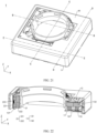
- FIG. 6 is a diagram of a structure of the base 11 shown in FIG. 5 according to some embodiments.
- the base 11 may include a bottom plate 111 and a side frame 112, and the side frame 112 is connected to a periphery of the bottom plate 111.
- the bottom plate 111 may be approximately frame-shaped. To be specific, a through hole is provided in the middle of the bottom plate 111.
- the bottom plate 111 may include a first corner region 111a, a first edge region 111b, a second corner region 111c, a second edge region 111d, and a third corner region 111e that are sequentially connected, and the first edge region 111b and the second edge region 111d are arranged at an included angle.
- the bottom plate 111 may further include a third edge region 111f and a fourth edge region 111g.
- the third edge region 111f is connected to the third corner region 111e and is disposed opposite to the first edge region 111b.
- the fourth edge region 111g is connected to the first corner region 111a and is disposed opposite to the second edge region 111d.
- a width of the first edge region 111b and a width of the second edge region 111d are greater than a width of the third edge region 111f and a width of the fourth edge region 111g.
- the bottom plate 111 may have an upper surface, and the upper surface of the bottom plate 111 is arranged facing the side frame 112.
- the bottom plate 111 may be provided with a plurality of first grooves 1111.
- the first groove 1111 may be recessed from the upper surface of the bottom plate 111 to an inside of the bottom plate 111, and an extension direction of the first groove 1111 is parallel to the second direction Y.
- the bottom plate 111 may include a plurality of first stopper groups.
- the plurality of first stopper groups are disposed in a one-to-one correspondence with the plurality of first grooves 1111.
- Each first stopper group includes two first stoppers 1112 that protrude from the upper surface of the bottom plate 111.
- the two first stoppers 1112 are respectively located at two ends of a corresponding first groove 1111.
- an arrangement direction of the two first stoppers 1112 may be parallel to the extension direction of the first groove 1111.
- the bottom plate 111 may further include a plurality of first positioning posts 1113 and a plurality of second positioning posts 1114.
- the plurality of first positioning posts 1113 are located in the first edge region 111b of the bottom plate 111.
- the plurality of first positioning posts 1113 may be spaced apart and protrude relative to the upper surface of the bottom plate 111.
- the plurality of second positioning posts 1114 are located in the second edge region 111d of the bottom plate 111.
- the plurality of second positioning posts 1114 may be spaced apart and protrude relative to the upper surface of the bottom plate 111.
- the base 11 may include an insulation body and a conductor.
- the conductor is embedded in the insulation body, and may form a plurality of transmission channels to implement signal transmission.
- the insulation body may form bodies of the bottom plate 111 and the side frame 112.
- the conductor may be arranged in the bottom plate 111 and the side frame 112. For example, a part of terminals of the conductor may be exposed from an outer periphery of the bottom plate 111, a part of terminals of the conductor may be exposed from the upper surface of the bottom plate 111, and a part of terminals of the conductor may be exposed from an upper surface of the side frame 112.
- the base 11 may include a first solder pad 11151 and a second solder pad 11152.
- the first solder pad 11151 may be formed by a part of terminals of the conductor.
- the second solder pad 11152 may be formed by another part of terminals of the conductor.
- the first solder pad 11151 is located in the first edge region 111b of the bottom plate 111 and is exposed relative to the upper surface of the bottom plate 111.
- the first solder pad 11151 may be located between two adjacent first positioning posts 1113.
- the second solder pad 11152 is located in the second edge region 111d of the bottom plate 111 and is exposed relative to the upper surface of the bottom plate 111.
- the second solder pad 11152 may be located between two adjacent second positioning posts 1114.
- the side frame 112 may have first avoidance space 1121 and second avoidance space 1122, the first avoidance space 1121 is arranged in correspondence with the first edge region 111b of the bottom plate 111, and the second avoidance space 1122 is arranged in correspondence with the second edge region 111d of the bottom plate 111.
- FIG. 7 is a first diagram of a partial structure of the motor 1 shown in FIG. 4 .
- the first support piece 151 may be arranged in a sliding shaft structure, for example, a cylindrical structure.
- a sliding shaft structure for example, a cylindrical structure.
- an axial direction of the sliding shaft is parallel to the extension direction of the first groove 1111.
- the first support piece 151 may be arranged in a ball structure.
- the first support piece 151 may include a plurality of balls.
- an arrangement direction of the plurality of balls is parallel to the extension direction of the first groove 1111.
- the plurality of first support pieces 151 may be all in a sliding shaft structure or a ball structure, or in a combined sliding shaft and ball structure. This is not strictly limited in this embodiment of this application.
- the plurality of first support pieces 151 may include at least one of a sliding shaft or a ball.
- the plurality of first support pieces 151 and the base 11 may alternatively form an integrated mechanical part. Details are not described herein.
- the first image stabilization magnetic-attractive piece 161 may be approximately in a rectangular shape, a long edge of the first image stabilization magnetic-attractive piece 161 may be parallel to or approximately parallel to the first direction X, and a short edge of the first image stabilization magnetic-attractive piece 161 may be parallel to or approximately parallel to the second direction Y.
- the first image stabilization magnetic-attractive piece 161 may be made of a material that can generate a magnetic attraction force with a magnet or another magnetic component, for example, a ferromagnetic material.
- the second image stabilization magnetic-attractive piece 162 may be mounted in the second recessed groove 1117, to be fastened to the base 11.
- the second image stabilization magnetic-attractive piece 162 may be bonded to a bottom wall of the second recessed groove 1117.
- a size of the second image stabilization magnetic-attractive piece 162 along the second direction Y may be greater than a size of the second image stabilization magnetic-attractive piece 162 along the first direction X.
- the second image stabilization magnetic-attractive piece 162 may be approximately in a rectangular shape, a long edge of the second image stabilization magnetic-attractive piece 162 may be parallel to or approximately parallel to the second direction Y, and a short edge of the second image stabilization magnetic-attractive piece 162 may be parallel to or approximately parallel to the first direction X.
- the second image stabilization magnetic-attractive piece 162 may be made of a material that can generate a magnetic attraction force with a magnet or another magnetic component, for example, a ferromagnetic material.
- the size of the first image stabilization magnetic-attractive piece 161 along the first direction X may alternatively be less than or equal to the size of the first image stabilization magnetic-attractive piece 161 along the second direction Y
- the size of the second image stabilization magnetic-attractive piece 162 along the second direction Y may alternatively be less than or equal to the size of the second image stabilization magnetic-attractive piece 162 along the first direction X
- the first image stabilization magnetic-attractive piece 161 and the second image stabilization magnetic-attractive piece 162 may alternatively be in other shapes. This is not strictly limited in this embodiment of this application.
- the second image stabilization coil 133 may be disposed around the plurality of second positioning posts 1114, and the plurality of second positioning posts 1114 are configured to limit a position of the second image stabilization coil 133.
- the second image stabilization magnetic-attractive piece 162 is located on a side, close to the bottom plate 111, of the second image stabilization coil 133.
- Each second stopper group includes two second stoppers 147 that are disposed in a protruding manner.
- the two second stoppers 147 are respectively located at two ends of a corresponding second groove 146.
- an arrangement direction of the two second stoppers 147 may be parallel to the extension direction of the second groove 146.
- the second connection portion 144 is disposed away from space that is exactly between the second support portion 143 and the third support portion 145, and the second support portion 143, the second connection portion 144, and the third support portion 145 may approximately form a "U" shape.
- FIG. 10 is a diagram of a partial structure of the guide bracket 14 shown in FIG. 9 .
- the guide bracket 14 includes a body and a reinforcing piece embedded in the body. Strength of the reinforcing piece is greater than strength of the body, to increase overall structural strength of the guide bracket 14.
- the body may be made of a plastic material, and the reinforcing piece may be made of a metal material.
- the first connection portion 142 includes a first body 142a and a first reinforcing piece 142b embedded in the first body 142a, and strength of the first reinforcing piece 142b is greater than strength of the first body 142a.
- the first body 142a may be approximately plate-shaped, and a size of the first body 142a along the third direction Z is greater than a size of the first body 142a along the first direction X. In this case, the first body 142a approximately stands upright on a Y-Z plane.
- the first reinforcing piece 142b may be approximately plate-shaped, and a size of the first reinforcing piece 142b along the third direction Z is less than a size of the first reinforcing piece 142b along the first direction X. In this case, the first reinforcing piece 142b is approximately laid on the X-Y plane. In this embodiment, the first reinforcing piece 142b can increase strength of the first connection portion 142, so that relative positions of the first support portion 141 and the second support portion 143 are more stable. In addition, a plane on which the first reinforcing piece 142b is laid intersects with, or is even approximately perpendicular to, a plane on which the first body 142a stands upright. Therefore, the first reinforcing piece 142b significantly increases strength of the first connection portion 142.
- the second connection portion 144 may include a second body 144a and a second reinforcing piece 144b embedded in the second body 144a, and strength of the second reinforcing piece 144b is greater than strength of the second body 144a.
- the second body 144a may be approximately plate-shaped, and a size of the second body 144a along the third direction Z is greater than a size of the second body 144a along the second direction Y. In this case, the second body 144a approximately stands upright on an X-Z plane.
- the second reinforcing piece 144b may be approximately plate-shaped, and a size of the second reinforcing piece 144b along the third direction Z is less than a size of the first reinforcing piece 142b along the second direction Y.
- the first reinforcing piece 142b is approximately laid on the X-Y plane.
- the second reinforcing piece 144b can increase strength of the second connection portion 144, so that relative positions of the second support portion 143 and the third support portion 145 are more stable.
- a plane on which the second reinforcing piece 144b is laid intersects with, or is even approximately perpendicular to, a plane on which the second body 144a stands upright. Therefore, the second reinforcing piece 144b significantly increases strength of the second connection portion 144.
- the reinforcing piece may further include a third reinforcing piece 141b, a fourth reinforcing piece 143b, and a fifth reinforcing piece 145b.
- the fourth reinforcing piece 143b connects the first reinforcing piece 142b to the second reinforcing piece 144b.
- the fourth reinforcing piece 143b may be located in the second support portion 143.
- the third reinforcing piece 141b is connected to an end, away from the second reinforcing piece 144b, of the first reinforcing piece 142b.
- the third reinforcing piece 141b may be located in the first support portion 141.
- the fifth reinforcing piece 145b is connected to an end, away from the second reinforcing piece 144b, of the second reinforcing piece 144b.
- the fifth reinforcing piece 145b may be located in the third support portion 145.
- the third reinforcing piece 141b, the first reinforcing piece 142b, the fourth reinforcing piece 143b, the second reinforcing piece 144b, and the fifth reinforcing piece 145b are sequentially connected, and the reinforcing piece is of an integrated structure.
- the reinforcing piece may be formed by bending or stamping an integrated metal piece.
- first reinforcing piece 142b and the second reinforcing piece 144b may alternatively not be connected to each other, and are independent of each other.
- the first reinforcing piece 142b may stand upright on the Y-Z plane, and the second reinforcing piece 144b may stand upright on the X-Z plane.
- a specific structure of the reinforcing piece is not strictly limited in this embodiment of this application.
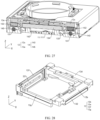
- FIG. 11 is a second diagram of a partial structure of the motor 1 shown in FIG. 4 .
- the guide bracket 14 is mounted to the base 11.
- the first support portion 141 is disposed in correspondence with the first corner region 111a of the bottom plate 111.
- the second support portion 143 is disposed in correspondence with the second corner region 111c of the bottom plate 111.
- the third support portion 145 is disposed in correspondence with the third corner region 111e of the bottom plate 111.
- the three first sliding grooves 148 of the guide bracket 14 are arranged in a one-to-one correspondence with the three first grooves 1111 of the base 11.
- the first support piece 151 mounted in the first groove 1111 is partially embedded in the first sliding groove 148.
- the guide bracket 14 When the first support piece 151 is in the sliding shaft structure, the guide bracket 14 is in line contact with the first support piece 151 during relative movement, so that a risk of a dent caused by excessively large impact pressure can be avoided, and reliability is improved.
- a width of a contact position between the first support piece 151 and the guide bracket 14 may be increased to further improve reliability of structural fitting.
- guiding directions of the plurality of first support pieces 151 are parallel to the second direction Y. Therefore, the guide bracket 14 may slide relative to the base 11 along the second direction Y.
- the first support piece 151 may also limit positions of other mechanical parts along a direction perpendicular to the guiding direction of the first support piece 151.
- the first support piece 151 is disposed, so that the guide bracket 14 and the base 11 limit positions of each other along the first direction X.
- the first connection portion 142 is disposed in correspondence with the first edge region 111b of the bottom plate 111, and the first connection portion 142 may be located on a side, away from the third edge region 111f of the bottom plate 111, of the first image stabilization coil 131.
- the first connection portion 142 may be at least partially located in the first avoidance space 1121 of the side frame 112 of the base 11, to improve space utilization of the motor 1.
- the second connection portion 144 is disposed in correspondence with the second edge region 111d of the bottom plate 111, and the second connection portion 144 may be located on a side, away from the fourth edge region 111g of the bottom plate 111, of the second image stabilization coil 133.
- the second connection portion 144 may be at least partially located in the second avoidance space 1122 of the side frame 112 of the base 11, to improve space utilization of the motor 1.
- fitting between the first connection portion 142 and the side frame 112 and between the second connection portion 144 and the side frame 112 may further meet a requirement for movable avoidance and/or a requirement for position limiting.
- the guide bracket 14 and the base 11 can slide relative to each other along the second direction Y, and space that allows the first connection portion 142 to move is reserved between the first connection portion 142 and the side frame 112, to implement movable avoidance.
- the guide bracket 14 and the base 11 can limit positions of each other along the first direction X, and the second connection portion 144 and the side frame 112 may form a position-limiting structure, for example, a fitting structure between the second connection portion 144 and a wall surface of the second avoidance space 1122.
- the guide bracket 14 and the base 11 may alternatively implement position limiting along the first direction X by using another structure. This is not strictly limited in this embodiment of this application.
- the plurality of second support pieces 152 may be mounted in the plurality of second grooves 146 of the guide bracket 14 in a one-to-one correspondence.
- the three second support pieces 152 are mounted to the first support portion 141, the second support portion 143, and the third support portion 145 of the guide bracket 14 respectively.
- a part of an outer surface of the second support piece 152 protrudes relative to a surface of a corresponding support portion of the guide bracket 14.
- the second support piece 152 is located between two corresponding second stoppers 147, and the two second stoppers 147 are configured to limit a position of the second support piece 152.
- the second support piece 152 may alternatively be fastened to the guide bracket 14 through glue dispensing, welding, or the like.
- the plurality of second support pieces 152 and the guide bracket 14 may alternatively form an integrated mechanical part. Details are not described herein.
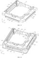
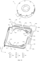
- FIG. 12 is a diagram of a structure of the image stabilization bracket 12 shown in FIG. 5 .
- FIG. 13 is a diagram of a structure of the image stabilization bracket 12 shown in FIG. 12 at another angle.
- the image stabilization bracket 12 may be approximately frame-shaped.
- the image stabilization bracket 12 may include a first corner portion 12a, a first edge portion 12b, a second corner portion 12c, a second edge portion 12d, and a third corner portion 12e that are sequentially connected, and the first edge portion 12b and the second edge portion 12d are arranged at an included angle.
- the image stabilization bracket 12 further includes a third edge portion 12f and a fourth edge portion 12g.
- the third edge portion 12f is connected to the third corner portion 12e and is disposed opposite to the first edge portion 12b.
- the fourth edge portion 12g is connected to the first corner portion 12a and is disposed opposite to the second edge portion 12d.
- first edge portion 12b and the second edge portion 12d may be arranged to be perpendicular to each other, the third edge portion 12f may be parallel to the first edge portion 12b, and the fourth edge portion 12g may be parallel to the second edge portion 12d.
- first edge portion 12b and the second edge portion 12d may be directly connected or may be indirectly connected through the second corner portion 12c
- the second corner portion 12c is connected to the first edge portion 12b and/or the second edge portion 12d
- the second edge portion 12d and the third edge portion 12f may be directly connected or may be indirectly connected through the third corner portion 12e
- the third corner portion 12e is connected to the first edge portion 12b and/or the second edge portion 12d
- the fourth edge portion 12g and the first edge portion 12b may be directly connected or may be indirectly connected through the first corner portion 12a
- the first corner portion 12a is connected to the first edge portion 12b and/or the second edge portion 12d
- the third edge portion 12f and the fourth edge portion 12g may be directly connected or may be connected through a corner portion.
- a specific structure of the image stabilization bracket 12 is not strictly limited in this embodiment of this application.
- the image stabilization bracket 12 may be provided with a plurality of second sliding grooves 121, and the plurality of second sliding grooves 121 are disposed facing a same side of the image stabilization bracket 12.
- the three second sliding grooves 121 are located in the first corner portion 12a, the second corner portion 12c, and the third corner portion 12e respectively.
- An extension direction of the second sliding groove 121 may be parallel to the first direction X.
- the first edge portion 12b is provided with a first mounting slot 122
- the first mounting slot 122 is located between two second sliding grooves 121
- the second edge portion 12d is provided with a second mounting slot 123
- the second mounting slot 123 is located between two second sliding grooves 121.
- the second mounting slot 123 and the first mounting slot 122 are arranged facing a same side of the image stabilization bracket 12.
- the image stabilization bracket 12 has movement space 124, and the movement space 124 is located between the first edge portion 12b and the third edge portion 12f, and is located between the second edge portion 12d and the fourth edge portion 12g.
- the first edge portion 12b, the second edge portion 12d, the third edge portion 12f, and the fourth edge portion 12g are disposed around the movement space 124.
- the movement space 124 passes through the image stabilization bracket 12 along the third direction Z.
- the image stabilization bracket 12 may further include a first stop block 125.
- the first stop block 125 is located in the movement space 124 and is fastened to a plurality of edge portions of the image stabilization bracket 12.
- first stop blocks 125 There may be a plurality of first stop blocks 125, and the plurality of first stop blocks 125 may be arranged on a periphery of the movement space 124 at spacings. Alternatively, there may be one first stop block 125. This is not strictly limited in this embodiment of this application.
- the third edge portion 12f of the image stabilization bracket 12 is provided with a through hole 126, the through hole 126 passes through the third edge portion 12f along the first direction X, and the through hole 126 communicates with the movement space 124.
- the third edge portion 12f may be further provided with a third mounting slot 127 and a fourth mounting slot 128.
- the third mounting slot 127 and the fourth mounting slot 128 are spaced apart and are respectively located on two sides of the through hole 126. Extension directions of the third mounting slot 127 and the fourth mounting slot 128 may be parallel to the third direction Z.
- FIG. 14 is a diagram of an assembly structure of the circuit board assembly 23 shown in FIG. 5 .
- FIG. 17 is a diagram of a structure of the focusing bracket 21 shown in FIG. 5 .
- the focusing bracket 21 is slidably connected to the image stabilization bracket 12 through the third support piece 235, and a relative sliding direction of the focusing bracket 21 and the image stabilization bracket 12 is parallel to a guiding direction of the third support piece 235, namely, the third direction Z.
- a sliding direction of the sliding shaft is the guiding direction of the third support piece 235.
- an arrangement direction of a plurality of balls is the guiding direction of the third support piece 235.
- a distance between the center axis of the focusing bracket 21 and an outer side surface of the fourth edge portion 12g of the image stabilization bracket 12 may alternatively be greater than or equal to a distance between the center axis of the focusing bracket 21 and an outer side surface of the third edge portion 12f of the image stabilization bracket 12.
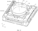
- FIG. 20 is a seventh diagram of a partial structure of the motor 1 shown in FIG. 4 .
- the plurality of first spring plates 18 may be arranged on a plane perpendicular to the third direction Z, and are located on a side, backing the bottom plate 111, of the image stabilization bracket 12.
- the plurality of first spring plates 18 may be arranged on the X-Y plane. A part of the first spring plates 18 connect the first edge portion 12b to the side frame 112 of the base 11, and the other part of the first spring plates 18 connect the second edge portion 12d to the side frame 112 of the base 11.
- the plurality of first spring plates 18 may be arranged in space above the first edge portion 12b and the second edge portion 12d of the image stabilization bracket 12, to improve space utilization of the motor 1.
- the plurality of first spring plates 18 are configured to: when the image stabilization bracket 12 moves relative to the base 11 and leaves a balanced position, provide an elastic force to make the image stabilization bracket 12 move back to the balanced position.
- the first spring plate 18 may be made of a conductive material, to provide a signal transmission function.
- the position-limiting bracket 30 is fastened to a side, backing the bottom plate 111, of the image stabilization bracket 12.
- the position-limiting bracket 30 includes a second stop block 301, and the second stop block 301 is disposed directly facing the focusing bracket 21.
- the first stop block 125 of the image stabilization bracket 12 may cooperate with the second stop block 301 of the position-limiting bracket 30 to limit a movement stroke of the focusing bracket 21 along the third direction Z, to prevent the focusing bracket 21 from being detached from the position-limiting bracket 30, so that relative movement actions of the focusing bracket 21 and the position-limiting bracket 30 are more reliable.
- FIG. 21 is a diagram of a structure of the motor 1 shown in FIG. 4 at another angle.
- the housing 40 and the base 11 are assembled and matched, and the housing 40 covers the base 11.
- the housing 40 may cover the side frame 112 of the base 11 (refer to FIG. 20 ).
- the housing 40 and the base 11 cooperate to jointly package and protect an internal structure of the motor 1.
- the housing 40 is provided with a via, and a partial structure of the motor 1 is exposed from the via, for example, a partial structure of the focusing bracket 21 is exposed.
- FIG. 22 is a schematic cross-sectional view of a structure of the motor 1 shown in FIG. 21 that is cut along B-B.
- the focusing coil 221 is fastened to the image stabilization bracket 12, the focusing magnetic piece 222 is fastened to the focusing bracket 21, and the focusing coil 221 is disposed facing the focusing magnetic piece 222 and is configured to drive the focusing bracket 21 to move relative to the image stabilization bracket 12 along the third direction Z.
- the focusing bracket 21 may drive the lens 2 mounted on the focusing bracket 21 to move along the third direction Z.
- the motor 1 can implement autofocus for the camera module 100. That the focusing coil 221 is disposed facing the focusing magnetic piece 222 means that a winding plane of the focusing coil 221 faces the focusing magnetic piece 222.
- the focusing sensor 234 (refer to FIG. 14 ) fastened to the focusing circuit board 231 may be configured to detect a position change of the focusing bracket 21 along the third direction Z.
- a movement direction of the focusing bracket 21 is perpendicular to a magnetic gap between the focusing magnetic piece 222 and the focusing coil 221, and the magnetic gap is not affected by a movement action of the focusing bracket 21. Therefore, a problem that a driving force rapidly decreases due to an increase in the magnetic gap can be avoided, to ensure that a focusing driving force of the motor 1 is large and the driving force is stable. This facilitates a large-stroke design for a focusing function of the motor 1.
- the focusing magnetic piece 222 may have two opposite polarity directions, and the polarity directions of the focusing magnetic piece 222 are arranged to be perpendicular to the winding plane of the focusing coil 221. Coils in two regions of the focusing coil 221 may be disposed in correspondence with the two polarity directions of the focusing magnetic piece 222 respectively. Current flow directions in the coils in the two regions are opposite to each other. It can be understood that a polarity direction may be a direction from a north pole (N) to a south pole (S), or a direction from a south pole (S) to a north pole (N).
- a side, facing the focusing coil 221, of the focusing magnetic piece 222 includes a north pole (N) and a south pole (S); and a side, backing the focusing coil 221, of the focusing magnetic piece 222 includes a south pole (S) and a north pole (N) correspondingly.
- the focusing magnetic piece 222 may include one or more magnets, and the focusing magnetic piece 222 may be implemented in a plurality of structures.
- a dual-magnet solution may be used for the focusing magnetic piece 222.
- the focusing magnetic piece 222 includes two magnets, and the two magnets are arranged along the third direction Z and have opposite polarity directions.
- the focusing magnetic piece 222 is a Halbach magnet array.
- a single-magnet solution may be used for the focusing magnetic piece 222.
- the focusing magnetic piece 222 includes one magnet, and the magnet includes two parts with opposite polarity directions. The magnet may be made by using a bipolar magnetization technique.
- a magnetic attraction force is formed between the focusing magnetic piece 222 and the focusing magnetic-conductive piece 223, so that the focusing bracket 21 trends to approach the third edge portion 12f of the image stabilization bracket 12, the focusing bracket 21, the third support piece 235, and the image stabilization bracket 12 keep in contact, and the third support piece 235 can better guide the focusing bracket 21 to move relative to the image stabilization bracket 12 along the third direction Z.
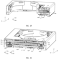
- FIG. 23 is a diagram of a partial structure of the structure shown in FIG. 22 .
- the first image stabilization magnetic piece 132 is fastened to the image stabilization bracket 12, the first image stabilization coil 131 is fastened to the base 11, the first image stabilization coil 131 is disposed facing the first image stabilization magnetic piece 132 and is configured to drive the image stabilization bracket 12 to move relative to the base 11 along the first direction X, and the first image stabilization magnetic piece 132 and the first image stabilization coil 131 are arranged along the third direction Z. That the first image stabilization coil 131 is disposed facing the first image stabilization magnetic piece 132 means that a winding plane of the first image stabilization coil 131 faces the first image stabilization magnetic piece 132.
- the winding plane of the first image stabilization coil 131 may be arranged to be parallel to the X-Y plane.
- the first image stabilization sensor 171 (refer to FIG. 7 ) fastened to the bottom plate 111 of the base 11 may be configured to detect a position change of the image stabilization bracket 12 along the first direction X.
- the first image stabilization magnetic piece 132 may have two opposite polarity directions (as indicated by arrows in FIG. 23 ), and the polarity directions of the first image stabilization magnetic piece 132 are arranged to be perpendicular to the winding plane of the first image stabilization coil 131. Coils in two regions of the first image stabilization coil 131 may be disposed in correspondence with the two polarity directions of the first image stabilization magnetic piece 132 respectively. Current flow directions in the coils in the two regions are opposite to each other.
- a side, facing the first image stabilization coil 131, of the first image stabilization magnetic piece 132 includes a north pole (N) and a south pole (S).
- a side, backing the focusing coil 221, of the first image stabilization magnetic piece 132 includes a south pole (S) and a north pole (N) correspondingly.
- the first image stabilization magnetic piece 132 may include one or more magnets, and the first image stabilization magnetic piece 132 may be implemented in a plurality of structures.
- a dual-magnet structure may be used for the first image stabilization magnetic piece 132.
- the first image stabilization magnetic piece 132 includes two magnets, and the two magnets are arranged along the first direction X and have opposite polarity directions.
- FIG. 24 is a diagram of a structure of the first image stabilization magnetic piece 132 shown in FIG. 22 according to some embodiments.
- the first image stabilization magnetic piece 132 is a Halbach magnet array.
- FIG. 25 is a schematic cross-sectional view of a structure of the motor 1 shown in FIG. 21 that is cut along C-C.
- the second image stabilization magnetic piece 134 is fastened to the image stabilization bracket 12, the second image stabilization coil 133 is fastened to the base 11, the second image stabilization coil 133 is disposed facing the second image stabilization magnetic piece 134 and is configured to drive the image stabilization bracket 12 to move relative to the base 11 along the second direction Y, and the second image stabilization magnetic piece 134 and the second image stabilization coil 133 are arranged along the third direction Z. That the second image stabilization coil 133 is disposed facing the second image stabilization magnetic piece 134 means that a winding plane of the second image stabilization coil 133 faces the second image stabilization magnetic piece 134.
- the winding plane of the second image stabilization coil 133 may be arranged to be parallel to the X-Y plane.
- the second image stabilization sensor 172 (refer to FIG. 7 ) fastened to the bottom plate 111 of the base 11 may be configured to detect a position change of the image stabilization bracket 12 along the second direction Y.
- a movement direction of the image stabilization bracket 12 is perpendicular to a magnetic gap between the second image stabilization magnetic piece 134 and the second image stabilization coil 133, and the magnetic gap is not affected by a movement action of the image stabilization bracket 12. Therefore, a problem that a driving force rapidly decreases due to an increase in the magnetic gap can be avoided, to ensure that an image stabilization driving force of the motor 1 is large and the driving force is stable. This facilitates a large-stroke design for an optical image stabilization function of the motor 1.
- the image stabilization bracket 12 can drive the focusing bracket 21 and the lens 2 to move relative to the base 11 along the first direction X and/or the second direction Y, to implement movement on the X-Y plane.
- the motor 1 can implement optical image stabilization for the camera module 100.
- the motor 1 can implement a large-stroke design for optical image stabilization, to achieve better image shooting experience.
- a direction in which the first image stabilization coil 131 and the first image stabilization magnetic piece 132 drive the image stabilization bracket 12 to move is perpendicular to a direction in which the second image stabilization coil 133 and the second image stabilization magnetic piece 134 drive the image stabilization bracket 12 to move.
- a direction in which the first image stabilization coil 131 and the first image stabilization magnetic piece 132 drive the image stabilization bracket 12 to move may alternatively intersect with but is not perpendicular to a direction in which the second image stabilization coil 133 and the second image stabilization magnetic piece 134 drive the image stabilization bracket 12 to move.
- the second image stabilization magnetic piece 134 may have two opposite polarity directions, and the polarity directions of the second image stabilization magnetic piece 134 are perpendicular to the winding plane of the second image stabilization coil 133. Coils in two regions of the second image stabilization coil 133 may be disposed in correspondence with the two polarity directions of the second image stabilization magnetic piece 134 respectively. Current flow directions in the coils in the two regions are opposite to each other.
- a side, facing the second image stabilization coil 133, of the second image stabilization magnetic piece 134 includes a north pole (N) and a south pole (S).
- a side, backing the focusing coil 221, of the second image stabilization magnetic piece 134 includes a south pole (S) and a north pole (N) correspondingly.
- the focusing bracket 21 moves along with the image stabilization bracket 12, relative positions of the focusing bracket 21 and the image stabilization bracket 12 are not affected, and a width of a magnetic gap of the focusing drive mechanism 22 does not change. Therefore, the focusing drive mechanism 22 and the image stabilization drive mechanism 13 of the motor 1 are decoupled from each other, and do not interfere with each other during movement. This helps ensure driving precision of the motor 1.
- the focusing bracket 21 needs to drive the lens 2 and the variable-aperture stop 3 to move along the third direction Z.
- the image stabilization bracket 12 may be omitted from a mover during focusing.
- a weight of a mover including the focusing bracket 21, the lens 2, and the variable-aperture stop 3 is light. This facilitates miniaturization of the focusing drive mechanism 22.
- lightweight and miniaturization of the motor 1 can be implemented.
- a distance from a connection position between the focusing bracket 21 and the image stabilization bracket 12 to a center of gravity of the mover including the focusing bracket 21, the lens 2, and the variable-aperture stop 3 is short. This helps reduce a risk of overturning of the mover.
- a double-layer bracket design with the guide bracket 14 and the image stabilization bracket 12 is used for the motor 1.
- Each layer of bracket cooperates with a support piece and an adjacent mechanical part to implement guiding along one direction. No crosstalk occurs between guiding along two directions. This helps implement precise guiding for optical image stabilization.
- the guide bracket 14 and the image stabilization bracket 12 can move together relative to the base 11 along the second direction Y.
- the image stabilization bracket 12 can move relative to the guide bracket 14 along the first direction X.
- the first image stabilization magnetic-attractive piece 161 is fastened to the bottom plate 111 of the base, for example, may be located on a side, backing the first image stabilization magnetic piece 132, of the first image stabilization coil 131.
- the first image stabilization magnetic-attractive piece 161 is disposed facing the first image stabilization magnetic piece 132.
- a magnetic force between the first image stabilization magnetic-attractive piece 161 and the first image stabilization magnetic piece 132 makes the image stabilization bracket 12 tend to approach the bottom plate 111 of the base 11. As shown in FIG. 25 and FIG.
- the second image stabilization magnetic-attractive piece 162 is fastened to the bottom plate 111 of the base, for example, may be located on a side, backing the second image stabilization magnetic piece 134, of the second image stabilization coil 133.
- the second image stabilization magnetic-attractive piece 162 is disposed facing the second image stabilization magnetic piece 134. A magnetic force between the second image stabilization magnetic-attractive piece 162 and the second image stabilization magnetic piece 134 makes the image stabilization bracket 12 tend to approach the bottom plate 111 of the base 11.
- the magnetic force between the first image stabilization magnetic-attractive piece 161 and the first image stabilization magnetic piece 132 and the magnetic force between the second image stabilization magnetic-attractive piece 162 and the second image stabilization magnetic piece 134 make the image stabilization bracket 12 tend to approach the bottom plate 111 of the base 11. This ensures that the base 11, the second support piece 152, the guide bracket 14, the first support piece 151, and the image stabilization bracket 12 keep in contact, and implements pre-tightening.
- the first image stabilization magnetic-attractive piece 161 is disposed directly facing the first image stabilization magnetic piece 132, and a size of the first image stabilization magnetic-attractive piece 161 along the first direction X is greater than a size of the first image stabilization magnetic piece 132 along the first direction X.
- the first image stabilization magnetic-attractive piece 161 protrudes relative to two sides of the first image stabilization magnetic piece 132 along the first direction X.
- the first image stabilization magnetic piece 132 and the first image stabilization magnetic piece 132 can still be in a direct-facing relationship or an approximate direct-facing relationship, to ensure stability of a magnetic attraction force.
- the second image stabilization magnetic-attractive piece 162 directly faces the second image stabilization magnetic piece 134, and a size of the second image stabilization magnetic-attractive piece 162 is greater than a size of the second image stabilization magnetic piece 134.
- the second image stabilization magnetic-attractive piece 162 protrudes relative to two sides of the second image stabilization magnetic piece 134 along the second direction Y.
- the second image stabilization magnetic piece 134 and the second image stabilization magnetic piece 134 can still be in a direct-facing relationship or an approximate direct-facing relationship, to ensure stability of a magnetic attraction force.
- a projection of the second image stabilization magnetic-attractive piece 162 on the X-Y plane covers a projection of the second image stabilization magnetic piece 134 on the X-Y plane along the second direction Y, it can be considered that the second image stabilization magnetic-attractive piece 162 and the second image stabilization magnetic piece 134 are in a direct-facing relationship.
- the first image stabilization magnetic-attractive piece 161 is located between the first support portion 141 and the second support portion 143
- the second image stabilization magnetic-attractive piece 162 is located between the second support portion 143 and the third support portion 145. Therefore, the magnetic force between the first image stabilization magnetic-attractive piece 161 and the first image stabilization magnetic piece 132 and the magnetic force between the second image stabilization magnetic-attractive piece 162 and the second image stabilization magnetic piece 134 can better ensure that the three support portions (141, 143, and 145) of the guide bracket 14 are connected to the base 11 and the image stabilization bracket 12 through the support pieces. This improves reliability of an optical image stabilization process of the motor 1.
- a center distance between the first image stabilization magnetic-attractive piece 161 and the first corner portion 12a is less than a center distance between the first image stabilization magnetic-attractive piece 161 and the second corner portion 12c.
- a center distance between the second image stabilization magnetic-attractive piece 162 and the third corner portion 12e is less than a center distance between the second image stabilization magnetic-attractive piece 162 and the second corner portion 12c.
- the position arrangement of the first image stabilization magnetic-attractive piece 161 and the second image stabilization magnetic-attractive piece 162 can make pre-tightening forces between the three support portions (141, 143, and 145) of the guide bracket 14 and the base 11 and between the three support portions (141, 143, and 145) of the guide bracket 14 and the image stabilization bracket 12 more balanced and reliable.
- first image stabilization magnetic-attractive piece 161 and the second image stabilization magnetic-attractive piece 162 may alternatively be adjusted. This is not strictly limited in this embodiment of this application.
- fitting between the plurality of first support pieces 151 and the guide bracket 14 includes tight fitting and loose fitting, to reduce assembly difficulty.
- the plurality of first sliding grooves 148 of the guide bracket 14 include at least one "V"-shaped groove and at least one "U”-shaped groove or "L”-shaped groove.
- a side wall of the first sliding groove 148 is in contact with the first support piece 151, to implement tight fitting.
- first sliding grooves 148 located in the first support portion 141 and the second support portion 143 are "V"-shaped grooves.
- a bottom wall of the first sliding groove 148 is in contact with the first support piece 151, to implement loose fitting.
- a first sliding groove 148 located in the third support portion 145 is a "U"-shaped groove.
- fitting between the plurality of second support pieces 152 and the image stabilization bracket 12 includes tight fitting and loose fitting, to reduce assembly difficulty.
- the plurality of second sliding grooves 121 of the image stabilization bracket 12 include at least one "V"-shaped groove and at least one "U”-shaped groove or "L”-shaped groove.
- a side wall of the second sliding groove 121 is in contact with the second support piece 152, to implement tight fitting.
- second sliding grooves 121 located in the second corner portion 12c and the third corner portion 12e are "V"-shaped grooves.
- a bottom wall of the second sliding groove 121 is in contact with the second support piece 152, to implement loose fitting.
- a second sliding groove 121 located in the first corner portion 12a is a "U"-shaped groove.
- FIG. 28 is a diagram of a partial structure of the motor 1 shown in FIG. 4 according to some other embodiments.
- FIG. 29 is a schematic exploded view of a structure of the structure shown in FIG. 28 .
- This embodiment may include most of the technical solutions in the foregoing embodiments. The following mainly describes differences between this embodiment and the foregoing embodiments, and most content that is the same between this embodiment and the foregoing embodiments is not described in detail again.
- first edge portion 12b, the second edge portion 12d, the third edge portion 12f, and the fourth edge portion 12g of the image stabilization bracket 12 are arranged counterclockwise, and positions of the first image stabilization magnetic piece 132, the second image stabilization magnetic piece 134, and the focusing coil 221 are correspondingly arranged clockwise.
- Other related structures in this embodiment are adaptively adjusted.
- the image stabilization magnetic piece is fastened to the bottom plate 111 of the base 11, the three support portions (141, 143, and 145) of the guide bracket 14 are located between the image stabilization bracket 12 and the bottom plate 111 of the base 11, the first support piece 151 is located between the three support portions (141, 143, and 145) of the guide bracket 14 and the bottom plate 111 of the base 11, and a lower magnetic attraction solution is used for a pre-tightening structure of the motor 1.
- an upper magnetic attraction solution may alternatively be used for a pre-tightening structure of the motor 1, and a structure of the base 11, a structure and a position of the image stabilization magnetic piece, a structure and a position of the guide bracket 14, and a structure and a position of the image stabilization bracket 12 are adjusted.
- An example is described below.
- FIG. 30 is a diagram of a partial structure of the motor 1 shown in FIG. 4 according to some other embodiments.
- FIG. 31 is a schematic exploded view of a structure of the structure shown in FIG. 30 .
- This embodiment may include most of the technical solutions in the foregoing embodiments. The following mainly describes differences between this embodiment and the foregoing embodiments, and most content that is the same between this embodiment and the foregoing embodiments is not described in detail again.
- the base 11 includes a bottom plate 111, a side frame 112, and a top plate 113.
- the top plate 113 is disposed opposite to the bottom plate 111, and the side frame 112 is connected between the bottom plate 111 and the top plate 113.
- the top plate 113, a side plate, and the top plate 113 of the base 11 are in a mutually fastened structure.
- the bottom plate 111 and the side frame 112 may be an integrated mechanical part, and the top plate 113 and the side frame 112 may form an integrated structure through assembly.
- the top plate 113 and the side frame 112 may be an integrated mechanical part, and the bottom plate 111 and the side frame 112 may form an integrated structure through assembly.
- a first image stabilization magnetic piece 132 and a second image stabilization magnetic piece 134 are fastened to an image stabilization bracket 12.
- a first image stabilization coil 131 and a second image stabilization coil 133 are fastened to the bottom plate 111.
- the first image stabilization coil 131 is disposed facing the first image stabilization magnetic piece 132.
- the second image stabilization coil 133 is disposed facing the second image stabilization magnetic piece 134.
- the image stabilization bracket 12 can move relative to the base 11 along an X-Y plane, to implement optical image stabilization.
- three corner regions of the bottom plate 111 of the base 11 may not be provided with grooves.
- the top plate 113 of the base 11 may be provided with a plurality of third sliding grooves 1131.
- the plurality of third sliding grooves 1131 may be respectively located in the three corner regions of the top plate 113.
- An extension direction of the third sliding groove 1131 may be parallel to a first direction X.
- a guide bracket 14 may be provided with a plurality of third grooves 149 and a plurality of fourth sliding grooves 1410.
- the plurality of third grooves 149 are respectively located in a first support portion 141, a second support portion 143, and a third support portion 145.
- An extension direction of the third groove 149 may be parallel to the first direction X.
- the plurality of fourth sliding grooves 1410 are arranged back to back with the plurality of third grooves 149.
- the plurality of fourth sliding grooves 1410 are respectively located in the first support portion 141, the second support portion 143, and the third support portion 145.
- An extension direction of the fourth sliding groove 1410 may be parallel to a second direction Y.
- the image stabilization bracket 12 is provided with a plurality of fourth grooves 129.
- the plurality of fourth grooves 129 may be respectively located in a first corner portion 12a, a second corner portion 12c, and a third corner portion 12e.
- An extension direction of the fourth groove 129 may be parallel to the second direction Y.
- FIG. 34 is a schematic cross-sectional view of a structure of the structure shown in FIG. 30 that is cut along F-F.
- FIG. 35 is a schematic cross-sectional view of a structure of the structure shown in FIG. 30 that is cut along G-G.
- an image stabilization drive mechanism 13 includes an image stabilization magnetic-attractive piece 16, and the image stabilization magnetic-attractive piece 16 is fastened to the top plate 113 of the base 11.
- the image stabilization bracket 12 is located on an inner side of the side frame 112, and the three support portions (141, 143, and 145) of the guide bracket 14 are located between the image stabilization bracket 12 and the top plate 113. Magnetic attraction forces between the image stabilization magnetic-attractive piece 16 and the first image stabilization magnetic piece 132 and between the image stabilization magnetic-attractive piece 16 and the second image stabilization magnetic piece 134 make the image stabilization bracket 12 tend to approach the top plate 113.
- the first support portion 141 of the guide bracket 14 is located between the first corner portion 12a of the image stabilization bracket 12 and the top plate 113.
- the second support portion 143 of the guide bracket 14 is located between the second corner portion 12c of the image stabilization bracket 12 and the top plate 113.
- the third support portion 145 of the guide bracket 14 is located between the third corner portion 12e of the image stabilization bracket 12 and the top plate 113.
- a plurality of first support pieces 151 are mounted in the plurality of third grooves 149 of the guide bracket 14 in a one-to-one correspondence.
- the plurality of third sliding grooves 1131 of the top plate 113 are arranged in a one-to-one correspondence with the plurality of third grooves 149 of the guide bracket 14.
- the first support piece 151 mounted in the third groove 149 is partially embedded in the first sliding groove 148.
- the guide bracket 14 is slidably connected to the top plate 113 through the plurality of first support pieces 151, and a relative sliding direction of the guide bracket 14 and the top plate 113 is parallel to guiding directions of the plurality of first support pieces 151.
- a plurality of second support pieces 152 are mounted in the plurality of fourth grooves 129 of the image stabilization bracket 12 in a one-to-one correspondence.
- the plurality of fourth sliding grooves 1410 of the guide bracket 14 are arranged in a one-to-one correspondence with the plurality of fourth grooves 129 of the image stabilization bracket 12.
- the second support piece 152 mounted in the fourth groove 129 is partially embedded in the fourth sliding groove 1410.
- the image stabilization bracket 12 is slidably connected to the guide bracket 14 through the plurality of second support pieces 152, and a relative sliding direction of the image stabilization bracket 12 and the guide bracket 14 is parallel to guiding directions of the
- the guiding directions of the plurality of first support pieces 151 and the guiding directions of the plurality of second support pieces 152 intersect with each other.
- the guiding directions of the plurality of first support pieces 151 may be parallel to the first direction X
- the guiding directions of the plurality of second support pieces 152 may be parallel to the second direction Y.
- the guiding directions of the plurality of first support pieces 151 and the guiding directions of the plurality of second support pieces 152 may be exchanged, and extension directions of grooves and/or sliding grooves on the top plate 113, the guide bracket 14, and the image stabilization bracket 12 are adaptively changed.
- the image stabilization bracket 12 tends to approach the top plate 113 under a magnetic force. This can ensure that the top plate 113, the plurality of first support pieces 151, the guide bracket 14, the plurality of second support pieces 152, and the image stabilization bracket 12 keep in contact, to implement precise guiding during movement of the image stabilization bracket 12 relative to the base 11, and improve reliability and precision of optical image stabilization.
- the image stabilization bracket 12 is subject to a driving force parallel to the guiding direction of the first support piece 151, the image stabilization bracket 12 and the guide bracket 14 move together relative to the base 11 along the guiding direction of the first support piece 151.
- the guide bracket 14 remains stationary relative to the base 11, and the image stabilization bracket 12 moves relative to the guide bracket 14 and the base 11 along the guiding direction of the second support piece 152.
- the top plate 113 may be L-shaped.
- the top plate 113 may include three corner regions that are spaced away from each other and two edge regions that connect the three corner regions, and the two edge regions are arranged at an included angle.
- the top plate 113 is disposed in correspondence with the guide bracket 14.
- the three corner regions of the top plate 113 are arranged in correspondence with the three support portions (141, 143, and 145) of the guide bracket 14, and the two edge regions of the top plate 113 are arranged in correspondence with two connection portions (142 and 144) of the guide bracket 14.
- the top plate 113 when the top plate 113 cooperates with another structure to implement a guiding function, the top plate 113 has a small size. This facilitates a miniaturization design of the motor 1. It can be understood that, in some other embodiments, the top plate 113 may alternatively be frame-shaped.
- a first connection portion 142 of the guide bracket 14 may be stacked between the first edge portion 12b of the image stabilization bracket 12 and the top plate 113, and a second connection portion 144 of the guide bracket 14 may be stacked between the second edge portion 12d of the image stabilization bracket 12 and the top plate 113.
- the first connection portion 142 may be located on a side, backing to movement space 124, of the first edge portion 12b
- the second connection portion 144 may be located on a side, backing the movement space 124, of the second edge portion 12d. In this way, arrangement is performed around a periphery, to reduce a height of the motor 1 and implement miniaturization.
- the image stabilization magnetic-attractive piece 16 is located on a side, backing the guide bracket 14, of the top plate 113, and the image stabilization magnetic-attractive piece 16 is an integrated mechanical part.
- a quantity of image stabilization magnetic-attractive pieces 16 is small, and assembly is convenient.
- an area of the image stabilization magnetic-attractive piece 16 is large. This can ensure a magnitude and stability of the magnetic forces between the image stabilization magnetic-attractive piece 16 and the first image stabilization magnetic piece 132 and between the image stabilization magnetic-attractive piece 16 and the second image stabilization magnetic piece 134, to improve reliability of optical image stabilization of the motor 1.
- the motor 1 further includes a plurality of first spring plates 18.
- the plurality of first spring plates 18 may be arranged on a plane parallel to a third direction Z, and located on a side, backing the first edge portion 12b or the second edge portion 12d, of the image stabilization bracket 12.
- the plurality of first spring plates 18 may be disposed close to an outer side of the third edge portion 12f or the fourth edge portion 12g of the image stabilization bracket 12.
- the plurality of first spring plates 18 connect the image stabilization bracket 12 to the bottom plate 111.
- the plurality of first spring plates 18 are arranged on an X-Z plane or a Y-Z plane, and the plurality of first spring plates 18, the base 11, and the image stabilization bracket 12 are arranged compactly. This helps reduce a height of the motor 1 and implement miniaturization of the motor 1.
- a dual-coil driving solution is used for the image stabilization drive mechanism 13 of the motor 1, so that a larger driving force can be provided. This helps improve driving efficiency and increase a stroke for optical image stabilization.
- the first sub-coil 1311 and the second sub-coil 1312 are respectively located on two sides of the first image stabilization magnetic piece 132 that back each other, accompanying forces of driving forces of the first sub-coil 1311 and the second sub-coil 1312 can counteract each other, to implement a more accurate driving action.
- the focusing bracket 21 may alternatively be connected to the first sliding shaft 235a and the second sliding shaft 235b in other manners.
- the focusing bracket 21 is provided with a first via and a second via. Then the first sliding shaft 235a and the second sliding shaft 235b are inserted in the first via and the second via respectively.
- a second flipping axis is a connection line (a line P3-P4 shown in FIG. 42 and FIG. 43 ) between a top boundary line of the first contact position M1 and a top boundary line of the third contact position N1.
- a third flipping axis is a connection line (a line P5-P6 shown in FIG. 42 and FIG. 43 ) between a right boundary line of the first contact position M1 and a right boundary line of the second contact position M2.
- a torque of the magnetic attraction force increases.
- the torque of the magnetic attraction force is equal to a product of a magnitude of the magnetic attraction force and the arm of the magnetic attraction force.
- the torque of the magnetic attraction force increases, so that a capability of the focusing bracket 21 to resist flipping caused by gravity is strengthened, and the focusing bracket 21 has better stability during movement along the third direction Z.
- a product of the magnetic attraction force and a vertical distance from the center position of the magnetic attraction force generated by the focusing magnetic-attractive piece 233 and the focusing magnetic piece 222 to the first flipping axis is greater than a gravitational torque of a focusing mover.
- the focusing mover may be a related structure, for example, the focusing bracket 21, the focusing magnetic piece 222, the lens 2, or the variable-aperture stop 3, along the third direction Z.
- a product of the magnetic attraction force and a vertical distance from the center position of the magnetic attraction force generated by the focusing magnetic-attractive piece 233 and the focusing magnetic piece 222 to the third flipping axis is greater than a gravitational torque of a focusing mover.
- FIG. 44 is a diagram of a structure of a partial structure of the motor 1 shown in FIG. 5 according to some other embodiments.
- the focusing magnetic-attractive piece 233 may include a first focusing magnetic-attractive piece 2331, a second focusing magnetic-attractive piece 2332, and a third focusing magnetic-attractive piece 2333.
- the first focusing magnetic-attractive piece 2331 includes a front surface, and a top surface and a bottom surface that are arranged backing each other. The top surface and the bottom surface may be arranged along the third direction Z, and the front surface is connected between the top surface and the bottom surface.
- the focusing circuit board 231 may be fastened to the front surface of the first focusing magnetic-attractive piece 2331.
- the second focusing magnetic-attractive piece 2332 is fastened to the top surface of the first focusing magnetic-attractive piece 2331. A part of the second focusing magnetic-attractive piece 2332 protrudes relative to the front surface of the first focusing magnetic-attractive piece 2331.
- the third focusing magnetic-attractive piece 2333 is fastened to the bottom surface of the first focusing magnetic-attractive piece 2331. A part of the third focusing magnetic-attractive piece 2333 protrudes relative to the front surface of the first focusing magnetic-attractive piece 2331.
- the second focusing magnetic-attractive piece 2332 and the third focusing magnetic-attractive piece 2333 may be fastened to the first focusing magnetic-attractive piece 2331 at a spacing, and both protrude relative to one side of the first focusing magnetic-attractive piece 2331.
- the second focusing magnetic-attractive piece 2332 may be fastened to the first focusing magnetic-attractive piece 2331 through bending (a bending angle is not limited), or may be fastened to the first focusing magnetic-attractive piece 2331 in a non-bending manner.
- the second focusing magnetic-attractive piece 2332 and the first focusing magnetic-attractive piece 2331 may form an integrated structure.
- the second focusing magnetic-attractive piece 2332 may alternatively be fastened to the first focusing magnetic-attractive piece 2331 through bonding, welding, or the like.
- a connection manner for the third focusing magnetic-attractive piece 2333 and the first focusing magnetic-attractive piece 2331 refer to the connection manner for the second focusing magnetic-attractive piece 2332 and the first focusing magnetic-attractive piece 2331. Details are not described herein again.
- the second focusing magnetic-attractive piece 2332 and the third focusing magnetic-attractive piece 2333 may alternatively be fastened to the front surface of the first focusing magnetic-attractive piece 2331 at a spacing.
- the focusing magnetic-attractive piece 233 may alternatively not include the second focusing magnetic-attractive piece 2332 or the third focusing magnetic-attractive piece 2333.
- FIG. 45 is a simplified diagram of forces applied to the focusing magnetic-attractive piece 233 shown in FIG. 44 and the focusing magnetic piece 222 and the focusing bracket 21 shown in FIG. 5 during movement along a positive direction of the third direction Z.
- FIG. 46 is a simplified diagram of forces applied to the focusing magnetic-attractive piece 233 shown in FIG. 44 and the focusing magnetic piece 222 and the focusing bracket 21 shown in FIG. 5 during movement along a negative direction of the third direction Z.
- the focusing magnetic-attractive piece 233 includes a first focusing magnetic-attractive piece 2331, a second focusing magnetic-attractive piece 2332, and a third focusing magnetic-attractive piece 2333.
- the second focusing magnetic-attractive piece 2332 and the third focusing magnetic-attractive piece 2333 are disposed on the first focusing magnetic-attractive piece 2331 at a spacing, and both protrude relative to a front surface of the first focusing magnetic-attractive piece 2331.
- a center of the focusing magnetic piece 222 is located between a center of the second focusing magnetic-attractive piece 2332 and a center of the third focusing magnetic-attractive piece 2333.
- the third restoring force and the fourth restoring force can approximately counteract or completely counteract each other.
- the focusing bracket 21 has better stability during movement along the third direction Z.
- the focusing magnetic-attractive piece 233 may alternatively be designed in a structure of covering the focusing circuit board 231.
- the circuit board assembly 23 may not include a reinforcing piece, and the focusing magnetic-attractive piece 233 provides reinforcement.
- the focusing magnetic-attractive piece 233 may include a first focusing magnetic-attractive piece 2331, a second focusing magnetic-attractive piece 2332, and a third focusing magnetic-attractive piece 2333; or may include a first focusing magnetic-attractive piece 2331 and not include a second focusing magnetic-attractive piece 2332 or a third focusing magnetic-attractive piece 2333.
- FIG. 47 is a partial cross-sectional view of the camera module 100 shown in FIG. 3 at a line I-I according to an embodiment.
- the focusing sensor 234 may be disposed opposite to the focusing magnetic piece 222.
- the focusing sensor 234 may be configured to detect magnetic field strength of the focusing magnetic piece 222 at different positions, to detect a position of the focusing bracket 21.
- the focusing bracket 21 may drive the focusing magnetic piece 222 to move relative to the image stabilization bracket 12 along the third direction Z.
- the focusing sensor 234 may detect magnetic field strength at a position of the focusing magnetic piece 222. In this way, when detecting magnetic field strength of the focusing magnetic piece 222, the focusing sensor 234 may determine displacement of the focusing bracket 21 based on the magnetic field strength. It can be understood that the focusing sensor 234 cooperates with the focusing magnetic piece 222 to accurately control displacement caused by movement of the focusing bracket 21 relative to the image stabilization bracket 12 along the third direction Z. This implements a closed-loop design of the lens 2 assembly.
- a protrusion 213 may be provided on an inner side of the focusing bracket 21.
- the protrusion 213 may be arranged opposite to a partial structure of a lens tube of the lens 2.
- an adhesive layer 214 is arranged between the protrusion 213 and the lens tube of the lens 2, so that the lens 2 is stably fastened to the focusing bracket 21.
- the protrusion 213 and the adhesive layer 214 may also form an interlocking structure, to further improve stability of a connection between the focusing bracket 21 and the lens 2.
- the position-limiting bracket 30 is fastened to the image stabilization bracket 12.
- a part of the lens 2 is located on a side, facing the module circuit board, of the position-limiting bracket 30.
- a part of the lens 2 passes through the position-limiting bracket 30, and is located on a side, away from the module circuit board, of the position-limiting bracket 30.
- the position-limiting bracket 30 may be provided with a cushion.
- the focusing bracket 21 drives the lens 2 to move to a highest position along the positive direction of the third direction Z, the lens 2 may be in contact with the cushion.
- the cushion in this embodiment can avoid damage or displacement of the lens 2 that is caused by direct collision between the lens 2 and the position-limiting bracket 30.
- the base 11 is provided with a plurality of wiring terminals 50.
- the wiring terminals 50 include a first wiring terminal 56, a second wiring terminal 57, a third wiring terminal 58, and a fourth wiring terminal 59.
- the plurality of wiring terminals 50 are fastened to the base 11 at spacings.
- the first wiring terminal 56, the second wiring terminal 57, the third wiring terminal 58, and the fourth wiring terminal 59 are all conducting wires.
- the first wiring terminal 56, the second wiring terminal 57, the third wiring terminal 58, and the fourth wiring terminal 59 may all be embedded in the base 11 at spacings.
- the second wiring terminal 57 may be embedded in a second corner portion 29b of the base 11.
- a lead-in end 571 of the second wiring terminal 57 may be exposed relative to a top surface of the second corner portion 29b.
- a lead-out end 572 of the second wiring terminal 57 may be exposed relative to a bottom surface of the second corner portion 29b.
- the plurality of conducting elastomers 28b are fastened to the image stabilization bracket 12 at spacings.
- the first conducting elastomer 285, the second conducting elastomer 286, the third conducting elastomer 287, and the fourth conducting elastomer 288 may all be disposed on the top surface of the image stabilization bracket 12. It can be understood that size space on the X-Y plane of the motor 1 may be used for the first conducting elastomer 285, the second conducting elastomer 286, the third conducting elastomer 287, and the fourth conducting elastomer 288.
- the lead-in end 285a of the first conducting elastomer 285 is electrically connected to the lead-out end 281b of the first wire 281.
- the first conducting elastomer 285 may be electrically connected to the SDA signal end of the focusing drive chip 232 through the first wire 281 and the focusing circuit board 231.
- the lead-in end 286a of the second conducting elastomer 286 is electrically connected to the lead-out end 282b of the second wire 282.
- the second conducting elastomer 286 may be electrically connected to the SCL signal end of the focusing drive chip 232 through the second wire 282 and the focusing circuit board 231.
- the lead-in end 287a of the third conducting elastomer 287 is electrically connected to the lead-out end 283b of the third wire 283.
- the third conducting elastomer 287 may be electrically connected to the positive power end of the focusing drive chip 232 through the third wire 283 and the focusing circuit board 231.
- the lead-in end 288a of the fourth conducting elastomer 288 is electrically connected to the lead-out end 284b of the fourth wire 284.
- the fourth conducting elastomer 288 may be electrically connected to the negative power end of the focusing drive chip 232 through the fourth wire 284 and the focusing circuit board 231.
- the lead-in end 285a of the first conducting elastomer 285 may be fastened to the lead-out end 281b of the first wire 281 through welding, conductive adhesive, or the like.
- a connection manner for the lead-in end 286a of the second conducting elastomer 286 and the lead-out end 282b of the second wire 282 a connection manner for the lead-in end 287a of the third conducting elastomer 287 and the lead-out end 283b of the third wire 283, and a connection manner for the lead-in end 288a of the fourth conducting elastomer 288 and the lead-out end 284b of the fourth wire 284, refer to the connection manner for the lead-in end 285a of the first conducting elastomer 285 and the lead-out end 281b of the first wire 281. Details are not described herein again.
- lead-out ends of the plurality of conducting elastomers 28b are electrically connected to the plurality of wiring terminals 50 in a one-to-one correspondence.
- the lead-out end 285b of the first conducting elastomer 285 is electrically connected to the lead-in end 561 of the first wiring terminal 56
- the lead-out end 286b of the second conducting elastomer 286 is electrically connected to the lead-in end 571 of the second wiring terminal 57
- the lead-out end 287b of the third conducting elastomer 287 is electrically connected to the lead-in end 581 of the third wiring terminal 58
- the lead-out end 288b of the fourth conducting elastomer 288 is electrically connected to the lead-in end 591 of the fourth wiring terminal 59.
- the lead-out end 285b of the first conducting elastomer 285 may be fastened to the lead-in end 561 of the first wiring terminal 56 through welding, conductive adhesive, or the like.
- a connection manner for the lead-out end 286b of the second conducting elastomer 286 and the lead-in end 571 of the second wiring terminal 57 a connection manner for the lead-out end 287b of the third conducting elastomer 287 and the lead-in end 581 of the third wiring terminal 58, and a connection manner for the lead-out end 288b of the fourth conducting elastomer 288 and the lead-in end 591 of the fourth wiring terminal 59, refer to the connection manner for the lead-out end 285b of the first conducting elastomer 285 and the lead-in end 561 of the first wiring terminal 56. Details are not described herein again.
- the lead-in end 281a of the first wire 281 may be electrically connected to the SDA signal end of the focusing drive chip 232 through the focusing circuit board 231, the lead-in end 285a of the first conducting elastomer 285 is electrically connected to the lead-out end 281b of the first wire 281, the lead-out end 285b of the first conducting elastomer 285 is electrically connected to the lead-in end 561 of the first wiring terminal 56, and the lead-out end 562 of the first wiring terminal 56 is electrically connected to the module circuit board 4, so that the external power supply can input a signal to the SDA signal end of the focusing drive chip 232 through the module circuit board 4, the first wiring terminal 56, the first conducting elastomer 285, the first wire 281, and the focusing circuit board 231.
- the external power supply may input a signal to the SCL signal end of the focusing drive chip 232 through the module circuit board 4, the second wiring terminal 57, the second conducting elastomer 286, the second wire 282, and the focusing circuit board 231.
- the external power supply may be electrically connected to the positive power end of the focusing drive chip 232 through the module circuit board 4, the third wiring terminal 58, the third conducting elastomer 287, the third wire 283, and the focusing circuit board 231.
- the external power supply may be electrically connected to the negative power end of the focusing drive chip 232 through the module circuit board 4, the fourth wiring terminal 59, the fourth conducting elastomer 288, the fourth wire 284, and the focusing circuit board 231.
- FIG. 52 is a diagram of a structure of lines for electrically connecting the focusing drive chip 232 shown in FIG. 5 to external structures according to another embodiment.
- variable-aperture stop 3 and the motor 1 may further include a plurality of conducting spring plates 36a.
- the plurality of conducting spring plates 36a may be an implementation structure of the plurality of second spring plates in the foregoing embodiments.
- the plurality of conducting spring plates 36a include a first conducting spring plate 361, a second conducting spring plate 362, a third conducting spring plate 363, and a fourth conducting spring plate 364.
- first conducting spring plate 361, the second conducting spring plate 362, the third conducting spring plate 363, and the fourth conducting spring plate 364 may all be arranged in a metal elastomer structure.
- the first conducting spring plate 361, the second conducting spring plate 362, the third conducting spring plate 363, and the fourth conducting spring plate 364 are all deformable under stress, to be specific, have a stretchability function.
- the plurality of conducting spring plates 36a are fastened to the focusing bracket 21 at spacings.
- the first conducting spring plate 361, the second conducting spring plate 362, the third conducting spring plate 363, and the fourth conducting spring plate 364 may all be disposed on a top surface of the focusing bracket 21 at spacings.
- lead-in ends of the plurality of conducting spring plates 36a are configured to electrically connect to a plurality of ports of the drive chip 31 of the variable-aperture stop 3 in a one-to-one correspondence.
- a lead-in end 3611 of the first conducting spring plate 361 may be electrically connected to an SDA signal end of the drive chip 31 of the variable-aperture stop 3.
- the lead-in end 3611 of the first conducting spring plate 361 may be electrically connected to the SDA signal end of the drive chip 31 of the variable-aperture stop 3 through a circuit board, a wiring terminal, and the like of the variable-aperture stop 3.
- FIG. 52 shows the drive chip 31 of the variable-aperture stop 3 by using dashed lines.
- An actual shape, an actual size, an actual position, and an actual structure of the drive chip 31 are not limited by FIG. 52 or the following accompanying drawings.
- a lead-in end 3621 of the second conducting spring plate 362 may be electrically connected to an SCL signal end of the drive chip 31 of the variable-aperture stop 3.
- the lead-in end 3621 of the second conducting spring plate 362 may be electrically connected to the SCL signal end of the drive chip 31 of the variable-aperture stop 3 through a circuit board, a wiring terminal, and the like of the variable-aperture stop 3.
- a lead-in end 3641 of the fourth conducting spring plate 364 may be electrically connected to a negative power end of the drive chip 31 of the variable-aperture stop 3.
- the lead-in end 3641 of the fourth conducting spring plate 364 may be electrically connected to the negative power end of the drive chip 31 of the variable-aperture stop 3 through a circuit board, a wiring terminal, and the like of the variable-aperture stop 3.
- lead-out ends of the plurality of conducting spring plates 36a are electrically connected to the plurality of wires 28a in a one-to-one correspondence.
- the lead-out ends of the plurality of conducting spring plates 36a are electrically connected to the plurality of conducting elastomers 28b through the plurality of wires 28a in a one-to-one correspondence.
- the lead-in end 3611 of the first conducting spring plate 361 may be electrically connected to the SDA signal end of the drive chip 31 of the variable-aperture stop 3, the lead-out end 3612 of the first conducting spring plate 361 is electrically connected to the first wire 281, the lead-in end 285a of the first conducting elastomer 285 is electrically connected to the lead-out end 281b of the first wire 281, the lead-out end 285b of the first conducting elastomer 285 is electrically connected to the lead-in end 561 of the first wiring terminal 56, and the lead-out end 562 of the first wiring terminal 56 is electrically connected to the module circuit board 4, so that the external power supply can input a signal to the SDA signal end of the drive chip 31 of the variable-aperture stop 3 through the module circuit board 4, the first wiring terminal 56, the first conducting elastomer 285, the first wire 281, and the first conducting spring plate 361.
- the external power supply may input a signal to the SCL signal end of the drive chip 31 of the variable-aperture stop 3 through the module circuit board 4, the second wiring terminal 57, the second conducting elastomer 286, the second wire 282, and the second conducting spring plate 362.
- the external power supply may be connected to the positive power end of the drive chip 31 of the variable-aperture stop 3 through the module circuit board 4, the third wiring terminal 58, the third conducting elastomer 287, the third wire 283, and the third conducting spring plate 363.
- a line for the SDA signal end of the focusing drive chip 232, a line for the SCL signal end of the focusing drive chip 232, a line for the positive power end of the focusing drive chip 232, and a line for the negative power end of the focusing drive chip 232 are reused as a line for the SDA signal end of the drive chip 31 of the variable-aperture stop 3, a line for the SCL signal end of the drive chip 31 of the variable-aperture stop 3, a line for the positive power end of the drive chip 31 of the variable-aperture stop 3, and a line for the negative power end of the drive chip 31 of the variable-aperture stop 3.
- a line arrangement of the motor 1 is simpler, and a structure of the motor 1 is simpler.
- the first conducting spring plate 361 with an elastic force is disposed, to connect the variable-aperture stop 3 of the focusing bracket 21 to the first wire 281 of the image stabilization bracket 12.
- the first conducting spring plate 361 is stretched to counteract the distance change, to ensure that a line is not likely to break, and improve circuit stability.
- the second conducting spring plate 362, the second conducting spring plate 362, and the fourth conducting spring plate 364 all have similar functions. Details are not described herein again.
- FIG. 53 is a diagram of an electrical connection relationship between a controller 8 of the motor 1, the focusing drive chip 232, and the drive chip 31 of the variable-aperture stop 3 shown in FIG. 4 according to an embodiment.
- the camera module 100 includes the controller 8.
- the controller 8 may be fastened to the module circuit board 4 (refer to FIG. 47 ) and electrically connected to the module circuit board 4.
- the controller 8 is communicatively connected to the focusing drive chip 232.
- the controller 8 is further communicatively connected to the drive chip 31 of the variable-aperture stop 3.
- the controller 8 may control operation statuses of the focusing drive chip 232 and the drive chip 31 of the variable-aperture stop 3 through address control.
- the controller 8 controls the focusing drive chip 232 to be in an operating state, and also controls the drive chip 31 of the variable-aperture stop 3 to be in a non-operating state (for example, the drive chip 31 of the variable-aperture stop 3 cannot form a current loop).
- an SDA signal may be transmitted to the SDA signal end of the focusing drive chip 232 through the module circuit board 4, the first wiring terminal 56, the first conducting elastomer 285, the first wire 281, and the focusing circuit board 231.
- an SCL signal may be transmitted to the SCL signal end of the focusing drive chip 232 through the module circuit board 4, the second wiring terminal 57, the second conducting elastomer 286, the second wire 282, and the focusing circuit board 231.
- the external power supply may supply power to the focusing drive chip 232 through the module circuit board 4, the third wiring terminal 58, the third conducting elastomer 287, the third wire 283, the fourth wiring terminal 59, the fourth conducting elastomer 288, the fourth wire 284, and the focusing circuit board 231.
- the controller 8 controls the focusing drive chip 232 to be in a non-operating state (for example, the focusing drive chip 232 cannot form a current loop), and also controls the drive chip 31 of the variable-aperture stop 3 to be in an operating state.
- an SDA signal may be transmitted to the SDA signal end of the drive chip 31 of the variable-aperture stop 3 through the module circuit board 4, the first wiring terminal 56, the first conducting elastomer 285, the first wire 281, and the first conducting spring plate 361.
- an SCL signal may be transmitted to the SCL signal end of the drive chip 31 of the variable-aperture stop 3 through the module circuit board 4, the second wiring terminal 57, the second conducting elastomer 286, the second wire 282, and the second conducting spring plate 362.
- the external power supply may supply power to the drive chip 31 of the variable-aperture stop 3 through the module circuit board 4, the third wiring terminal 58, the third conducting elastomer 287, the third wire 283, the third conducting spring plate 363, the fourth wiring terminal 59, the fourth conducting elastomer 288, the fourth wire 284, and the fourth conducting spring plate 364.
- FIG. 54 is a partial schematic exploded view of the camera module 100 shown in FIG. 3 according to another embodiment.
- FIG. 55 is a partial schematic exploded view of the motor 1 shown in FIG. 54 according to an embodiment.
- FIG. 56 is a diagram of a partial structure of the camera module 100 shown in FIG. 3 according to another embodiment.
- the focusing drive module 20 further includes a first flexible circuit board 24.
- the first flexible circuit board 24 is electrically connected between the focusing circuit board 231 and the module circuit board 4.
- the plurality of ports of the focusing drive chip 232 may be electrically connected to the module circuit board 4 through the focusing circuit board 231 and the first flexible circuit board 24.
- the controller 8 controls the focusing drive chip 232 to be in an operating state, and also controls the drive chip 31 of the variable-aperture stop 3 to be in a non-operating state (for example, the drive chip 31 of the variable-aperture stop 3 cannot form a current loop).
- an SDA signal can be transmitted to the SDA signal end of the focusing drive chip 232 through the module circuit board 4, the first flexible circuit board 24, and the focusing circuit board 231.
- an SCL signal may be transmitted to the SCL signal end of the focusing drive chip 232 through the module circuit board 4, the first flexible circuit board 24, and the focusing circuit board 231.
- the external power supply may supply power to the focusing drive chip 232 through the module circuit board 4, the first flexible circuit board 24, and the focusing circuit board 231.
- a part of the first flexible circuit board 24 may alternatively be located between the fourth edge portion 12g of the image stabilization bracket 12 and the base 11, to be specific, the first flexible circuit board 24 is located in magnetic-free space, to reduce impact on a magnetic piece in the motor 1. In other embodiments, a position of the first flexible circuit board 24 is not specifically limited.
- the first flexible circuit board 24 may alternatively be located in length space around the image stabilization bracket 12, so that the first flexible circuit board 24 has a long cantilever, to achieve a small movement reaction force. It can be understood that, when the image stabilization bracket 12 moves relative to the base 11 on the X-Y plane, the first flexible circuit board 24 is bent or deformed, and generates an acting force in an opposite direction, namely, a movement reaction force. In this way, a length of the first flexible circuit board 24 is increased to reduce a movement reaction force of the first flexible circuit board 24. If a movement reaction force of the first flexible circuit board 24 appears in the following descriptions, refer to the descriptions of the movement reaction force of the first flexible circuit board 24. Details are not described again.
- variable-aperture stop 3 further includes a second flexible circuit board 32.
- One end of the second flexible circuit board 32 is electrically connected to the plurality of ports of the drive chip 31 of the variable-aperture stop 3, and the other end is electrically connected to the first flexible circuit board 24.
- the plurality of ports of the drive chip 31 of the variable-aperture stop 3 can be electrically connected to the module circuit board 4 through the second flexible circuit board 32 and the first flexible circuit board 24.
- the second flexible circuit board 32 and the first flexible circuit board 24 may form an integrated structure.
- the second flexible circuit board 32 and the first flexible circuit board 24 may be two independent circuit boards. Then the two independent circuit boards are electrically connected to each other through an electrical connector.
- the controller 8 controls the focusing drive chip 232 to be in a non-operating state (for example, the focusing drive chip 232 cannot form a current loop), and also controls the drive chip 31 of the variable-aperture stop 3 to be in an operating state.
- an SDA signal can be transmitted to the SDA signal end of the drive chip 31 of the variable-aperture stop 3 through the module circuit board 4, the first flexible circuit board 24, and the second flexible circuit board 32.
- an SCL signal may be transmitted to the SCL signal end of the drive chip 31 of the variable-aperture stop 3 through the module circuit board 4, the first flexible circuit board 24, and the second flexible circuit board 32.
- the external power supply may supply power to the drive chip 31 of the variable-aperture stop 3 through the module circuit board 4, the first flexible circuit board 24, and the second flexible circuit board 32.
- a line for the SDA signal end of the focusing drive chip 232, a line for the SCL signal end of the focusing drive chip 232, a line for the positive power end of the focusing drive chip 232, and a line for the negative power end of the focusing drive chip 232 are reused as a line for the SDA signal end of the drive chip 31 of the variable-aperture stop 3, a line for the SCL signal end of the drive chip 31 of the variable-aperture stop 3, a line for the positive power end of the drive chip 31 of the variable-aperture stop 3, and a line for the negative power end of the drive chip 31 of the variable-aperture stop 3.
- a line arrangement of the motor 1 is simpler, and a structure of the motor 1 is simpler.
- the second flexible circuit board 32 includes a first section 321, a second section 322, and a third section 323.
- the second section 322 is connected between the first section 321 and the third section 323.
- the first section 321 and the third section 323 are arranged opposite to each other.
- the second section 322 is in a bent shape. In this way, the second flexible circuit board 32 is in an up-down folding state.
- the first section 321 is electrically connected to the plurality of ports of the drive chip 31 of the variable-aperture stop 3.
- the third section 323 is electrically connected to the first flexible circuit board 24 through the focusing circuit board 231.
- the second flexible circuit board 32 is in the up-down folding state, so that when a distance between the focusing bracket 21 and the image stabilization bracket 12 changes, a bendability property of the second flexible circuit board 32 is used to counteract the distance change, to ensure that a line is not likely to break, and improve circuit stability. In addition, a quite small movement reaction force of the second flexible circuit board 32 can also be achieved.
- the second flexible circuit board 32 is located on the top of the motor 1, and a projection of the second flexible circuit board 32 on the motor 1 is staggered with a focusing magnet. In other words, magnetic-free space on the top of the motor 1 is used for the second flexible circuit board 32, to reduce impact on the focusing magnet of the motor 1. In other embodiments, a position of the second flexible circuit board 32 is not specifically limited.
- circuit arrangements of the focusing drive chip 232 and the drive chip 31 of the variable-aperture stop 3 are not specifically limited.
Landscapes
- Physics & Mathematics (AREA)
- General Physics & Mathematics (AREA)
- Engineering & Computer Science (AREA)
- Optics & Photonics (AREA)
- Signal Processing (AREA)
- Multimedia (AREA)
- Chemical & Material Sciences (AREA)
- Combustion & Propulsion (AREA)
- Electromagnetism (AREA)
- Power Engineering (AREA)
- Adjustment Of Camera Lenses (AREA)
Applications Claiming Priority (3)
| Application Number | Priority Date | Filing Date | Title |
|---|---|---|---|
| CN202310146129 | 2023-02-15 | ||
| CN202310312152.4A CN117590619B (zh) | 2023-02-15 | 2023-03-21 | 马达、摄像模组以及电子设备 |
| PCT/CN2024/074352 WO2024169571A1 (zh) | 2023-02-15 | 2024-01-27 | 马达、摄像模组以及电子设备 |
Publications (2)
| Publication Number | Publication Date |
|---|---|
| EP4579320A1 true EP4579320A1 (de) | 2025-07-02 |
| EP4579320A4 EP4579320A4 (de) | 2026-01-21 |
Family
ID=89912130
Family Applications (1)
| Application Number | Title | Priority Date | Filing Date |
|---|---|---|---|
| EP24755946.1A Pending EP4579320A4 (de) | 2023-02-15 | 2024-01-27 | Motor, kameramodul und elektronische vorrichtung |
Country Status (4)
| Country | Link |
|---|---|
| US (1) | US20250244637A1 (de) |
| EP (1) | EP4579320A4 (de) |
| CN (1) | CN117590619B (de) |
| WO (1) | WO2024169571A1 (de) |
Families Citing this family (8)
| Publication number | Priority date | Publication date | Assignee | Title |
|---|---|---|---|---|
| CN119758650B (zh) * | 2023-09-27 | 2025-10-17 | 宁波舜宇光电信息有限公司 | 一种镜头驱动装置以及摄像模组 |
| CN221553362U (zh) * | 2023-11-27 | 2024-08-16 | 常州市瑞泰光电有限公司 | 一种摄像装置及电子设备 |
| CN118945455A (zh) * | 2024-04-15 | 2024-11-12 | 华为技术有限公司 | 摄像模组及电子设备 |
| CN120835194A (zh) * | 2024-04-18 | 2025-10-24 | 华为技术有限公司 | 马达、摄像模组及电子设备 |
| WO2025245854A1 (zh) * | 2024-05-31 | 2025-12-04 | 瑞声光电科技(常州)有限公司 | 传感器驱动装置 |
| CN121239926A (zh) * | 2024-06-29 | 2025-12-30 | 华为终端有限公司 | 一种折叠电路板结构、防抖云台、摄像装置及电子设备 |
| CN119316712B (zh) * | 2024-09-24 | 2025-10-28 | 华为技术有限公司 | 马达、摄像头模组及电子设备 |
| CN121770281A (zh) * | 2024-09-30 | 2026-03-31 | 华为技术有限公司 | 马达、摄像模组及电子设备 |
Family Cites Families (24)
| Publication number | Priority date | Publication date | Assignee | Title |
|---|---|---|---|---|
| JP4862411B2 (ja) * | 2006-01-30 | 2012-01-25 | ソニー株式会社 | 像ぶれ補正装置、レンズ装置及び撮像装置 |
| JP4829803B2 (ja) * | 2007-01-26 | 2011-12-07 | キヤノン株式会社 | 光学防振装置及び光学機器 |
| JP4876952B2 (ja) * | 2007-02-13 | 2012-02-15 | カシオ計算機株式会社 | 手ぶれ補正装置及びプログラム |
| US8830583B2 (en) * | 2011-02-28 | 2014-09-09 | Hoya Corporation | Position controller for removable optical element |
| EP3045949B1 (de) * | 2015-01-16 | 2020-03-25 | LG Innotek Co., Ltd. | Linsenantriebsvorrichtung, kameramodul und optische vorrichtung |
| KR102140296B1 (ko) * | 2015-11-13 | 2020-07-31 | 삼성전기주식회사 | 렌즈 구동 장치 및 이를 포함하는 카메라 모듈 |
| US10928702B2 (en) * | 2018-03-20 | 2021-02-23 | Samsung Electro-Mechanics Co., Ltd. | Portable electronic apparatus and camera module |
| CN111650715A (zh) * | 2020-06-15 | 2020-09-11 | 瑞声通讯科技(常州)有限公司 | 镜头模组 |
| EP4258642B1 (de) * | 2020-12-11 | 2026-01-28 | Ningbo Sunny Opotech Co., Ltd. | Antriebsvorrichtung und kameramodul |
| US11808951B2 (en) * | 2020-12-11 | 2023-11-07 | Samsung Electro-Mechanics Co., Ltd. | Actuator for camera, and camera module including the same |
| CN112650001A (zh) * | 2020-12-31 | 2021-04-13 | 上海比路电子股份有限公司 | 防抖结构、防抖系统及摄像装置 |
| KR102728736B1 (ko) * | 2021-02-05 | 2024-11-11 | 삼성전기주식회사 | 카메라용 액추에이터, 카메라 모듈 및 이를 포함하는 휴대용 전자기기 |
| CN112965317A (zh) * | 2021-02-26 | 2021-06-15 | 北京可利尔福科技有限公司 | 光学防抖马达及摄像模组 |
| CN215186392U (zh) * | 2021-04-20 | 2021-12-14 | 北京可利尔福科技有限公司 | 光学防抖马达 |
| CN113589410B (zh) * | 2021-06-30 | 2022-10-18 | 荣耀终端有限公司 | 驱动液态镜头的马达、镜头组件以及终端设备 |
| CN215344794U (zh) * | 2021-08-03 | 2021-12-28 | Oppo广东移动通信有限公司 | 拍摄装置以及电子设备 |
| CN113890978A (zh) * | 2021-10-19 | 2022-01-04 | 江西晶浩光学有限公司 | 驱动结构、摄像模组及电子设备 |
| JP7100777B1 (ja) * | 2022-03-31 | 2022-07-13 | エーエーシー オプティックス (ソシュウ) カンパニーリミテッド | 撮像装置及び携帯電子機器 |
| CN217181355U (zh) * | 2022-04-21 | 2022-08-12 | 河南皓泽电子股份有限公司 | 光学元件驱动机构 |
| CN114614629B (zh) * | 2022-05-10 | 2022-08-30 | 基合半导体(宁波)有限公司 | 防抖马达、摄像模组及电子设备 |
| CN217825083U (zh) * | 2022-05-25 | 2022-11-15 | 欧菲光集团股份有限公司 | 摄像模组及电子设备 |
| CN115002316B (zh) * | 2022-05-27 | 2025-02-28 | 维沃移动通信有限公司 | 摄像组件、电子设备和摄像方法 |
| CN217883580U (zh) * | 2022-07-19 | 2022-11-22 | 辽宁中蓝光电科技有限公司 | 一种防抖马达 |
| CN115696038A (zh) * | 2022-08-24 | 2023-02-03 | Oppo广东移动通信有限公司 | 音圈马达、摄像头模组及电子设备 |
-
2023
- 2023-03-21 CN CN202310312152.4A patent/CN117590619B/zh active Active
-
2024
- 2024-01-27 WO PCT/CN2024/074352 patent/WO2024169571A1/zh not_active Ceased
- 2024-01-27 EP EP24755946.1A patent/EP4579320A4/de active Pending
-
2025
- 2025-04-14 US US19/178,025 patent/US20250244637A1/en active Pending
Also Published As
| Publication number | Publication date |
|---|---|
| CN117590619B (zh) | 2024-07-30 |
| US20250244637A1 (en) | 2025-07-31 |
| CN117590619A (zh) | 2024-02-23 |
| EP4579320A4 (de) | 2026-01-21 |
| WO2024169571A1 (zh) | 2024-08-22 |
Similar Documents
| Publication | Publication Date | Title |
|---|---|---|
| EP4579320A1 (de) | Motor, kameramodul und elektronische vorrichtung | |
| US12332546B2 (en) | Optical element driving mechanism | |
| KR102731943B1 (ko) | 보이스 코일 모터, 카메라 모듈 및 전자 디바이스 | |
| TWI723073B (zh) | 透鏡驅動裝置、相機模組及相機搭載裝置 | |
| CN117590618B (zh) | 马达、摄像模组以及电子设备 | |
| CN104038682B (zh) | 便携终端的摄像头模块 | |
| US20210058537A1 (en) | Camera actuator, camera module, and camera mount device | |
| US20220357554A1 (en) | Driving mechanism | |
| KR20230061307A (ko) | 카메라 장치 및 광학기기 | |
| US11119294B2 (en) | Optical system | |
| EP4697734A1 (de) | Kameramodul und elektronische vorrichtung | |
| WO2025044365A1 (zh) | 感光组件、摄像头模组以及电子设备 | |
| CN120359762A (zh) | 镜头马达、摄像模组以及电子设备 | |
| CN119439441A (zh) | 一种光学镜头、摄像模组及电子设备 | |
| US20230367135A1 (en) | Camera device and optical instrument | |
| CN113555992B (zh) | 一种三轴自动对焦的防抖潜望马达 | |
| KR102822301B1 (ko) | 카메라 모듈 | |
| CN120255237A (zh) | 马达、摄像模组以及电子设备 | |
| WO2026056649A1 (zh) | 马达、摄像模组及电子设备 | |
| EP4726978A1 (de) | Verwackelungsschutzmotor, bildsensormodul, kameramodul und elektronische vorrichtung | |
| WO2026066851A1 (zh) | 马达、摄像模组及电子设备 | |
| WO2026001586A1 (zh) | 一种折叠电路板结构、防抖云台、摄像装置及电子设备 | |
| KR20220034964A (ko) | 카메라 모듈 |
Legal Events
| Date | Code | Title | Description |
|---|---|---|---|
| STAA | Information on the status of an ep patent application or granted ep patent |
Free format text: STATUS: THE INTERNATIONAL PUBLICATION HAS BEEN MADE |
|
| PUAI | Public reference made under article 153(3) epc to a published international application that has entered the european phase |
Free format text: ORIGINAL CODE: 0009012 |
|
| STAA | Information on the status of an ep patent application or granted ep patent |
Free format text: STATUS: REQUEST FOR EXAMINATION WAS MADE |
|
| 17P | Request for examination filed |
Effective date: 20250326 |
|
| AK | Designated contracting states |
Kind code of ref document: A1 Designated state(s): AL AT BE BG CH CY CZ DE DK EE ES FI FR GB GR HR HU IE IS IT LI LT LU LV MC ME MK MT NL NO PL PT RO RS SE SI SK SM TR |
|
| A4 | Supplementary search report drawn up and despatched |
Effective date: 20251223 |
|
| RIC1 | Information provided on ipc code assigned before grant |
Ipc: G02B 27/64 20060101AFI20251217BHEP Ipc: H04N 23/68 20230101ALI20251217BHEP |