EP4579376A1 - Unité de commande - Google Patents
Unité de commande Download PDFInfo
- Publication number
- EP4579376A1 EP4579376A1 EP23220481.8A EP23220481A EP4579376A1 EP 4579376 A1 EP4579376 A1 EP 4579376A1 EP 23220481 A EP23220481 A EP 23220481A EP 4579376 A1 EP4579376 A1 EP 4579376A1
- Authority
- EP
- European Patent Office
- Prior art keywords
- adapter
- housing
- operating unit
- restoring means
- stop
- Prior art date
- Legal status (The legal status is an assumption and is not a legal conclusion. Google has not performed a legal analysis and makes no representation as to the accuracy of the status listed.)
- Pending
Links
Images

Classifications
-
- G—PHYSICS
- G05—CONTROLLING; REGULATING
- G05G—CONTROL DEVICES OR SYSTEMS INSOFAR AS CHARACTERISED BY MECHANICAL FEATURES ONLY
- G05G9/00—Manually-actuated control mechanisms provided with one single controlling member co-operating with two or more controlled members, e.g. selectively, simultaneously
- G05G9/02—Manually-actuated control mechanisms provided with one single controlling member co-operating with two or more controlled members, e.g. selectively, simultaneously the controlling member being movable in different independent ways, movement in each individual way actuating one controlled member only
- G05G9/04—Manually-actuated control mechanisms provided with one single controlling member co-operating with two or more controlled members, e.g. selectively, simultaneously the controlling member being movable in different independent ways, movement in each individual way actuating one controlled member only in which movement in two or more ways can occur simultaneously
- G05G9/047—Manually-actuated control mechanisms provided with one single controlling member co-operating with two or more controlled members, e.g. selectively, simultaneously the controlling member being movable in different independent ways, movement in each individual way actuating one controlled member only in which movement in two or more ways can occur simultaneously the controlling member being movable by hand about orthogonal axes, e.g. joysticks
-
- G—PHYSICS
- G05—CONTROLLING; REGULATING
- G05G—CONTROL DEVICES OR SYSTEMS INSOFAR AS CHARACTERISED BY MECHANICAL FEATURES ONLY
- G05G5/00—Means for preventing, limiting or returning the movements of parts of a control mechanism, e.g. locking controlling member
- G05G5/05—Means for returning or tending to return controlling members to an inoperative or neutral position, e.g. by providing return springs or resilient end-stops
-
- G—PHYSICS
- G05—CONTROLLING; REGULATING
- G05G—CONTROL DEVICES OR SYSTEMS INSOFAR AS CHARACTERISED BY MECHANICAL FEATURES ONLY
- G05G9/00—Manually-actuated control mechanisms provided with one single controlling member co-operating with two or more controlled members, e.g. selectively, simultaneously
- G05G9/02—Manually-actuated control mechanisms provided with one single controlling member co-operating with two or more controlled members, e.g. selectively, simultaneously the controlling member being movable in different independent ways, movement in each individual way actuating one controlled member only
- G05G9/04—Manually-actuated control mechanisms provided with one single controlling member co-operating with two or more controlled members, e.g. selectively, simultaneously the controlling member being movable in different independent ways, movement in each individual way actuating one controlled member only in which movement in two or more ways can occur simultaneously
- G05G9/047—Manually-actuated control mechanisms provided with one single controlling member co-operating with two or more controlled members, e.g. selectively, simultaneously the controlling member being movable in different independent ways, movement in each individual way actuating one controlled member only in which movement in two or more ways can occur simultaneously the controlling member being movable by hand about orthogonal axes, e.g. joysticks
- G05G2009/04703—Mounting of controlling member
- G05G2009/04714—Mounting of controlling member with orthogonal axes
Definitions
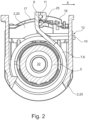
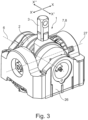
- the present invention relates to an operating unit comprising a housing for at least partially accommodating a control adapter and restoring means, wherein the restoring means are at least two torsion spring.
- Operating levers are widely used in agricultural vehicles. They are commonly controlled by an operating unit. The form of the operating unit amongst others gives rise to an opposing force enabling user feedback in an electric steering system.
- the operating lever In use, the operating lever is pivoted by a user.
- the operating lever is connected to the operating unit via a control adapter, which transfers the motion of the operating lever to the operating unit.
- restoring means are provided, commonly in form of a single torsion spring.
- the mentioned operating levers are commonly moved in at least two opposite directions and have to undergo multiple motion cycles. Therefore, the torsion spring has to be designed to withstand these numerous load-cycles through a long lifetime and maintain a blacklash-free re-positioning. This requirement leads to a rather large torsion spring that disadvantageously requires a large space within a housing of the operating unit.
- the problem to be solved is to provide an operating unit requiring a minimum space as well as providing for an effective and blacklash-free restoring of the operating unit's operating lever.
- the operating unit according to the invention is mounted in a further outer housing, while the operating unit is relatively pivotally mounted in the outer housing along a pivoting axis, wherein the pivoting axis is perpendicularly orientated to the longitudinal axis.
- a user is able to pivot the operating lever, which transfers its motion through the control adapter to the operating unit in any pivoting direction, since the control adapter can be pivoted by itself and/or relatively by the pivoting motion of the housing.
- additional restoring means are accommodated to restore the housing in its initial position, when the operating lever is released by the user.
- additional restoring means correspond to the restoring means partly accommodated in the housing, wherein the additional restoring means are at least two further torsion springs each comprising a first end and a second end, wherein the first ends rest against the housing and the second ends rest against the outer housing.
- the control adapter comprises at least one adapter stop to rest each first end of the restoring means there against and the housing comprises at least one housing stop to rest each second end of the restoring means there against.
- the control adapter and the housing are connected indirectly through the restoring means.
- the adapter stop und the housing stop are designed in such a way, that no further components are needed for resting the first and second end there against.
- the second end is positively connected to the housing stop and/or the first end is positively connected to the adapter stop.
- the housing provides preferably two housing stops, which are positioned opposite to each other and the control adapter and the restoring means in between.
- a preferable development of the invention provides that at least two first ends of the restoring means rest on different adapter surfaces of the adapter stop, wherein the different adapter surfaces oppose each other. Every motion of the control adapter is preferably restored by a different torsion spring. Also more than one torsion spring can restore the control adapter to its initial position, while such a group of torsion springs rest on the identical adapter surface. By opposing the adapter surfaces to each other, the control adapter is reliably restored after a deflection in two opposing pivot directions. Thus, only a few of the restoring means are used while deflecting the control adapter.
- each torsion spring is thus halved, leading to the advantage, that the torsion spring can be designed smaller, thereby reducing the required space for mounting.
- deformations on the adapter surfaces and/or the first ends lead to the adapter surfaces getting a substantially concave shape. Due to resting of the torsion springs on the opposite adapter surfaces, a tolerance of the initial position will be improved since the initial torques of the torsion springs affect against each other additionally to a stop. Thus, a blacklash-free re-positioning / restoring is provided during the whole lifetime of the operating unit.
- the adapter stop has two grooves that are opposed to each other, that the first ends of at least two torsion springs each are insertable in the grooves of the adapter stop to provide a reliable rest of the first ends on the adapter surfaces.
- the adapter surfaces are preferably formed by the bottom surfaces of the grooves.
- an embodiment of the invention provides that the at least two torsion springs have a different spring ratio and/or a rectangular cross section.
- the spring ratio is chosen to provide sufficient resistance to get the user a clear feedback and to reliably restore the control adapter towards a starting position. While different torsion springs interact as restoring means during different motions, the choice of the spring ratio also depends, whether a user needs to push or pull the operating lever and thus the control adapter.
- the at least one torsion spring absorbs a relative motion between the control adapter and the housing, while moving the control adapter in one first pivot direction and the other at least one torsion spring absorbs another relative motion between the control adapter and the housing, while moving the control adapter in one second pivot direction, which opposes the first pivot direction.
- different torsion springs provide different restoring torques regarding to the pivot direction a user moves the control adapter.
- the rectangular cross section provides surfaces by which especially the first and second end of the torsion spring can be rested to other components. Further, the manufacturing of torsion springs with such a shape is easy and cheap. The use of torsion springs with a circular cross section is also possible.
- a spring angle which is defined between the first end and the second end of each torsion spring, is preferably 90° in an initial position of the control adapter and not deflected.
- the spring angle is preferably between 110° and 120°, in particular 115° in a maximum deflected position of the control adapter.
- An initial torque of the torsion spring in the initial position of the control adapter is preferably between 0.5 Nm and 2 Nm, in particular between 0.75 Nm and 1.5 Nm.
- the maximum torque of the torsion spring in the maximum deflected position of the control adapter is preferably between 0.75 Nm and 3 Nm, in particular between 0.9 Nm and 2.5 Nm.
- the cross-sectional shape of the torsion spring can be increased and or the amount of windings of the torsion spring can be increased.
- the restoring means are orientated axisymmetric, perpendicular to the lever adapter.
- Torsion springs are able to receive a generated force during a rotational motion.
- the restoring means of the at least two torsion springs are substantially coaxially mounted to the bearing seat, wherein the at least two torsion springs have a hollow cylindrical shape and the first end and second end extending from the cylindrical shape.
- the lever adapter is perpendicularly orientated to the longitudinal axis of the bearing seat.
- the bearing seat is preferably positioned at a lever end of the lever adapter or in between the lever adapter.
- the axis symmetry of the restoring means to the lever adapter provides for a steady external force to the control adapter and therefore to a bearing, which indirectly connects the control adapter with a control shaft, which is statically mounted in the housing.
- the axes of the lever adapter and the restoring means are orientated perpendicular to each other.
- the operating unit comprises a sliding sleeve, wherein the sliding sleeve is mounted between the bearing seat und the restoring means.
- the sliding sleeve is preferably mounted coaxially to the bearing seat and is statically mounted on the housing.
- the sliding sleeve does not contact the control adapter directly, while it separates the control adapter from the restoring means to reduce friction during a motion of the control adapter in use.
- the sliding sleeve comprises two equal sleeve portions, which are substantially cylindrical. Each sleeve portion has a first axial end a second axial end and an outwardly directed receiving region between the first and the second axial end for receiving at least one torsion spring on each of the sleeve portions.
Landscapes
- Physics & Mathematics (AREA)
- General Physics & Mathematics (AREA)
- Engineering & Computer Science (AREA)
- Automation & Control Theory (AREA)
- Chairs For Special Purposes, Such As Reclining Chairs (AREA)
Priority Applications (5)
| Application Number | Priority Date | Filing Date | Title |
|---|---|---|---|
| EP23220481.8A EP4579376A1 (fr) | 2023-12-28 | 2023-12-28 | Unité de commande |
| PCT/EP2024/083168 WO2025140806A1 (fr) | 2023-12-28 | 2024-11-21 | Unité de commande |
| PCT/EP2024/087526 WO2025140935A1 (fr) | 2023-12-28 | 2024-12-19 | Levier d'actionnement à système de liaison et procédé de fonctionnement |
| PCT/EP2024/087522 WO2025140934A1 (fr) | 2023-12-28 | 2024-12-19 | Système de liaison, levier de commande avec système de liaison et procédé de fonctionnement |
| PCT/EP2024/087527 WO2025140936A2 (fr) | 2023-12-28 | 2024-12-19 | Manchon coulissant, unité d'actionnement et procédé de fabrication d'une unité d'actionnement |
Applications Claiming Priority (1)
| Application Number | Priority Date | Filing Date | Title |
|---|---|---|---|
| EP23220481.8A EP4579376A1 (fr) | 2023-12-28 | 2023-12-28 | Unité de commande |
Publications (1)
| Publication Number | Publication Date |
|---|---|
| EP4579376A1 true EP4579376A1 (fr) | 2025-07-02 |
Family
ID=89474258
Family Applications (1)
| Application Number | Title | Priority Date | Filing Date |
|---|---|---|---|
| EP23220481.8A Pending EP4579376A1 (fr) | 2023-12-28 | 2023-12-28 | Unité de commande |
Country Status (1)
| Country | Link |
|---|---|
| EP (1) | EP4579376A1 (fr) |
Citations (4)
| Publication number | Priority date | Publication date | Assignee | Title |
|---|---|---|---|---|
| JP2007323188A (ja) * | 2006-05-30 | 2007-12-13 | Komatsu Ltd | 操作レバー装置 |
| EP3232295A2 (fr) * | 2016-04-13 | 2017-10-18 | MAKERSAN Makina Otomotiv Sanayi Ticaret Ltd. Sti. | Levier de commande pour un fonctionnement précis |
| EP3508956A1 (fr) * | 2016-08-31 | 2019-07-10 | Autel Robotics Co., Ltd. | Télécommande et son dispositif de manette de jeu |
| US20230318504A1 (en) * | 2022-03-31 | 2023-10-05 | Yamaha Hatsudoki Kabushiki Kaisha | Motor control system, drive unit and electric vehicle |
-
2023
- 2023-12-28 EP EP23220481.8A patent/EP4579376A1/fr active Pending
Patent Citations (4)
| Publication number | Priority date | Publication date | Assignee | Title |
|---|---|---|---|---|
| JP2007323188A (ja) * | 2006-05-30 | 2007-12-13 | Komatsu Ltd | 操作レバー装置 |
| EP3232295A2 (fr) * | 2016-04-13 | 2017-10-18 | MAKERSAN Makina Otomotiv Sanayi Ticaret Ltd. Sti. | Levier de commande pour un fonctionnement précis |
| EP3508956A1 (fr) * | 2016-08-31 | 2019-07-10 | Autel Robotics Co., Ltd. | Télécommande et son dispositif de manette de jeu |
| US20230318504A1 (en) * | 2022-03-31 | 2023-10-05 | Yamaha Hatsudoki Kabushiki Kaisha | Motor control system, drive unit and electric vehicle |
Similar Documents
| Publication | Publication Date | Title |
|---|---|---|
| US9580100B2 (en) | Steering system | |
| US9242722B2 (en) | Joystick for controlling an aircraft | |
| US6299544B1 (en) | Double offset joint with centering means for cage | |
| US10981590B2 (en) | Steering column assembly | |
| EP1892437A2 (fr) | Mécanisme de sélection de retour | |
| KR102003364B1 (ko) | 컬랩서블 스티어링 칼럼 어셈블리 | |
| TWI529043B (zh) | 操縱裝置 | |
| EP3031696B1 (fr) | Système de direction | |
| US5660078A (en) | Yoke apparatus for rack and pinion | |
| EP4328405A1 (fr) | Appareil d'ouverture et de fermeture de boîte à gants et ensemble boîte à gants le comprenant | |
| EP4579376A1 (fr) | Unité de commande | |
| CN108027626A (zh) | 具有致动阻尼的踏板装置 | |
| EP2045826B1 (fr) | Ensemble de commutation électrique | |
| EP4321376A1 (fr) | Dispositif d'inclinaison pour siège de véhicule | |
| EP4306357B1 (fr) | Dispositif d'inclinaison pour siège de véhicule | |
| US7306259B2 (en) | Lock for tilting and telescoping steering column | |
| WO2023038013A1 (fr) | Dispositif de colonne de direction | |
| WO2025140806A1 (fr) | Unité de commande | |
| KR920007862B1 (ko) | 도어미러 미러본체각도조정기구 | |
| US12485802B2 (en) | Recliner for vehicle seat | |
| EP4579375A1 (fr) | Manchon coulissant, unité de commande et procédé de fabrication d'une unité de commande | |
| WO2025140936A2 (fr) | Manchon coulissant, unité d'actionnement et procédé de fabrication d'une unité d'actionnement | |
| CN114132235B (zh) | 弹性元件和具有弹性元件的车辆座椅 | |
| KR102034211B1 (ko) | 스티어링 컬럼 | |
| KR101573996B1 (ko) | 스티어링 칼럼 부품 상의 스티어링 드롭 아암의 베어링 장치, 및 이러한 유형의 베어링 장치를 갖는 자동차 |
Legal Events
| Date | Code | Title | Description |
|---|---|---|---|
| PUAI | Public reference made under article 153(3) epc to a published international application that has entered the european phase |
Free format text: ORIGINAL CODE: 0009012 |
|
| STAA | Information on the status of an ep patent application or granted ep patent |
Free format text: STATUS: THE APPLICATION HAS BEEN PUBLISHED |
|
| AK | Designated contracting states |
Kind code of ref document: A1 Designated state(s): AL AT BE BG CH CY CZ DE DK EE ES FI FR GB GR HR HU IE IS IT LI LT LU LV MC ME MK MT NL NO PL PT RO RS SE SI SK SM TR |
|
| STAA | Information on the status of an ep patent application or granted ep patent |
Free format text: STATUS: REQUEST FOR EXAMINATION WAS MADE |
|
| 17P | Request for examination filed |
Effective date: 20260102 |
|
| STAA | Information on the status of an ep patent application or granted ep patent |
Free format text: STATUS: THE APPLICATION IS DEEMED TO BE WITHDRAWN |