EP4579391A2 - Terminal mobile - Google Patents
Terminal mobile Download PDFInfo
- Publication number
- EP4579391A2 EP4579391A2 EP25173646.8A EP25173646A EP4579391A2 EP 4579391 A2 EP4579391 A2 EP 4579391A2 EP 25173646 A EP25173646 A EP 25173646A EP 4579391 A2 EP4579391 A2 EP 4579391A2
- Authority
- EP
- European Patent Office
- Prior art keywords
- frame
- mobile terminal
- display unit
- region
- flexible display
- Prior art date
- Legal status (The legal status is an assumption and is not a legal conclusion. Google has not performed a legal analysis and makes no representation as to the accuracy of the status listed.)
- Pending
Links
Images


Classifications
-
- G—PHYSICS
- G06—COMPUTING OR CALCULATING; COUNTING
- G06F—ELECTRIC DIGITAL DATA PROCESSING
- G06F1/00—Details not covered by groups G06F3/00 - G06F13/00 and G06F21/00
- G06F1/16—Constructional details or arrangements
- G06F1/1613—Constructional details or arrangements for portable computers
- G06F1/1615—Constructional details or arrangements for portable computers with several enclosures having relative motions, each enclosure supporting at least one I/O or computing function
- G06F1/1624—Constructional details or arrangements for portable computers with several enclosures having relative motions, each enclosure supporting at least one I/O or computing function with sliding enclosures, e.g. sliding keyboard or display
-
- G—PHYSICS
- G06—COMPUTING OR CALCULATING; COUNTING
- G06F—ELECTRIC DIGITAL DATA PROCESSING
- G06F1/00—Details not covered by groups G06F3/00 - G06F13/00 and G06F21/00
- G06F1/16—Constructional details or arrangements
- G06F1/1613—Constructional details or arrangements for portable computers
- G06F1/1633—Constructional details or arrangements of portable computers not specific to the type of enclosures covered by groups G06F1/1615 - G06F1/1626
- G06F1/1637—Details related to the display arrangement, including those related to the mounting of the display in the housing
- G06F1/1652—Details related to the display arrangement, including those related to the mounting of the display in the housing the display being flexible, e.g. mimicking a sheet of paper, or rollable
-
- G—PHYSICS
- G06—COMPUTING OR CALCULATING; COUNTING
- G06F—ELECTRIC DIGITAL DATA PROCESSING
- G06F1/00—Details not covered by groups G06F3/00 - G06F13/00 and G06F21/00
- G06F1/16—Constructional details or arrangements
- G06F1/1613—Constructional details or arrangements for portable computers
- G06F1/1633—Constructional details or arrangements of portable computers not specific to the type of enclosures covered by groups G06F1/1615 - G06F1/1626
- G06F1/1684—Constructional details or arrangements related to integrated I/O peripherals not covered by groups G06F1/1635 - G06F1/1675
- G06F1/1686—Constructional details or arrangements related to integrated I/O peripherals not covered by groups G06F1/1635 - G06F1/1675 the I/O peripheral being an integrated camera
-
- H—ELECTRICITY
- H04—ELECTRIC COMMUNICATION TECHNIQUE
- H04M—TELEPHONIC COMMUNICATION
- H04M1/00—Substation equipment, e.g. for use by subscribers
- H04M1/02—Constructional features of telephone sets
- H04M1/0202—Portable telephone sets, e.g. cordless phones, mobile phones or bar type handsets
- H04M1/0206—Portable telephones comprising a plurality of mechanically joined movable body parts, e.g. hinged housings
- H04M1/0208—Portable telephones comprising a plurality of mechanically joined movable body parts, e.g. hinged housings characterized by the relative motions of the body parts
- H04M1/0235—Slidable or telescopic telephones, i.e. with a relative translation movement of the body parts; Telephones using a combination of translation and other relative motions of the body parts
- H04M1/0237—Sliding mechanism with one degree of freedom
-
- H—ELECTRICITY
- H04—ELECTRIC COMMUNICATION TECHNIQUE
- H04M—TELEPHONIC COMMUNICATION
- H04M1/00—Substation equipment, e.g. for use by subscribers
- H04M1/02—Constructional features of telephone sets
- H04M1/0202—Portable telephone sets, e.g. cordless phones, mobile phones or bar type handsets
- H04M1/0206—Portable telephones comprising a plurality of mechanically joined movable body parts, e.g. hinged housings
- H04M1/0241—Portable telephones comprising a plurality of mechanically joined movable body parts, e.g. hinged housings using relative motion of the body parts to change the operational status of the telephone set, e.g. switching on/off, answering incoming call
-
- H—ELECTRICITY
- H04—ELECTRIC COMMUNICATION TECHNIQUE
- H04M—TELEPHONIC COMMUNICATION
- H04M1/00—Substation equipment, e.g. for use by subscribers
- H04M1/02—Constructional features of telephone sets
- H04M1/0202—Portable telephone sets, e.g. cordless phones, mobile phones or bar type handsets
- H04M1/026—Details of the structure or mounting of specific components
- H04M1/0264—Details of the structure or mounting of specific components for a camera module assembly
-
- H—ELECTRICITY
- H04—ELECTRIC COMMUNICATION TECHNIQUE
- H04M—TELEPHONIC COMMUNICATION
- H04M1/00—Substation equipment, e.g. for use by subscribers
- H04M1/02—Constructional features of telephone sets
- H04M1/0202—Portable telephone sets, e.g. cordless phones, mobile phones or bar type handsets
- H04M1/026—Details of the structure or mounting of specific components
- H04M1/0266—Details of the structure or mounting of specific components for a display module assembly
- H04M1/0268—Details of the structure or mounting of specific components for a display module assembly including a flexible display panel
-
- H—ELECTRICITY
- H04—ELECTRIC COMMUNICATION TECHNIQUE
- H04M—TELEPHONIC COMMUNICATION
- H04M2201/00—Electronic components, circuits, software, systems or apparatus used in telephone systems
- H04M2201/38—Displays
-
- H—ELECTRICITY
- H04—ELECTRIC COMMUNICATION TECHNIQUE
- H04M—TELEPHONIC COMMUNICATION
- H04M2250/00—Details of telephonic subscriber devices
- H04M2250/22—Details of telephonic subscriber devices including a touch pad, a touch sensor or a touch detector
Definitions
- the present disclosure relates to a mobile terminal, and more particularly, to a mobile terminal that has a flexible display and is capable of extending a size of a screen while the display is scrolled and slid at the same time.
- Terminals may be generally classified as mobile/portable terminals or stationary terminals according to their mobility. Mobile terminals may also be classified as handheld terminals or vehicle mounted terminals according to whether or not a user can directly carry the terminal.
- a display device is a device having a function of receiving, processing, and displaying a video that a user may watch. For example, the display device receives a broadcast selected by the user from broadcast signals transmitted from a broadcasting station, separates a video signal from the received signals, and displays the separated video signal on a display.
- the display device has been developed to provide not only broadcast contents but also various other contents to the user.
- the display device may provide game play, music listening, internet shopping, user customized information, and the like using various applications as well as programs received from the broadcasting station.
- the display device may be basically connected to other devices or networks using various communication protocols, and may provide the user with an ubiquitous computing environment.
- the display device has evolved into a smart device that enables connectivity to a network and continuous computing.
- a size of the mobile terminal may be varied using a deforming property of the flexible display.
- a change in the structure of the mobile terminal must be performed stably.
- a support structure and the like of the variable display unit may be a problem.
- One purpose of the present disclosure is to provide a mobile terminal that may improve durability of a flexible display unit by not restricting a point where the flexible display unit is bent to a specific position.
- the mobile terminal of the present disclosure reduces a friction between the first frame and the second frame through a simple slide structure, so that conversion between a first state and a second state is easy.
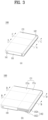
- the mobile terminal 100 of the present disclosure includes frames 101 and 102 in which components are mounted, and the frames 101 and 102 of the present disclosure may vary in size in the first direction as shown in FIG. 2 .
- One or more frames 101 and 102 move relative to each other, and sizes thereof may vary in the first direction.
- Electronic components are mounted in the frames 101 and 102, and the flexible display unit 151 is located out of the frames 101 and 102.
- the physical input unit 120 for the manipulation of the mobile terminal 100 such as various buttons, switches, the camera 121, and a flash, and the sensing unit 140 such as the proximity sensor 141 or a fingerprint sensor may be arranged on the exposed rear portion 1013.
- the first rear portion 1012 except for the exposed rear portion 1013 may be covered by the display unit 151 in the first state as shown in FIG. 4A , and may be exposed rearwardly in the second state as shown in FIG. 4B .
- the display unit 151 is positioned both the front face and the rear face of the mobile terminal 100 of the present disclosure. Therefore, when the user captures himself or herself, a display unit on the same face as the camera 121, that is, the portion of the display 151 on the rear face of the mobile terminal 100 in the drawing may be used. Further, when the user captures the object on the opposite side of the user, a display unit on the opposite face of the camera 121, that is, the portion of the display unit 151 on the front face of the mobile terminal 100 in the drawing may be used. For this reason, the mobile terminal 100 may capture the object on the opposite side of the user and capture the user using the single camera 121.
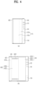
- the side portion 1014 may extend along edges of the first front portion 1011 and the first rear portion 1012 to surround the first frame 101, and may form the outer shape of the mobile terminal 100.
- the second frame 102 since the second frame 102 is accommodated in the first frame 101 and is movably coupled thereto, in order to allow the movement of the second frame 102 relative to the first frame 101, a portion of the first frame 101 needs to be opened.
- the second frame 102 is movably coupled to one of both side portions of the first frame 101, so that the side portion 1014 may not be formed on the side portion in the first direction, and thus, the portion of the first frame 101 may be opened.
- the first frame 101 may include a substantially closed first side portion 101a and a second side portion 101b, which is disposed to be opposite to the first side portion 101a and is opened.
- the side portion 1014 is exposed to the outside of the mobile terminal 100, so that an interface unit 160 for connecting a supply port or an ear jack, the user input unit 120 such as a volume button, or the like may be disposed on the side portion 1014.
- the side portion 1014 may serve as an antenna.
- the second frame 102 may include a second front portion 1021 disposed at the front portion of the mobile terminal 100 and a second rear portion 1022 disposed at the rear portion of the mobile terminal 100.
- the second front portion 1021 and the second rear portion 1022 may be formed of plate-shaped members that are generally flat.
- the second frame 102 also accommodates various components, and must not interfere with the components accommodated in the first frame 101 during the movement. Accordingly, the second front portion 1021 and the second rear portion 1022 may be coupled to each other in a state of being spaced apart from each other to define a predetermined space therebetween, and may have shapes that do not interfere with the components in the first frame 101.
- the display unit 151 may be bent 180 degrees while being rolled in the second frame 102 to be disposed on both the front face and the rear face of the mobile terminal 100.
- the second frame 102 may include a roller 1028 rotatably disposed therein.
- the roller 1028 may be disposed at any position inside the second frame 102.
- the display unit 151 should be spread flat on the front face and the rear face of the mobile terminal 100 to provide a good quality screen to the user. Further, for such spread, a proper tension must be provided on the display unit 151.
- the roller 1028 may be disposed at a first directional end of the second frame 102.
- the roller 1028 may extend in the third direction, and may be rotatably coupled to the second frame 102.
- the display unit 151 may be rolled around the roller 1028 while being gently bent with a predetermined curvature.
- the flexible display unit 151 may include a first face on which a video is output and exposed to the outside and an inner face facing the frame at the opposite side.
- the roller 1028 may be installed to rotate freely in the second frame 102 while being in contact with the inner face of the display unit 151. Accordingly, the roller 1028 may actually move the display unit 151 in a lateral direction of the mobile terminal 100, that is, in a direction perpendicular to a longitudinal direction.
- the display unit 151 moves to the front face or the rear face of the mobile terminal 100 in different directions (i.e., the first direction D1 or the second direction D2) relative to the second frame 102.
- the roller 1028 may guide such movement while rotating.
- the roller 1028 is disposed on a first side portion 102a of the second frame 102, and the first side portion 102a actually corresponds to an outermost side portion of the mobile terminal 100.
- the display unit 151 rolled on the roller 1028 may be damaged.
- the second frame 102 may include a side frame 1024 disposed on the first side portion 102a.
- the side frame 1024 extends in the longitudinal direction of the second frame 102 to cover the first side portion 102a, thereby protecting the roller 1028 and the display unit 151 rolled thereon.
- an inner face of the side frame may include a curved face corresponding to the curvature of the side face.
- the second frame 102 may have the substantially closed first side portion 102a, and the side frame 1024 may substantially form the outer shape of the mobile terminal 100 together with the side portion 1014 of the first frame 101.
- the second frame 102 may include a second side portion 102b that is disposed opposite the first side portion 102a to minimize interference with the components within the first frame 101 during the movement, and is opened.
- Such a second frame 102 is movably coupled to the first frame 101, and thus may slide in the predetermined first or second direction D1 or D2 relative to the first frame 101. More specifically, the second frame 102 may be movably coupled to the first frame 101 through the side portion of the first frame 101, more precisely, through the opened second side portion 101b, as shown. More specifically, the second side portion 102b of the second frame is disposed relatively adjacent to the first side portion 101a of the first frame 101 which is closed. Accordingly, the first side portion 102a of the second frame may be disposed to be opposite to the first side portion 101a. Accordingly, the second side portion 102b is inserted into the first frame 101 through the side portion of the first frame, that is, the second side portion 101b thereof.
- the first side portion 102b is not inserted into the first frame 101 but is always located outside the first frame 101, thereby forming the outer shape of the mobile terminal 100 as described above. However, when necessary, such first side portion 102b of the second frame 102 may also be inserted into the first frame 101.
- the second frame 102 contracts to the first frame 101.
- the second direction D1 is a direction opposite to the first direction D1, so that the second direction D2 may be a direction in which the second frame 102 moves to become closer to the first frame 101, that is, moves inwardly of the mobile terminal 100 or the first frame 101.
- such second frame 102 extends and applies a force to the portion of the display unit 151 disposed on the rear face of the mobile terminal 100, so that the portion of the display unit 151 may be disposed on the front face of the mobile terminal 100, and a region for such additional arrangement may be defined.
- the state conversion may be performed manually by the user, and an operation of the mobile terminal 100 during such manual state conversion will be described.
- operations of the first to third frames 101 to 103 and the display unit 151 which will be described below, may be performed in the same manner when a power source other than a user's force is used, for example, when the driving unit 200 to be described below is applied.
- the exposed decor 1013 may be further attached to the exposed rear portion of the first rear portion 1011 to protect the camera 121, the sensor 140, and the like.
- the exposed decor 1013 may be partially coated on a plate-shaped member made of a transparent glass material to cover the internal components, and may be not coated only on a required portion to allow light to reach the camera 121, the flash or the sensing unit 140, and the like.
- a side case may contain a conductive material for the touch input.
- a protrusion may be formed on a portion containing the conductive material, so that the user may touch the protrusion to input a user command.
- An inner face of the side frame 1024 corresponding to a curvature of the flexible display unit 151 rolled on the roller 1028 may have a middle portion that is formed more thicker as shown in FIG. 6 , so that the side frame 1024 may secure rigidity while having a natural curved face.
- the transparent portion 1024b of a predetermined pattern may be formed to drive the flexible display unit 151, thereby providing a notification to the user.
- the flexible display unit 151 may be driven to sequentially emit light.
- the flexible display unit 151 rolled on the roller 1028 may provide the notification by emitting light of a specific color. Therefore, the user may receive the notification using the flexible display unit 151 without the separate optical output module 154. In this connection, light may spread softly on the transparent portion 1024b using a translucent material rather than the transparent material.
- a width of an area of the side frame 1024 in a thickness direction may be reduced to implement a terminal having an edge region extending from an end of the display unit to a portion in a side direction.
- the side frame 1024 may prevent a breakage that occurs when the bent face of the flexible display unit 151 is exposed to the outside using an out-folding scheme, so that a durability of the roll-slide mobile terminal 100 may be improved.
- FIG. 7 illustrates a configuration of the roller 1028 and the flexible display unit 151 as well as the side frame 1024.
- the flexible display unit 151 of the present disclosure may include a display panel 151b for outputting the video and a back plate 151c for supporting a rear face of the display panel 151b.
- the display panel 151b which is a flexible video display device, may be, for example, an organic light emitting diode (OLED).
- the back plate 151c may be formed on the rear face of the display panel 151b, and may use a metal plate that has a rigidity to support the display panel 151b and is able to be bent when the display panel 151b is bent.
- a region of the back plate 151c corresponding to the third region may have a groove defined in a surface thereof extending in the third direction such that the bending occurs naturally during the bending deflection of the third region.
- the support frame 1515 may include a plurality of rigid bars 1515a in a form of a bar extending in the third direction, which are consecutively arranged in the first direction. Since a width thereof in the first direction is not large, the rigid bar 1515a may be formed in a thickness to have a predetermined rigidity while minimizing an affect on the bending deflection of the flexible display unit 151 to support the rear face of the flexible display unit 151.
- the rigid bar 1515a may have a trapezoidal or triangular cross section such that an area of a portion adhere to the back plate 151c is larger than an area of an opposite face in order to avoid interference between the rigid bars 1515a especially when the back plate 151c is bent.
- the rigid bar 1515a may be formed using a plastic injection-molding scheme, and when necessary, as shown in Figure 6B , a metal member 1515b may be inserted inside the rigid bar 1515a to reinforce the rigidity of the support frame 1515.
- the support frame 1515 may have a thickness corresponding to a thickness of the first front portion 1011 of the first frame 101.
- the second front portion 1021 positioned inside the first front portion 1011 is positioned on the rear face of the second region 151b of the flexible display unit 151.
- a space having a size corresponding to a thickness of the first front portion 1011 is defined between the second front portion 1021 and the back plate 151c, so that the third region 1513 of the flexible display unit 151 sags.
- the support frame 1515 supports the third region 151c of the flexible display unit 151 while filling the space between the second front portion 1021 and the back plate 151c.
- the support frame 1515 may have a thickness corresponding to the space between the second front portion 1021 and the back plate 151c, that is, the thickness of the first front portion 1011.
- the second front portion 1021 of the second frame 102 may be omitted.
- the thickness of the support frame 1515 may be defined regardless of the first front portion 1011 of the first frame.
- the roller 1028 is in contact with a rear face of the support frame 1515. Further, in order for the flexible display unit 151 to be rolled on the roller 1028 without being pushed, a first tooth 1028a may be formed on a surface of the roller 1028 as shown in FIG. 6C , and a second tooth 1515c to be engaged with the first tooth 1028a may be formed on a surface of the support frame 1515. Alternatively, as shown in FIG. 6B , the first tooth 1028a may have a width corresponding to a spacing between two adjacent rigid bars 1515a. The roller 1028 may rotate in a state in which each protrusion 1028a is inserted between the two adjacent rigid bars 1515a.
- a rear face cover 104 for covering the rear face of the roll-slide mobile terminal 100 may be further included. At least a portion of the rear face cover 104 is transparent, so that video output from the flexible display unit 151 positioned at the rear face may be identified. At least a portion for covering the first rear portion 1012 corresponding to the camera 121, the flash, or the like may be formed to be transparent.
- the rear face cover 104 may be coupled to the first frame 101 to cover the first rear portion 1012, and may be spaced apart from the first rear portion 1012 by a spacing corresponding to thicknesses of the second rear portion 1022 of the second frame 102, the slide frame 103, and the flexible display unit 151.
- the rear face cover 104 may cover the flexible display unit 151 when the roll-slide mobile terminal 100 is in the first state, and may cover the first rear portion 1012 exposed after the flexible display unit 151 is moved forwardly in the second state.
- the slide frame 103 is coupled to the rear face of the second rear portion 1022 positioned at the rear face, and the slide frame 103 moves along the rear face of the second rear portion 1022.
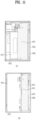
- FIG. 8A illustrates the rear face of the second rear portion 1022 and the rear face of the display unit 151.
- the screen When the curved face is located at the end of the display unit 151, the screen may look wide, but the display unit 151 receives a force as the second frame 102 moves, and the region of the front face of the display unit 151 varies. Since the force is applied to the first region of the display unit 151 when the second frame 102 and the slide frame 103 are moved, a structure that strongly supports the first region is required. As shown in FIG. 5 , a curved face bracket 1016 may be coupled to the first side edge 151d of the display unit 151 to be against the force applied to the display unit 151 when converting from the first state to the second state.
- a portion of the display unit 151 near the second side edge 151e may be rolled on the roller 1028 and positioned on the rear face of the second rear portion 1022, and the other portion thereof may be disposed forwardly of the second rear portion 1022 as shown in FIG. 8B such that the slide frame 103 is positioned on the rear face of the second rear portion 1022.
- the portion rolled on the roller 1028 and bent is not simply bent, but moves sequentially.
- a force may be applied to the display unit 151. Since a force pulled by the driving unit 200 is greatly applied to the bent portion, the portion rolled on the roller 1028 or the curved portion of the first end of the display unit 151 is fragile.
- the curved portion of the first end may be reinforced by a structure fixed at the rear face and the front face such that the force by the driving unit 200 may be dispersed without being concentrated in one place.
- the third region rolled on the roller 1028 bends, and when it is converted into the second state, moves from the rear face to the front face. Since the second front portion 1021 of the second frame 102 is positioned on the extended front face and the second front portion 1021 is spaced apart from the display unit 151 farther than the first front portion 1011. the third region may add the support frame 1515 having a thickness corresponding to a thickness of the first front portion 1011 to the rear face. As shown in FIG. 12C , a groove 1515' extending in the third direction may be formed in the rear face of the support frame 1515 such that the support frame 1515 bends corresponding to the deformation of the display unit 151.
- FIG. 13 is a diagram for describing an operation of a driving unit according to one embodiment of the roll-slide mobile terminal 100 associated with the present disclosure.
- the flexible display unit 151 moves by a second distance 2d corresponding to twice the first distance.
- the slide frame 103 In order for the end of the flexible display unit 151 to move by the second distance, the slide frame 103 must also move the same distance as the second frame 102 from the second frame 102.
- the driving unit 210 mounted inside the first frame 101 should be fastened with the slide frame 103 positioned on the rear face of the second rear portion 1022 of the second frame 102. Therefore, a fastener for fastening the third bracket 213 with the slide frame 103 is disposed by passing through the slide slot 1025 defined in the second frame 102. The fastener moves the slide frame 103 while moving along the slide slot 1025 in the first direction, and the third region 151c of the flexible display unit 151 sequentially moves forwardly.
- FIG. 14 is a diagram illustrating an embodiment of the driving unit 200 of a mobile terminal.
- the driving unit 200 may be disposed at an upper portion without being positioned at a central portion. A space having a large area is required to arrange the components such as the battery. When the driving unit 200 is placed in the central portion, it is difficult to mount the battery.
- the driving unit 200 may be disposed to be positionally biased in the third direction, and instead, a pair of linear guides 230 for guiding the movement of the second frame 102 in the first direction or the second direction may be further arranged at both ends of the mobile terminal in the third direction, respectively.
- a plurality of motors 201 may be arranged to apply sufficient driving force to move the second frame 102. As a size thereof is large, the motor 201 may provide a larger force, but a thickness of the mobile terminal may also become large. Therefore, as shown in FIG. 14B , both ends in a thickness direction of the motor are formed in a cut shape to reduce the thickness while ensuring performance.
- a rotational force of the motor 201 may be directly transmitted to the pinion gear 203 of the rack-pinion gears 203 and 204 for moving the second frame 102 in the first direction, but as shown in FIG. 13A , a planetary gear 202 may be further disposed between the pinion gear 203 and the motor 201.
- a plurality of disc gears are engaged with each other.
- the number of revolutions of the pinion gear 203 relative to the number of revolutions of the motor 201 may be adjusted by adjusting a size of the planetary gear 202 and the number of teeth.
- the planetary gear 202 may be used to effectively transmit the rotational force of the motor 201 to the pinion gear 203.
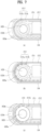
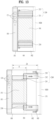
- FIG. 15 shows cross-sectional views respectively taken along a line C-C and a line D-D of FIG. 3 , which are cross-sectional views of the rack-pinion gear portion.
- FIG. 15A shows the first state
- FIG. 15B shows the second state.
- the rack gear 204 moves in a rightward direction as shown in FIG. 15B .
- the pinion gear 203 is fixed to first frame 101
- the rack gear 204 is fixed to the second frame 102.
- the rack gear 204 may be coupled to the second front portion 1021.
- the third region of the display unit 151 moves in a forward direction
- the slide frame 103 moves in the first direction from the rear face of the second rear portion 1022 of the second frame 102, and the area of the portion of the display unit 151 located at the rear face of the mobile terminal is reduced.
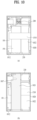
- FIGS. 16 to 18 illustrate various embodiments of the linear guide 230 of the mobile terminal.
- the pair of linear guides 230 of the present disclosure may be disposed at the both ends of the mobile terminal in the third direction, that is, an upper end and a lower end thereof, to complement the function of the single driving unit 200 positionally biased to one side.
- the linear guide 230 may include the guide rail 231 extending in the first direction and the guide block 232 moving along the guide rail 231.
- the guide rail 231 may be disposed in the first frame 101 and the guide block 232 may be disposed in the second frame 102 and vice versa.
- the guide rail 231 may be disposed in the second frame 102 to cover upper and lower portions of the extended portion of the second frame 102 in the second state.
- the fastening of the second front portion 1021 of the second frame 102 with the guide rail 231 may be performed after mounting the second front portion 1021 on the front face of the first rear portion 1012 as shown in FIG. 10B .
- the guide block 232 and the guide rail 231 may be arranged in the third direction in the embodiment of FIG. 16 , and may be arranged in the thickness direction of the mobile terminal 100 in the embodiment of FIG. 17 .
- FIG. 18 illustrates an embodiment in which the insertion portion 2311 of the guide rail 231 has a T-shape and the guide block 232 includes the guide groove 2321 in a shape surrounding the insertion portion 2311.
- the guide rail 231 and the guide block 232 of such shapes have a larger contact area between the guide rail 231 and the guide block 232 than in the above-described embodiment, so that the guide rail 231 and the guide block 232 may be more stably supported, but a frictional force may occur.
- the polyoxymethylene material may be formed on a portion of the guide block 232 in contact with the guide rail 231 in a double injection-molding scheme to reduce the frictional force.
- a groove may be defined in a top face of the guide block 232 such that the polyoxymethylene adheres well to the guide block 232, and the polyoxymethylene may be also injected into the groove in the top face of the block to form a POM rail as shown in FIG. 18B .
- the guide rail 231 may be extrusion-molded by drawing a metallic material, or a plate-shaped member may be press-bent to implement the T-shape. It is possible to implement a beam-shaped member having a T-shaped cross section by folding the plate-like member in half and extending the end outward. The plate-shaped member may be folded in half and an end thereof may be extended outward to implement a beam-shaped member.
- the display unit 151 may be stably fixed through the fixing structure such that the display unit 151 may be prevented from damaging by the force applied to the bent curved face of the display unit 151.
Landscapes
- Engineering & Computer Science (AREA)
- Theoretical Computer Science (AREA)
- Computer Hardware Design (AREA)
- Signal Processing (AREA)
- Physics & Mathematics (AREA)
- Human Computer Interaction (AREA)
- General Engineering & Computer Science (AREA)
- General Physics & Mathematics (AREA)
- Mathematical Physics (AREA)
- Telephone Set Structure (AREA)
- Devices For Indicating Variable Information By Combining Individual Elements (AREA)
Applications Claiming Priority (3)
| Application Number | Priority Date | Filing Date | Title |
|---|---|---|---|
| US201962805920P | 2019-02-14 | 2019-02-14 | |
| PCT/KR2019/016907 WO2020166798A1 (fr) | 2019-02-14 | 2019-12-03 | Terminal mobile |
| EP19915121.8A EP3926933B1 (fr) | 2019-02-14 | 2019-12-03 | Terminal mobile |
Related Parent Applications (1)
| Application Number | Title | Priority Date | Filing Date |
|---|---|---|---|
| EP19915121.8A Division EP3926933B1 (fr) | 2019-02-14 | 2019-12-03 | Terminal mobile |
Publications (2)
| Publication Number | Publication Date |
|---|---|
| EP4579391A2 true EP4579391A2 (fr) | 2025-07-02 |
| EP4579391A3 EP4579391A3 (fr) | 2025-09-10 |
Family
ID=72043652
Family Applications (3)
| Application Number | Title | Priority Date | Filing Date |
|---|---|---|---|
| EP25173646.8A Pending EP4579391A3 (fr) | 2019-02-14 | 2019-12-03 | Terminal mobile |
| EP19915121.8A Active EP3926933B1 (fr) | 2019-02-14 | 2019-12-03 | Terminal mobile |
| EP20756529.2A Active EP3925200B1 (fr) | 2019-02-14 | 2020-01-30 | Terminal mobile |
Family Applications After (2)
| Application Number | Title | Priority Date | Filing Date |
|---|---|---|---|
| EP19915121.8A Active EP3926933B1 (fr) | 2019-02-14 | 2019-12-03 | Terminal mobile |
| EP20756529.2A Active EP3925200B1 (fr) | 2019-02-14 | 2020-01-30 | Terminal mobile |
Country Status (4)
| Country | Link |
|---|---|
| US (2) | US12019474B2 (fr) |
| EP (3) | EP4579391A3 (fr) |
| KR (3) | KR102845067B1 (fr) |
| WO (4) | WO2020166761A1 (fr) |
Families Citing this family (139)
| Publication number | Priority date | Publication date | Assignee | Title |
|---|---|---|---|---|
| KR102845067B1 (ko) * | 2019-02-14 | 2025-08-13 | 엘지전자 주식회사 | 이동 단말기 |
| JP1654801S (ja) * | 2019-04-10 | 2020-03-09 | 携帯電話機 | |
| JP1654799S (ja) * | 2019-04-10 | 2020-03-09 | 携帯電話機 | |
| JP1654802S (ja) * | 2019-04-10 | 2020-03-09 | 携帯電話機 | |
| JP1654795S (ja) * | 2019-04-10 | 2020-03-09 | 携帯電話機 | |
| JP1646030S (fr) * | 2019-04-10 | 2021-11-08 | ||
| JP1646027S (fr) * | 2019-04-10 | 2021-11-08 | ||
| JP7227402B2 (ja) * | 2019-04-18 | 2023-02-21 | 華為技術有限公司 | 電子デバイスの回転表示装置 |
| CN111866225A (zh) * | 2019-04-26 | 2020-10-30 | 北京小米移动软件有限公司 | 电子设备 |
| KR102803889B1 (ko) * | 2019-05-03 | 2025-05-08 | 삼성디스플레이 주식회사 | 표시장치 |
| USD933625S1 (en) * | 2019-06-05 | 2021-10-19 | Huizhou Tcl Mobile Communication Co., Ltd. | Mobile phone |
| JP1653374S (ja) * | 2019-07-11 | 2020-02-25 | 携帯電話機 | |
| JP1653371S (ja) * | 2019-07-11 | 2020-02-25 | 携帯電話機 | |
| JP1653370S (ja) * | 2019-07-11 | 2020-02-25 | 携帯電話機 | |
| US11775016B2 (en) * | 2019-07-19 | 2023-10-03 | Lg Electronics Inc. | Display device |
| CN110491289B (zh) * | 2019-07-29 | 2024-03-15 | 武汉华星光电半导体显示技术有限公司 | 显示装置 |
| JP1663173S (ja) * | 2019-08-08 | 2020-07-06 | 携帯電話機 | |
| JP1663175S (ja) * | 2019-08-27 | 2020-07-06 | 携帯電話機 | |
| KR102832321B1 (ko) * | 2019-10-02 | 2025-07-10 | 삼성디스플레이 주식회사 | 표시 장치 |
| EP4047912B1 (fr) * | 2019-10-18 | 2025-06-18 | LG Electronics, Inc. | Terminal mobile |
| EP4050908B1 (fr) * | 2019-10-24 | 2026-03-04 | Lg Electronics Inc. | Dispositif électronique comprenant un module de haut-parleur |
| EP4080855B1 (fr) * | 2019-12-19 | 2026-02-11 | LG Electronics, Inc. | Terminal mobile déroulant par coulissement |
| CN113010027A (zh) * | 2019-12-19 | 2021-06-22 | Oppo广东移动通信有限公司 | 柔性显示屏组件和电子装置 |
| CN111010829B (zh) * | 2019-12-26 | 2021-03-16 | 维沃移动通信有限公司 | 电子设备 |
| US11755074B2 (en) * | 2019-12-26 | 2023-09-12 | Samsung Display Co., Ltd. | Display device and method of manufacturing supporting part |
| CN113132512B (zh) * | 2019-12-31 | 2022-09-23 | 华为技术有限公司 | 具有卷曲屏的电子设备 |
| CN114982211B (zh) * | 2020-01-24 | 2023-07-18 | 华为技术有限公司 | 用于可滑动显示屏的支撑结构 |
| WO2021193993A1 (fr) | 2020-03-26 | 2021-09-30 | 엘지전자 주식회사 | Terminal mobile |
| KR102713782B1 (ko) * | 2020-04-09 | 2024-10-07 | 엘지전자 주식회사 | 이동 단말기 |
| KR20210130299A (ko) * | 2020-04-21 | 2021-11-01 | 삼성디스플레이 주식회사 | 표시 장치 |
| US11116091B1 (en) * | 2020-04-27 | 2021-09-07 | Wuhan China Star Optoelectronics Semiconductor Display Technology Co., Ltd. | Flexible display screen and display device |
| KR102324562B1 (ko) * | 2020-05-07 | 2021-11-11 | 삼성전자주식회사 | 플렉서블 디스플레이를 포함하는 전자 장치 |
| CN113726947B (zh) * | 2020-05-26 | 2022-09-09 | Oppo广东移动通信有限公司 | 语音通话方法、装置、终端及存储介质 |
| US11315447B2 (en) * | 2020-05-26 | 2022-04-26 | Wuhan China Star Optoelectronics Semiconductor Display Technology Co., Ltd. | Display device |
| CN111510536B (zh) * | 2020-05-26 | 2025-04-25 | 武汉华星光电半导体显示技术有限公司 | 显示装置 |
| CN113851042B (zh) * | 2020-06-28 | 2023-06-02 | Oppo广东移动通信有限公司 | 电子设备 |
| WO2022004908A1 (fr) * | 2020-06-30 | 2022-01-06 | 엘지전자 주식회사 | Dispositif d'affichage flexible |
| CN111833743B (zh) * | 2020-07-02 | 2021-12-28 | 武汉华星光电半导体显示技术有限公司 | 柔性显示装置 |
| WO2022014905A1 (fr) * | 2020-07-14 | 2022-01-20 | 삼성전자 주식회사 | Dispositif électronique comprenant une structure d'agencement de composants électroniques |
| CN116171310A (zh) | 2020-07-14 | 2023-05-26 | 三星电子株式会社 | 包括电子部件布置结构的电子装置 |
| WO2022014908A1 (fr) * | 2020-07-14 | 2022-01-20 | 삼성전자 주식회사 | Dispositif électronique comprenant une structure de support d'écran |
| EP4163759A4 (fr) | 2020-07-14 | 2023-11-29 | Samsung Electronics Co., Ltd. | Dispositif électronique comprenant une structure d'agencement de composants électroniques |
| WO2022015048A1 (fr) | 2020-07-14 | 2022-01-20 | 삼성전자 주식회사 | Dispositif électronique comprenant un écran enroulable |
| EP4167046B1 (fr) | 2020-07-14 | 2024-10-09 | Samsung Electronics Co., Ltd. | Dispositif électronique comprenant une structure de détection |
| KR102863848B1 (ko) * | 2020-07-22 | 2025-09-25 | 삼성전자 주식회사 | 플렉서블 디스플레이 및 안테나를 포함하는 전자 장치 |
| US10893130B1 (en) * | 2020-07-25 | 2021-01-12 | Lg Electronics Inc. | Mobile terminal |
| CN212873896U (zh) * | 2020-08-12 | 2021-04-02 | 京东方科技集团股份有限公司 | 显示装置 |
| KR102845424B1 (ko) * | 2020-08-27 | 2025-08-11 | 엘지전자 주식회사 | 플렉서블 디스플레이 장치 |
| KR102875433B1 (ko) | 2020-09-01 | 2025-10-24 | 삼성전자주식회사 | 플렉서블 디스플레이를 가지는 전자 장치 |
| CN115943451B (zh) * | 2020-09-08 | 2025-03-07 | Lg电子株式会社 | 移动终端 |
| WO2022054997A1 (fr) * | 2020-09-14 | 2022-03-17 | 엘지전자 주식회사 | Terminal mobile |
| KR102846589B1 (ko) * | 2020-09-18 | 2025-08-14 | 삼성전자 주식회사 | 플렉서블 디스플레이 및 디스플레이 지지 구조를 포함하는 전자 장치, 및 디스플레이 지지 구조의 제조 방법 |
| US11989061B2 (en) | 2020-09-23 | 2024-05-21 | Samsung Electronics Co., Ltd. | Electronic device including flexible display |
| KR102290231B1 (ko) * | 2020-09-28 | 2021-08-20 | 삼성전자주식회사 | 플렉서블 디스플레이를 포함하는 전자 장치 |
| KR102274481B1 (ko) * | 2020-10-12 | 2021-07-08 | 삼성전자 주식회사 | 플렉서블 디스플레이를 포함하는 전자 장치 |
| CN116348942A (zh) | 2020-10-12 | 2023-06-27 | 三星电子株式会社 | 包括柔性显示器的电子装置 |
| WO2022080785A1 (fr) * | 2020-10-12 | 2022-04-21 | 삼성전자 주식회사 | Appareil électronique comprenant un écran souple |
| WO2022080694A1 (fr) * | 2020-10-12 | 2022-04-21 | 삼성전자 주식회사 | Dispositif électronique comprenant un écran souple |
| EP4187351A4 (fr) | 2020-10-12 | 2024-01-24 | Samsung Electronics Co., Ltd. | Dispositif électronique comprenant un écran souple |
| KR102256042B1 (ko) * | 2020-10-13 | 2021-05-25 | 삼성전자 주식회사 | 입력을 유도하는 전자 장치 및 방법. |
| KR102892379B1 (ko) * | 2020-10-22 | 2025-12-01 | 엘지전자 주식회사 | 커버 글래스, 커버 글래스 제조방법 및 이동 단말기 |
| CN114495703B (zh) * | 2020-10-27 | 2024-07-02 | 北京小米移动软件有限公司 | 电子设备 |
| KR102848751B1 (ko) * | 2020-10-30 | 2025-08-22 | 삼성전자 주식회사 | 플렉서블 디스플레이의 촬영 안내 방법 및 장치 |
| CN112309258B (zh) * | 2020-11-02 | 2022-08-02 | 昆山国显光电有限公司 | 支撑结构件以及显示设备 |
| KR102784343B1 (ko) * | 2020-11-05 | 2025-03-21 | 삼성전자 주식회사 | 디스플레이 롤링 가이드 구조를 포함하는 전자 장치 |
| KR102289369B1 (ko) * | 2020-11-05 | 2021-08-12 | 삼성전자 주식회사 | 플렉서블 디스플레이에 이미지를 표시하는 전자 장치 및 방법 |
| KR102890042B1 (ko) * | 2020-11-05 | 2025-11-25 | 삼성전자주식회사 | 플렉서블 디스플레이를 포함하는 전자 장치 |
| CN116235235A (zh) * | 2020-11-06 | 2023-06-06 | 三星电子株式会社 | 包括散热构件的电子设备 |
| EP4180905B1 (fr) * | 2020-11-06 | 2026-03-18 | Samsung Electronics Co., Ltd. | Dispositif électronique comprenant un écran souple et son procédé de fonctionnement |
| US11968630B2 (en) | 2020-11-06 | 2024-04-23 | Samsung Electronics Co., Ltd. | Electronic device having slidable structure |
| KR102856524B1 (ko) * | 2020-11-06 | 2025-09-09 | 삼성전자주식회사 | 방열 부재를 포함하는 전자 장치 |
| KR102811198B1 (ko) * | 2020-11-17 | 2025-05-26 | 삼성전자주식회사 | 스피커를 포함하는 전자 장치 및 그 전자 장치의 동작 방법 |
| WO2022108213A1 (fr) * | 2020-11-17 | 2022-05-27 | 삼성전자 주식회사 | Dispositif électronique comprenant un haut-parleur et procédé de fonctionnement dudit dispositif |
| TWI798923B (zh) * | 2020-11-18 | 2023-04-11 | 仁寶電腦工業股份有限公司 | 電子裝置 |
| KR102902110B1 (ko) * | 2020-11-26 | 2025-12-19 | 엘지전자 주식회사 | 이동 단말기 |
| US12613554B2 (en) | 2020-11-26 | 2026-04-28 | Lg Electronics Inc. | Extendable mobile terminal having flexible display unit |
| US11720147B2 (en) * | 2020-12-01 | 2023-08-08 | Samsung Electronics Co., Ltd. | Electronic device including flexible display |
| KR20220077429A (ko) * | 2020-12-02 | 2022-06-09 | 엘지디스플레이 주식회사 | 표시 장치 |
| EP4239444B1 (fr) * | 2020-12-04 | 2025-02-26 | Samsung Electronics Co., Ltd. | Dispositif électronique coulissant |
| EP4224280A4 (fr) * | 2020-12-04 | 2024-04-10 | Samsung Electronics Co., Ltd. | Dispositif électronique comprenant un écran souple |
| CN116583815A (zh) * | 2020-12-04 | 2023-08-11 | 三星电子株式会社 | 包括柔性显示器的电子装置及其操作方法 |
| WO2022119172A1 (fr) * | 2020-12-04 | 2022-06-09 | 삼성전자 주식회사 | Dispositif électronique comprenant un écran souple et procédé de fonctionnement associé |
| CN114596772B (zh) * | 2020-12-07 | 2024-05-24 | 北京小米移动软件有限公司 | 显示屏伸缩驱动机构和电子设备 |
| CN114598759B (zh) * | 2020-12-07 | 2026-03-27 | 北京小米移动软件有限公司 | 电子设备 |
| EP4227761A4 (fr) * | 2020-12-23 | 2024-04-17 | Samsung Electronics Co., Ltd. | Dispositif électronique pouvant être roulé |
| US12581001B2 (en) | 2021-01-25 | 2026-03-17 | Lg Electronics Inc. | Mobile terminal |
| CN116868560A (zh) * | 2021-02-26 | 2023-10-10 | Lg电子株式会社 | 移动终端 |
| EP4246714A4 (fr) | 2021-04-05 | 2024-07-03 | Samsung Electronics Co., Ltd. | Antenne et dispositif électronique la comprenant |
| CN113099008B (zh) * | 2021-04-15 | 2023-11-10 | 维沃移动通信有限公司 | 电子设备 |
| KR102947551B1 (ko) * | 2021-04-21 | 2026-04-02 | 삼성전자주식회사 | 플렉서블 디스플레이 제어 방법 및 이를 지원하는 전자 장치 |
| CN113114821B (zh) * | 2021-04-29 | 2023-03-10 | 维沃移动通信有限公司 | 电子设备 |
| EP4246501B1 (fr) | 2021-05-17 | 2026-03-25 | Samsung Electronics Co., Ltd. | Dispositif électronique comprenant un dispositif d'affichage flexible |
| CN113329109B (zh) * | 2021-05-20 | 2022-12-27 | 维沃移动通信有限公司 | 电子设备 |
| CN115529776A (zh) * | 2021-06-25 | 2022-12-27 | 北京小米移动软件有限公司 | 一种滑轨机构、伸缩屏结构及电子设备 |
| CN115529366A (zh) * | 2021-06-25 | 2022-12-27 | 北京小米移动软件有限公司 | 一种滑轨机构、伸缩屏结构及电子设备 |
| CN115529367B (zh) * | 2021-06-25 | 2025-08-26 | 北京小米移动软件有限公司 | 一种电子设备 |
| CN115529365A (zh) * | 2021-06-25 | 2022-12-27 | 北京小米移动软件有限公司 | 一种驱动机构及电子设备 |
| KR20230003824A (ko) * | 2021-06-30 | 2023-01-06 | 삼성전자주식회사 | 슬라이딩 및 폴딩 동작이 가능한 전자 장치 |
| US12153466B2 (en) | 2021-07-06 | 2024-11-26 | Samsung Electronics Co., Ltd. | Support member supporting slidable display and electronic device including the same |
| DE102021118526A1 (de) | 2021-07-19 | 2023-01-19 | Audi Aktiengesellschaft | Verkleidungsanordnung für eine Rückseite einer zwischen einem eingefahrenen und einem ausgefahrenen Zustand verfahrbaren flexiblen Anzeigeeinheit sowie Anzeigevorrichtung mit der Anzeigeeinheit und der Verkleidungsanordnung sowie Kraftfahrzeug |
| CN113707024B (zh) | 2021-09-02 | 2023-08-04 | 上海天马微电子有限公司 | 一种显示装置 |
| KR20230054074A (ko) * | 2021-10-15 | 2023-04-24 | 삼성전자주식회사 | 플렉서블 디스플레이를 구비한 전자 장치 및 플렉서블 디스플레이를 구비한 전자 장치에서 모터 구동 제어 방법 |
| CN118104221A (zh) | 2021-10-15 | 2024-05-28 | 三星电子株式会社 | 具有柔性显示器的电子装置以及具有柔性显示器的电子装置控制电机驱动的方法 |
| WO2023113305A1 (fr) * | 2021-12-13 | 2023-06-22 | 삼성전자 주식회사 | Dispositif électronique enroulable comprenant un ensemble engrenage |
| EP4361762A4 (fr) | 2021-12-13 | 2024-11-27 | Samsung Electronics Co., Ltd. | Dispositif électronique enroulable comprenant un ensemble engrenage |
| WO2023113152A1 (fr) * | 2021-12-14 | 2023-06-22 | 삼성전자 주식회사 | Dispositif électronique enroulable avec ensemble engrenage |
| EP4357880A4 (fr) | 2021-12-14 | 2024-11-20 | Samsung Electronics Co., Ltd. | Dispositif électronique enroulable avec ensemble engrenage |
| CN114263819B (zh) * | 2021-12-31 | 2023-11-24 | 武汉天马微电子有限公司 | 支撑组件、支撑机构及显示装置 |
| EP4361763B1 (fr) | 2022-01-03 | 2026-04-01 | Samsung Electronics Co., Ltd. | Dispositif électronique enroulable comprenant un engrenage à crémaillère |
| EP4400937A4 (fr) | 2022-02-03 | 2025-02-26 | Samsung Electronics Co., Ltd. | Dispositif électronique enroulable prenant en charge une opération enroulable |
| US12457699B2 (en) * | 2022-02-10 | 2025-10-28 | Samsung Display Co., Ltd. | Display device |
| WO2023153783A1 (fr) * | 2022-02-14 | 2023-08-17 | 삼성전자 주식회사 | Film de protection et dispositif électronique le comprenant |
| WO2023153629A1 (fr) * | 2022-02-14 | 2023-08-17 | 삼성전자 주식회사 | Appareil électronique ayant une structure de prévention d'inclinaison |
| WO2023171970A1 (fr) * | 2022-03-07 | 2023-09-14 | 삼성전자주식회사 | Dispositif électronique enroulable comprenant un ensemble de guidage |
| EP4459967A4 (fr) * | 2022-03-11 | 2025-04-02 | Samsung Electronics Co., Ltd | Dispositif électronique comprenant une structure permettant de réduire la distance entre la batterie et le circuit de gestion de la puissance |
| WO2023171906A1 (fr) * | 2022-03-11 | 2023-09-14 | 삼성전자 주식회사 | Dispositif d'affichage flexible et dispositif électronique comprenant un élément de mise à la terre |
| WO2023182640A1 (fr) * | 2022-03-21 | 2023-09-28 | 삼성전자 주식회사 | Dispositif électronique comprenant un écran |
| WO2023182799A1 (fr) * | 2022-03-23 | 2023-09-28 | 삼성전자 주식회사 | Dispositif électronique coulissant comprenant un écran souple |
| WO2023182619A1 (fr) * | 2022-03-25 | 2023-09-28 | 삼성전자 주식회사 | Appareil électronique comprenant un pilote pour un boîtier d'entraînement |
| WO2023191340A1 (fr) * | 2022-03-31 | 2023-10-05 | 삼성전자 주식회사 | Structure d'antenne et dispositif électronique la comprenant |
| WO2023191254A1 (fr) * | 2022-04-01 | 2023-10-05 | 삼성전자 주식회사 | Dispositif électronique comprenant un écran souple |
| EP4276577A4 (fr) | 2022-04-01 | 2024-08-21 | Samsung Electronics Co., Ltd. | Dispositif électronique comprenant un écran souple |
| EP4502757A4 (fr) * | 2022-04-06 | 2025-07-16 | Samsung Electronics Co Ltd | Structure d'entraînement et dispositif électronique la comprenant |
| JP2023156606A (ja) * | 2022-04-13 | 2023-10-25 | キヤノン株式会社 | 駆動装置及びそれを有する表示装置 |
| KR102736745B1 (ko) * | 2022-05-18 | 2024-11-29 | 엘지디스플레이 주식회사 | 디스플레이 장치 |
| CN115035804A (zh) * | 2022-07-05 | 2022-09-09 | 维沃移动通信有限公司 | 电子设备 |
| CN119586117A (zh) * | 2022-07-14 | 2025-03-07 | 三星电子株式会社 | 包括用于减小由电机引起的噪声的结构的电子装置 |
| EP4539623A4 (fr) * | 2022-07-25 | 2025-08-20 | Samsung Electronics Co Ltd | Dispositif électronique comprenant une structure de dissipation de chaleur |
| KR20240038206A (ko) | 2022-09-15 | 2024-03-25 | 삼성디스플레이 주식회사 | 표시 장치 |
| KR102663416B1 (ko) * | 2022-10-12 | 2024-05-08 | 주식회사 파인엠텍 | 자동 롤-슬라이드 구동 모듈 및 이를 포함하는 롤-슬라이드 이동 단말기 |
| EP4618522A4 (fr) * | 2022-12-12 | 2026-01-21 | Samsung Electronics Co Ltd | Dispositif électronique comprenant un dispositif de retenue |
| EP4625097A4 (fr) * | 2022-12-22 | 2026-02-25 | Samsung Electronics Co Ltd | Dispositif électronique comprenant un écran souple et procédé de fonctionnement correspondant |
| KR20240161869A (ko) | 2023-05-03 | 2024-11-13 | 삼성디스플레이 주식회사 | 표시 장치 |
| WO2024229839A1 (fr) * | 2023-05-11 | 2024-11-14 | 京东方科技集团股份有限公司 | Dispositif d'affichage et mécanisme télescopique associé |
| US12287676B2 (en) | 2023-09-22 | 2025-04-29 | Motorola Mobility Llc | Rollable screen device with piezoelectric sensing |
| US12260021B1 (en) * | 2023-09-22 | 2025-03-25 | Motorola Mobility Llc | Providing user feedback via a rollable screen device |
| EP4722853A1 (fr) * | 2023-10-24 | 2026-04-08 | Samsung Electronics Co., Ltd. | Structure de guidage et dispositif électronique l´incluant |
| WO2025244248A1 (fr) * | 2024-05-23 | 2025-11-27 | 삼성전자주식회사 | Dispositif électronique comprenant un actionneur et un engrenage à crémaillère parallèles l'un à l'autre |
| WO2026059303A1 (fr) * | 2024-09-10 | 2026-03-19 | 삼성전자 주식회사 | Dispositif électronique comprenant une structure de guidage de structure d'entraînement |
Family Cites Families (32)
| Publication number | Priority date | Publication date | Assignee | Title |
|---|---|---|---|---|
| KR100531880B1 (ko) * | 2003-07-10 | 2005-11-29 | 엘지전자 주식회사 | 슬라이드형 휴대용 단말기의 개폐 장치 |
| KR100663543B1 (ko) * | 2004-03-04 | 2007-01-02 | 삼성전자주식회사 | 팝-업 타입 휴대용 단말기 |
| KR100586979B1 (ko) * | 2004-09-02 | 2006-06-08 | 삼성전기주식회사 | 자동/수동 슬라이드형 통신단말기 |
| JP4607192B2 (ja) * | 2006-01-06 | 2011-01-05 | シャープ株式会社 | 携帯端末装置、表示プログラム、および記録媒体 |
| KR101570416B1 (ko) * | 2009-07-01 | 2015-11-20 | 엘지전자 주식회사 | 이동 단말기 |
| KR101107127B1 (ko) * | 2010-01-12 | 2012-01-31 | 주식회사 다이아벨 | 이동 단말기 |
| US8928552B2 (en) * | 2010-12-01 | 2015-01-06 | Sony Corporation | Personal digital assistant, and display control method and display control program thereof |
| KR101273182B1 (ko) * | 2011-02-18 | 2013-06-17 | 주식회사 팬택 | 연성 디스플레이 장치 및 이를 이용한 이동통신 단말기 |
| US9286812B2 (en) * | 2011-06-07 | 2016-03-15 | Microsoft Technology Licensing, Llc | Flexible display extendable assembly |
| US8711566B2 (en) * | 2011-09-02 | 2014-04-29 | Microsoft Corporation | Expandable mobile device |
| JP2014072884A (ja) * | 2012-10-01 | 2014-04-21 | Hiroshi Akaha | 画面伸縮型スマートフォン及び画面伸縮型タブレット |
| KR20150095434A (ko) * | 2014-02-13 | 2015-08-21 | 엘지전자 주식회사 | 에너지 발생장치 및 이를 구비하는 이동 단말기 |
| US9829925B2 (en) * | 2014-05-21 | 2017-11-28 | Youseob Lim | Flexible display apparatus having roller that rotates by unfolding operation-force of user |
| KR101776262B1 (ko) * | 2014-06-27 | 2017-09-11 | 삼성전자주식회사 | 접철식 기기 |
| EP3175440B1 (fr) * | 2014-07-30 | 2023-03-15 | Hewlett-Packard Development Company, L.P. | Affichage avec panneau porteur à changement de forme |
| KR20160058329A (ko) * | 2014-11-14 | 2016-05-25 | 삼성디스플레이 주식회사 | 가요성 표시 장치 |
| KR102306982B1 (ko) * | 2015-05-29 | 2021-10-01 | 엘지디스플레이 주식회사 | 슬라이더블 디스플레이 |
| US10681194B2 (en) * | 2015-06-08 | 2020-06-09 | Lg Electronics Inc. | Mobile terminal |
| KR102415655B1 (ko) * | 2015-07-07 | 2022-07-04 | 엘지전자 주식회사 | 이동 단말기 |
| KR102325327B1 (ko) * | 2015-07-31 | 2021-11-11 | 삼성전자주식회사 | 입력 장치를 포함하는 전자 장치 |
| KR102469741B1 (ko) * | 2015-08-05 | 2022-11-23 | 삼성디스플레이 주식회사 | 표시 장치 및 휴대용 단말기 |
| KR20170024350A (ko) * | 2015-08-25 | 2017-03-07 | 엘지전자 주식회사 | 이동단말기 및 그 제어방법 |
| JP6850587B2 (ja) * | 2015-11-18 | 2021-03-31 | 株式会社半導体エネルギー研究所 | 電子機器 |
| KR102470945B1 (ko) * | 2016-06-15 | 2022-11-25 | 엘지전자 주식회사 | 이동 단말기 |
| KR102591365B1 (ko) | 2016-09-12 | 2023-10-19 | 삼성디스플레이 주식회사 | 확장형 표시 장치 |
| US10564749B2 (en) * | 2017-01-09 | 2020-02-18 | Guangdong Oppo Mobile Telecommunications Corp., Ltd. | Display screen assembly, assembling method thereof and electronic device |
| KR20190004618A (ko) * | 2017-07-04 | 2019-01-14 | 신진철 | 슬라이딩 구동에 의한 화면 확장형 이동 단말기 |
| CN108259649B (zh) * | 2018-02-09 | 2021-07-30 | 西安中兴新软件有限责任公司 | 一种移动终端、控制系统和控制方法 |
| KR102845067B1 (ko) * | 2019-02-14 | 2025-08-13 | 엘지전자 주식회사 | 이동 단말기 |
| US11165897B2 (en) * | 2019-02-14 | 2021-11-02 | Lg Electronics Inc. | Roll-slide mobile terminal |
| WO2020166856A1 (fr) * | 2019-02-14 | 2020-08-20 | Lg Electronics Inc. | Terminal mobile |
| KR20200144822A (ko) * | 2019-06-19 | 2020-12-30 | 자화전자(주) | 디스플레이 액추에이터 |
-
2019
- 2019-04-18 KR KR1020190045543A patent/KR102845067B1/ko active Active
- 2019-05-08 WO PCT/KR2019/005514 patent/WO2020166761A1/fr not_active Ceased
- 2019-06-24 US US17/310,597 patent/US12019474B2/en active Active
- 2019-06-24 WO PCT/KR2019/007597 patent/WO2020166766A1/fr not_active Ceased
- 2019-06-24 KR KR1020217025754A patent/KR102845086B1/ko active Active
- 2019-07-01 WO PCT/KR2019/007974 patent/WO2020166769A1/fr not_active Ceased
- 2019-12-03 WO PCT/KR2019/016907 patent/WO2020166798A1/fr not_active Ceased
- 2019-12-03 EP EP25173646.8A patent/EP4579391A3/fr active Pending
- 2019-12-03 EP EP19915121.8A patent/EP3926933B1/fr active Active
- 2019-12-03 KR KR1020217024756A patent/KR102781824B1/ko active Active
-
2020
- 2020-01-30 EP EP20756529.2A patent/EP3925200B1/fr active Active
- 2020-02-11 US US16/788,125 patent/US11815948B2/en active Active
Also Published As
| Publication number | Publication date |
|---|---|
| US20220124188A1 (en) | 2022-04-21 |
| WO2020166766A1 (fr) | 2020-08-20 |
| KR102845086B1 (ko) | 2025-08-13 |
| WO2020166769A1 (fr) | 2020-08-20 |
| WO2020166798A1 (fr) | 2020-08-20 |
| US12019474B2 (en) | 2024-06-25 |
| EP3925200B1 (fr) | 2025-05-21 |
| EP3925200A4 (fr) | 2022-12-28 |
| EP3926933A4 (fr) | 2022-11-16 |
| WO2020166761A1 (fr) | 2020-08-20 |
| KR20200099455A (ko) | 2020-08-24 |
| US11815948B2 (en) | 2023-11-14 |
| KR102845067B1 (ko) | 2025-08-13 |
| KR20210118850A (ko) | 2021-10-01 |
| US20200264660A1 (en) | 2020-08-20 |
| KR20210116542A (ko) | 2021-09-27 |
| EP3925200A1 (fr) | 2021-12-22 |
| EP3926933B1 (fr) | 2025-05-14 |
| EP4579391A3 (fr) | 2025-09-10 |
| KR102781824B1 (ko) | 2025-03-18 |
| EP3926933A1 (fr) | 2021-12-22 |
Similar Documents
| Publication | Publication Date | Title |
|---|---|---|
| EP3926933B1 (fr) | Terminal mobile | |
| US11283910B2 (en) | Mobile terminal | |
| US10904371B1 (en) | Mobile terminal | |
| EP3925199B1 (fr) | Terminal mobile à glissière | |
| US11003219B1 (en) | Mobile terminal | |
| US12015726B2 (en) | Mobile terminal | |
| EP3944597B1 (fr) | Terminal mobile coulissant | |
| EP4246502B1 (fr) | Terminal mobile | |
| EP4096201B1 (fr) | Terminal mobile | |
| US11330089B2 (en) | Mobile terminal | |
| US11917091B2 (en) | Mobile terminal with extendable display | |
| EP3944598B1 (fr) | Terminal mobile coulissant | |
| US20210329106A1 (en) | Mobile terminal | |
| US12581000B2 (en) | Mobile terminal | |
| US12381968B2 (en) | Mobile terminal | |
| US12284307B2 (en) | Mobile terminal |
Legal Events
| Date | Code | Title | Description |
|---|---|---|---|
| PUAI | Public reference made under article 153(3) epc to a published international application that has entered the european phase |
Free format text: ORIGINAL CODE: 0009012 |
|
| STAA | Information on the status of an ep patent application or granted ep patent |
Free format text: STATUS: THE APPLICATION HAS BEEN PUBLISHED |
|
| AC | Divisional application: reference to earlier application |
Ref document number: 3926933 Country of ref document: EP Kind code of ref document: P |
|
| AK | Designated contracting states |
Kind code of ref document: A2 Designated state(s): AL AT BE BG CH CY CZ DE DK EE ES FI FR GB GR HR HU IE IS IT LI LT LU LV MC MK MT NL NO PL PT RO RS SE SI SK SM TR |
|
| REG | Reference to a national code |
Ref country code: DE Ref legal event code: R079 Free format text: PREVIOUS MAIN CLASS: G06F0001160000 Ipc: H04M0001020000 |
|
| PUAL | Search report despatched |
Free format text: ORIGINAL CODE: 0009013 |
|
| AK | Designated contracting states |
Kind code of ref document: A3 Designated state(s): AL AT BE BG CH CY CZ DE DK EE ES FI FR GB GR HR HU IE IS IT LI LT LU LV MC MK MT NL NO PL PT RO RS SE SI SK SM TR |
|
| RIC1 | Information provided on ipc code assigned before grant |
Ipc: H04M 1/02 20060101AFI20250804BHEP Ipc: G06F 1/16 20060101ALI20250804BHEP |
|
| STAA | Information on the status of an ep patent application or granted ep patent |
Free format text: STATUS: REQUEST FOR EXAMINATION WAS MADE |
|
| 17P | Request for examination filed |
Effective date: 20260116 |