EP4579676A1 - Dispositif médical à sonifications modifiables - Google Patents
Dispositif médical à sonifications modifiables Download PDFInfo
- Publication number
- EP4579676A1 EP4579676A1 EP24219474.4A EP24219474A EP4579676A1 EP 4579676 A1 EP4579676 A1 EP 4579676A1 EP 24219474 A EP24219474 A EP 24219474A EP 4579676 A1 EP4579676 A1 EP 4579676A1
- Authority
- EP
- European Patent Office
- Prior art keywords
- measurement
- measurement data
- values
- spo2
- medical device
- Prior art date
- Legal status (The legal status is an assumption and is not a legal conclusion. Google has not performed a legal analysis and makes no representation as to the accuracy of the status listed.)
- Pending
Links
Images


Classifications
-
- G—PHYSICS
- G16—INFORMATION AND COMMUNICATION TECHNOLOGY [ICT] SPECIALLY ADAPTED FOR SPECIFIC APPLICATION FIELDS
- G16H—HEALTHCARE INFORMATICS, i.e. INFORMATION AND COMMUNICATION TECHNOLOGY [ICT] SPECIALLY ADAPTED FOR THE HANDLING OR PROCESSING OF MEDICAL OR HEALTHCARE DATA
- G16H20/00—ICT specially adapted for therapies or health-improving plans, e.g. for handling prescriptions, for steering therapy or for monitoring patient compliance
- G16H20/40—ICT specially adapted for therapies or health-improving plans, e.g. for handling prescriptions, for steering therapy or for monitoring patient compliance relating to mechanical, radiation or invasive therapies, e.g. surgery, laser therapy, dialysis or acupuncture
-
- A—HUMAN NECESSITIES
- A61—MEDICAL OR VETERINARY SCIENCE; HYGIENE
- A61B—DIAGNOSIS; SURGERY; IDENTIFICATION
- A61B5/00—Measuring for diagnostic purposes; Identification of persons
- A61B5/74—Details of notification to user or communication with user or patient; User input means
- A61B5/746—Alarms related to a physiological condition, e.g. details of setting alarm thresholds or avoiding false alarms
-
- A—HUMAN NECESSITIES
- A61—MEDICAL OR VETERINARY SCIENCE; HYGIENE
- A61B—DIAGNOSIS; SURGERY; IDENTIFICATION
- A61B5/00—Measuring for diagnostic purposes; Identification of persons
- A61B5/145—Measuring characteristics of blood in vivo, e.g. gas concentration or pH-value ; Measuring characteristics of body fluids or tissues, e.g. interstitial fluid or cerebral tissue
- A61B5/1455—Measuring characteristics of blood in vivo, e.g. gas concentration or pH-value ; Measuring characteristics of body fluids or tissues, e.g. interstitial fluid or cerebral tissue using optical sensors, e.g. spectral photometrical oximeters
-
- A—HUMAN NECESSITIES
- A61—MEDICAL OR VETERINARY SCIENCE; HYGIENE
- A61B—DIAGNOSIS; SURGERY; IDENTIFICATION
- A61B5/00—Measuring for diagnostic purposes; Identification of persons
- A61B5/74—Details of notification to user or communication with user or patient; User input means
- A61B5/7405—Details of notification to user or communication with user or patient; User input means using sound
-
- A—HUMAN NECESSITIES
- A61—MEDICAL OR VETERINARY SCIENCE; HYGIENE
- A61B—DIAGNOSIS; SURGERY; IDENTIFICATION
- A61B5/00—Measuring for diagnostic purposes; Identification of persons
- A61B5/74—Details of notification to user or communication with user or patient; User input means
- A61B5/742—Details of notification to user or communication with user or patient; User input means using visual displays
- A61B5/7435—Displaying user selection data, e.g. icons in a graphical user interface
-
- A—HUMAN NECESSITIES
- A61—MEDICAL OR VETERINARY SCIENCE; HYGIENE
- A61H—PHYSICAL THERAPY APPARATUS, e.g. DEVICES FOR LOCATING OR STIMULATING REFLEX POINTS IN THE BODY; ARTIFICIAL RESPIRATION; MASSAGE; BATHING DEVICES FOR SPECIAL THERAPEUTIC OR HYGIENIC PURPOSES OR SPECIFIC PARTS OF THE BODY
- A61H31/00—Artificial respiration by a force applied to the chest; Heart stimulation, e.g. heart massage
- A61H31/004—Heart stimulation
- A61H31/005—Heart stimulation with feedback for the user
-
- G—PHYSICS
- G16—INFORMATION AND COMMUNICATION TECHNOLOGY [ICT] SPECIALLY ADAPTED FOR SPECIFIC APPLICATION FIELDS
- G16H—HEALTHCARE INFORMATICS, i.e. INFORMATION AND COMMUNICATION TECHNOLOGY [ICT] SPECIALLY ADAPTED FOR THE HANDLING OR PROCESSING OF MEDICAL OR HEALTHCARE DATA
- G16H40/00—ICT specially adapted for the management or administration of healthcare resources or facilities; ICT specially adapted for the management or operation of medical equipment or devices
- G16H40/60—ICT specially adapted for the management or administration of healthcare resources or facilities; ICT specially adapted for the management or operation of medical equipment or devices for the operation of medical equipment or devices
- G16H40/63—ICT specially adapted for the management or administration of healthcare resources or facilities; ICT specially adapted for the management or operation of medical equipment or devices for the operation of medical equipment or devices for local operation
-
- G—PHYSICS
- G16—INFORMATION AND COMMUNICATION TECHNOLOGY [ICT] SPECIALLY ADAPTED FOR SPECIFIC APPLICATION FIELDS
- G16H—HEALTHCARE INFORMATICS, i.e. INFORMATION AND COMMUNICATION TECHNOLOGY [ICT] SPECIALLY ADAPTED FOR THE HANDLING OR PROCESSING OF MEDICAL OR HEALTHCARE DATA
- G16H50/00—ICT specially adapted for medical diagnosis, medical simulation or medical data mining; ICT specially adapted for detecting, monitoring or modelling epidemics or pandemics
- G16H50/20—ICT specially adapted for medical diagnosis, medical simulation or medical data mining; ICT specially adapted for detecting, monitoring or modelling epidemics or pandemics for computer-aided diagnosis, e.g. based on medical expert systems
-
- G—PHYSICS
- G16—INFORMATION AND COMMUNICATION TECHNOLOGY [ICT] SPECIALLY ADAPTED FOR SPECIFIC APPLICATION FIELDS
- G16H—HEALTHCARE INFORMATICS, i.e. INFORMATION AND COMMUNICATION TECHNOLOGY [ICT] SPECIALLY ADAPTED FOR THE HANDLING OR PROCESSING OF MEDICAL OR HEALTHCARE DATA
- G16H50/00—ICT specially adapted for medical diagnosis, medical simulation or medical data mining; ICT specially adapted for detecting, monitoring or modelling epidemics or pandemics
- G16H50/70—ICT specially adapted for medical diagnosis, medical simulation or medical data mining; ICT specially adapted for detecting, monitoring or modelling epidemics or pandemics for mining of medical data, e.g. analysing previous cases of other patients
-
- A—HUMAN NECESSITIES
- A61—MEDICAL OR VETERINARY SCIENCE; HYGIENE
- A61H—PHYSICAL THERAPY APPARATUS, e.g. DEVICES FOR LOCATING OR STIMULATING REFLEX POINTS IN THE BODY; ARTIFICIAL RESPIRATION; MASSAGE; BATHING DEVICES FOR SPECIAL THERAPEUTIC OR HYGIENIC PURPOSES OR SPECIFIC PARTS OF THE BODY
- A61H2201/00—Characteristics of apparatus not provided for in the preceding codes
- A61H2201/16—Physical interface with patient
- A61H2201/1602—Physical interface with patient kind of interface, e.g. head rest, knee support or lumbar support
- A61H2201/1619—Thorax
-
- A—HUMAN NECESSITIES
- A61—MEDICAL OR VETERINARY SCIENCE; HYGIENE
- A61H—PHYSICAL THERAPY APPARATUS, e.g. DEVICES FOR LOCATING OR STIMULATING REFLEX POINTS IN THE BODY; ARTIFICIAL RESPIRATION; MASSAGE; BATHING DEVICES FOR SPECIAL THERAPEUTIC OR HYGIENIC PURPOSES OR SPECIFIC PARTS OF THE BODY
- A61H2201/00—Characteristics of apparatus not provided for in the preceding codes
- A61H2201/50—Control means thereof
- A61H2201/5007—Control means thereof computer controlled
-
- A—HUMAN NECESSITIES
- A61—MEDICAL OR VETERINARY SCIENCE; HYGIENE
- A61H—PHYSICAL THERAPY APPARATUS, e.g. DEVICES FOR LOCATING OR STIMULATING REFLEX POINTS IN THE BODY; ARTIFICIAL RESPIRATION; MASSAGE; BATHING DEVICES FOR SPECIAL THERAPEUTIC OR HYGIENIC PURPOSES OR SPECIFIC PARTS OF THE BODY
- A61H2201/00—Characteristics of apparatus not provided for in the preceding codes
- A61H2201/50—Control means thereof
- A61H2201/5023—Interfaces to the user
- A61H2201/5043—Displays
-
- A—HUMAN NECESSITIES
- A61—MEDICAL OR VETERINARY SCIENCE; HYGIENE
- A61H—PHYSICAL THERAPY APPARATUS, e.g. DEVICES FOR LOCATING OR STIMULATING REFLEX POINTS IN THE BODY; ARTIFICIAL RESPIRATION; MASSAGE; BATHING DEVICES FOR SPECIAL THERAPEUTIC OR HYGIENIC PURPOSES OR SPECIFIC PARTS OF THE BODY
- A61H2230/00—Measuring physical parameters of the user
Definitions
- the present disclosure relates generally to medical devices and, more particularly, to a medical device with modifiable sonifications.
- Audio signals are used in a variety of ways to provide notifications, warnings, and so forth. For example, weather alerts on mobile devices, sirens indicating weather alerts, and/or natural disasters, police sirens, ambulance sirens, and so forth, are all used to indicate different types of warnings and/or notifications. Audio signals from medical devices also play a significant role in helping medical personnel.
- cardiac arrest or arrhythmia can be a life-threatening medical condition in which a person's heart fails to provide adequate blood flow to support life.
- the electrical activity of the heart may be disorganized (ventricular fibrillation (VF)), too rapid (ventricular tachycardia (VT)), absent (asystole), or organized at a normal or slow heart rate.
- VF ventricular fibrillation
- VT ventricular tachycardia
- a person in cardiac arrest may first lose their pulse, then consciousness, and finally the ability to breath. These events can happen in a short period of time. Changes in blood oxygen levels, blood sugar levels, blood pressure levels, are some other examples where timely intervention may be of utmost importance.
- An automated external defibrillator is typically a small, portable device that analyzes the heart's rhythm and prompts a user to deliver medical treatment to the patient. Once the external defibrillator is activated, it can guide a user (e.g., a first responder or rescuer) through each step of the treatment by providing audible and/or visual prompts that may include a cardiopulmonary resuscitation (CPR) treatment and/or a defibrillation treatment.
- CPR cardiopulmonary resuscitation
- the instructions provided by the external defibrillator to the user can improve the overall success rate of treating the person experiencing cardiac arrest.
- Another type of external defibrillator is a larger portable device that incorporates a visual display presenting an electrocardiogram (ECG) waveform allowing a trained medical provider to analyze the patient's heart rhythm themselves, and make their own decisions regarding delivery of treatments and timing of those treatments.
- ECG electrocardiogram
- Such "manual" external defibrillators often incorporate additional physiologic monitoring parameters, allowing them to be useful in assessing and treating a much wider variety of patients than just cardiac arrest patients.
- Such defibrillators are often referred to as "multi-parameter monitor/defibrillators”.
- the additional monitoring parameters may include, but are not limited to: additional ECG "leads" (i.e.
- pulse oximetry which non-invasively measures a blood oxygen saturation, reported as an SpO2 value, typically with an accompanying waveform display that is reflective of the quality of the physiologic signal being processed to generate the SpO2 value
- capnography which measures the concentration or partial pressure of CO2 in the exhaled gas of the patient's breath, reported as an end-tidal CO2 value - EtCO2 - typically with an accompanying waveform display that is reflective of the continuously changing level of CO2 in the patient's airway
- blood pressure as measured either non-invasively (e.g . via an oscillometric technique) or invasively. Additional potential physiologic monitoring parameters will be evident to those skilled in the art of emergency medical monitoring.
- Multi-parameter monitor/defibrillators are used to assess and treat a wide variety of types of patients. For example, in some patients who are not in cardiac arrest, there is an emergent need to provide advanced airway management that may include performing endotracheal intubation, often with the assistance of medications that render the patient unconscious and unable to breath on their own. Such procedures can be particularly challenging, especially in an emergency medical setting, due to the large number of discrete steps and decisions that need to be made within a short period of time. This heighted cognitive load on the care provider can have numerous consequences on the safety and efficacy of the procedure.
- One common example of such adverse consequences is decreased or absent provider awareness of important changes in the physiologic status of the patient - for example, a decreasing oxygen saturation (SpO2) that has reached a critical threshold of clinical significance, or a change in the characteristics of the CO2 waveform indicating that the placement, seal, and/or another attribute of the airway has been partially, but not necessarily completely compromised, potentially resulting in compromised oxygenation and ventilation of the patient.
- SpO2 decreasing oxygen saturation
- audible alarms are a common feature on physiologic monitors.
- a medical device can be configured to analyze collected patient data and generate audio signals indicative of a state of a patient's medical condition and/or a reliability of the analyzed data.
- the medical device e.g., a defibrillator, a patient monitoring device, a monitordefibrillator such as the LIFEPAK 35 (LP35), a blood pressure monitor, an SpO2 device, etc.
- the medical device can be configured to collect patient data of a patient and transmit audio or visual signals that can allow medical personnel to become aware of a patient's critical health status (e.g., in the midst of a stressful/chaotic patient care event) without having to review text or digital data displayed on the medical device.
- a method to provide a real-time audio feedback for use during administration of an emergency medical treatment of a patient by medical personnel may involve analyzing, by a medical device, measurement data collected from the patient. The method may also involve associating, by the medical device, a particular audio font based on a characteristic of the measurement data. The method may additionally involve identifying, by the medical device, based on the characteristic of the measurement data, one or more clinically meaningful thresholds in the measurement data. The method may also involve generating, by the medical device, an audible change in the particular audio font to reflect whether a particular characteristic of the measurement data has crossed a clinically meaningful threshold of the one or more clinically-meaningful thresholds.
- an ordinal term e.g., "first,” “second,” “third,” etc.
- an element such as a structure, a component, an operation, etc.
- the term “set” refers to a grouping of one or more elements
- the term “plurality” refers to multiple elements.
- the present application is directed to embodiments that relate to systems, methods, and apparatus to provide a real-time audio feedback for use during administration of an emergency medical treatment of a patient by medical personnel.
- the embodiments may provide audio fonts to alert a user or rescuer to respond to medical situations. This can include performing appropriate emergency procedures, such as CPR treatments, on a person or patient.
- audio fonts can guide medical personnel in adjusting performance of a procedure (e.g. the audio font is communicating detected deviation away from an optimal state, such as attainment of full recoil after each chest compression, and so forth, thereby allowing the rescuer to adjust back towards the optimal state).
- audio fonts can help with pausing or stopping performance of a procedure, altering/adjusting which procedure to perform next, or when it might be the appropriate/necessary time to switch procedures (e.g . to switch from a continued attempt at intubation, to halting the intubation attempt and begin attempting to reoxygenate the patient in preparation for a next attempt at intubation).
- Audio fonts can also be used as an alert for degraded reliability of patient data, such as physiologic data (e.g. because signal quality has degraded), and as an alert to passage of time.
- a CPR metronome may be configured with several audio fonts, and the metronome tones can be configured to switch between those audio fonts at pre-determined configurable times, such that the audio font serves as a cue to the team of rescuers of where they are in the 2-minute CPR cycle.
- font “A” could be used for the 1 st minute
- font "B” could be used for the next 30 seconds
- font "C” could be used for the next 15 seconds
- font “D” could be used for the final 15 seconds.
- the audio font can communicate (without the extraneous sound and cognitive clutter of e.g. verbal prompts, or needing to watch a clock) which phase of the 2-minute cycle they are in, so that they know when it is time to perform their task.
- Tasks may include, for example, delivering a medication (sometimes done half way through a 2-minute cycle), checking a rhythm or checking for a pulse, preparatory positioning of the next provider who will take over performing chest compressions for the next 2-minute cycle, charging the defibrillator, or preparing to make a physiologic measurement or assessment at the end of the 2-minute cycle (e.g.
- the audio font can serve as a team coordination tool, that can replace the need for a dedicated individual to perform that function, and also replace the need for the entire team to be able to see and repeatedly check a visual coordination tool (such as a clock display, or some other visual "progress of time” display).
- a visual coordination tool such as a clock display, or some other visual "progress of time” display.
- a further application of the audio fonts can be to indicate the passage of time within a procedure or care process.
- the medical device 102 is positioned near the person 104 (e.g. a patient).
- the person 104 may be a patient with a severe head injury (e.g ., without heart related conditions, not in cardiac arrest, etc.) and in whom the emergency providers may be performing an endotracheal intubation (e.g . an RSI).
- an RSI endotracheal intubation
- Audio fonts may be used to aid in, and/or signal progression of, the various responses by medical personnel to the condition of person 104.
- the person 104 may be experiencing a heart condition in heart 106, which could be, for example, cardiac arrest or any other cardiac rhythm abnormality.
- the person 104 may be lying on their back on a surface, such as the ground or a bed, and may be located in a hospital, a home, or a pre-hospital environment ( e.g ., an ambulance).
- the medical device 102 may be configured to generate an electrical pulse 108 and deliver the electrical pulse 108 to the person 104.
- the electrical pulse 108 also known as a defibrillation shock or therapy shock, is intended to go through and restart the heart 106, in an effort to save the life of the person 104.
- the electrical pulse 108 can further include one or more pacing pulses and the like.
- the electrical pulse 108 may be delivered to the person 104 using defibrillation electrodes 110 and 112.
- the defibrillation electrodes 110 and 112 may include hand-held electrode paddles or electrode pads placed on the body of the person 104 (e.g., the chest of the person 104).
- An electrical cable 114 may connect the defibrillation electrode 110 to the medical device 102 and an electrical cable 116 may connection the defibrillation electrode 112 to the medical device 102.
- the medical device 102 may administer, via the defibrillation electrodes 110 and 112, the electrical pulse 108 through the heart 106 of the person 104.
- the defibrillation electrodes 110 and 112 may also be configured to sense or detect one or more physiological parameters of the person 104 and to generate signals representative of the physiological parameters.
- one or more sensors or electrodes 118 may be placed at various locations on the body of the person 104.
- the sensors 118 may be configured to sense or detect physiological parameters of the person 104 and to produce signals representative of the physiological parameters.
- An electrical cable 120 may connect the sensors 118 to the medical device 102.
- the physiological parameters generated by the sensors 118 and/or the defibrillation electrodes 110 and 112 may be provided to the medical device 102 for evaluation and analysis.
- the physiological parameters may include SpO2 measurements, ECG data, heart rhythm data, heart rate data, cardiac output data, blood flow data, a level of perfusion, respiration data, body temperature data, and/or any other suitable physiological parameter that may be used to assess the physical condition of the person 104.
- the medical device 102 may include a user interface having an input device configured to receive input or selections from a user or rescuer for displaying information related to vital signs for the person 104.
- the displayed information may relate to pulse oximetry (SpO2), carboxyhemoglobin (SpCO), Methemoglobin (SpMet TM ), non-invasive blood pressure (NIBP), heart rate (HR), and/or end tidal CO2 (ETCO2) current values, blood pressure (BP) measurements, among others.
- the user interface may allow the user to input or select and/or configure various operational parameters for medical device 102.
- the medical device 102 may be automatically configured, upon activation or set-up, for an adult with an unsecured airway.
- the medical device 102 may be configured to select a CPR treatment protocol for delivery of a CPR treatment to the person 104 based on the user inputs and/or physiological parameters of the person 104. Also, for example, the medical device 102 may identify and retrieve a CPR treatment protocol from memory based on the inputs from a user.
- the CPR treatment protocol may include a pattern or ratio of a number of chest compressions to one or more ventilations for a CPR cycle of the CPR treatment (e.g., a number of chest compressions to be delivered followed by one or more ventilations during a CPR cycle).
- the medical device 102 may modify or adjust the selected CPR treatment protocol or the CPR time period inputted or selected by a user for the CPR treatment as further described below.
- the user interface of the medical device 102 may also include output devices to provide visual or aural signals to the user.
- the output devices may provide signals and prompts to assist a user or rescuer in delivering a cardiac or resuscitation treatment, such as a CPR treatment, to the person 104.
- the output devices of the user interface may display representations of physiological parameters to assist a user in treating and diagnosing medical conditions of the person 104. Additionally, the output devices may provide instructions to a user for delivering a defibrillation pulse to the person 104.
- the output devices may play, to an environment of the medical device 102, an audio signal indicating an audible change in a particular audio font.
- the audible change reflects whether a particular characteristic of the measurement data has crossed a clinically meaningful threshold. This can facilitate a user to administer the appropriate medical procedures to the person 104.
- clinically meaningful thresholds may depend on a type of measurement data, a type of medical device 102, and/or a particular health condition of a patient such as person 104.
- the audio fonts may be used as a continuously changing parameter, rather than just one that makes a step change at one or more critical thresholds.
- the audio font may be mapped to signal quality (or some other signal characteristic) in a continuously varying way.
- a multiple critical threshold scheme may be viewed as a discrete example of such a “continuously-varying" case, since multiple thresholds are "coarsely varying via multiple discrete steps.”
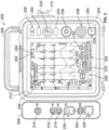
- FIG. 2 illustrates a front view of a medical device 202, in accordance with an example implementation.
- the medical device 202 can comprise the medical device 102 of FIG. 1 .
- the medical device 202 may be configured to monitor and provide treatment or care to a person or patient experiencing a medical condition, such as cardiac arrest or any other cardiac rhythm abnormality.
- the medical device 202 may be operated by a user (e.g., a medical professional, a first responder, a healthcare professional, service worker, a doctor, etc.) and may be used in a hospital or a pre-hospital environment or setting.
- the medical device 202 may be a monitor defibrillator, which is a combination of a monitor and a defibrillator.
- the medical device 202 may be configured to deliver an electrical pulse or shock to a person experiencing a medical condition.
- the medical device 202 may be configured to operate or function in one or more defibrillation modes, such as a manual defibrillation mode, an AED mode, or any other suitable defibrillation mode.
- the medical device 202 may be selected to operate in an AED mode when the medical device 202 is intended to be used by a first responder and/or a layperson who may have no or minimal training in providing medical treatment using defibrillation.
- the medical device 202 may determine whether a defibrillation pulse or shock is needed and, if so, charge an energy storage device (e.g., a capacitor) of the medical device 202 to a predetermined energy level and instruct the user to administer the defibrillation shock.
- the medical device 202 may also be selected to operate in a manual defibrillation mode when the medical device 202 is intended to be used by persons who are trained to provide medical treatment using defibrillation (e.g ., medical professionals, such as doctors, nurses, paramedics, emergency medical technicians, etc.).
- the medical device 202 is configured to operate in the manual defibrillation mode, the user may determine whether a defibrillation pulse or shock is needed and may control the administration of the defibrillation shock to the person.
- the medical device 202 may monitor and evaluate physiological parameters of a person being treated for a medical condition.
- the medical device 202 may receive signals or voltages from one or more electrodes or sensors placed at various locations on the body of the person.
- the electrodes or sensors may sense or detect the physiological parameters of the person and produce signals representative of the physiological parameters.
- the representations of the physiological parameters may be displayed by the medical device 202 to assist a user in treating and diagnosing medical conditions of a person.
- the physiological parameters may include ECG (electrocardiogram) data, body temperature, non-invasive blood pressure (NIBP), arterial oxygen saturation/pulse oximetry (SpO2), a concentration or partial pressure of carbon dioxide in the respiratory gases (e.g., capnography), and/or any other suitable physiological parameter of a person.
- ECG electrocardiogram
- NIBP non-invasive blood pressure
- SpO2 arterial oxygen saturation/pulse oximetry
- concentration or partial pressure of carbon dioxide in the respiratory gases e.g., capnography
- capnography e.g., capnography
- aspects of the treatment being provided may include a depth or recoil amount of a chest compression, or a parameter reflective of the adequacy/security of an airway that has been established to oxygenate and ventilate a patient (such as adequate mask seal).
- aspects of the environment may include motion (e.g . vehicle motion or patient motion).
- Actions and/or status of the provider may include detection of fatigue during performance of chest compressions ( e.g .
- an algorithm may integrate various dimensions of measured chest compression quality into an index indicative of potential fatigue, and the algorithm may be configured to alert the team to this developing fatigue via an audio font, allowing perception of the information without the need to see and/or watch a monitor screen, or experience additional sonic/cognitive clutter from voice prompts or similar warnings delivered via different modalities), or audio-font-mediated feedback on the progress of an intubation attempt wherein a video laryngoscope is being used to execute the procedure, and a real-time algorithm (e.g.
- a computer-vision AI algorithm is being run on the video data, generating real-time feedback on the provider's navigation of the tip of the laryngoscope blade through the succession of anatomic reference points or waypoints towards obtaining visualization of the vocal cords.
- the audio font can change (in either a binary or proportional manner) to communicate deviation from the apparent optimal course as determined by this "decision assist" feature.
- the input module 208 of the medical device 202 may be coupled to or integral with the housing 204.
- the input module 208 may enable the medical device 202 to receive physiological parameters (e.g ., a heart rate (HR) and ECG data) of a person via sensors ( e.g ., the sensors 118 of FIG. 1 ).
- the sensors may be placed on the body of a person to sense or detect signals generated by the body or heart of the person.
- the input module 208 may include one or more ports or receptacles to enable the sensors to be detachably coupled to the input module 208. As shown in FIG.
- the input module 208 can include a port 214 configured to be connected to an oxygen saturation (SpO2) sensor, a port 216 configured to be connected to a temperature sensor, a port 218 configured to be connected to a sensor for measuring invasive blood pressure (IP) via a catheter, a port 220 configured to be connected to a sensor for measuring partial pressure of carbon dioxide (CO2) in gases in the airway via capnography, and a port 222 configured to be connected to a sensor for measuring a non-invasive blood pressure (NIBP).
- the input module 208 may also include a communication port 224, such as a Universal Serial Bus (USB) port, that can be used to connect to an input device (e.g., a mouse, a keyboard, etc.).
- the input module 208 may include other ports to enable any other suitable physiologic parameter of a person to be monitored and evaluated by the medical device 202.
- the defibrillation interface 210 of the medical device 202 may be configured to enable electrical charges or pulses to be delivered or applied to a person via defibrillation electrodes (e.g ., the defibrillation electrodes 110 and 112 shown in FIG. 1 ).
- the defibrillation electrodes may also be configured to enable the medical device 202 to receive physiological parameters of a person (e.g., a heart rate (HR), ECG data, etc.).
- the defibrillation interface 210 may include one or more ports or receptacles capable of allowing the defibrillation electrodes to be detachably coupled to the defibrillation interface 210.
- a cable assembly or therapy cable may enable the defibrillation electrodes to be coupled to the ports of the defibrillation interface 210.
- Each therapy cable may include a defibrillation electrode attached at one end and a connector attached to the other end.
- the connector may be configured to be coupled to or plugged into a port or receptacle of the defibrillation interface 210.
- the user interface 212 of the medical device 202 includes a power button 228 configured to turn the medical device 202 on and off (e.g., "On-Off" button), a charge button 230 configured to cause the medical device 202 to build an electric charge to be applied to the person in a form of a defibrillation shock or pulse, a defibrillation shock button 232 configured to cause the medical device 202 to apply a defibrillation pulse or therapy shock to a person during a defibrillation episode, an analyze button 234 configured to cause the medical device 202 to analyze physiologic parameters of a person (e.g., ECG data) to facilitate determining the appropriate time to apply a defibrillation pulse or shock, and a speed dial button 236 configured to navigate through menus of on-screen software.
- a power button 228 configured to turn the medical device 202 on and off (e.g., "On-Off" button)
- a charge button 230 configured to cause the medical device
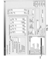
- the medical device 202 may be configured to display a graphical user interface (GUI) 226 that includes graphical elements representative of one or more aspects of analyzed measurement data.
- GUI graphical user interface
- the user interface 212 of the medical device 202 may include a display device 225 (e.g., a touchscreen) for displaying GUI 226.
- the GUI 226 may display physiologic parameters of a person (e.g., a patient), provide visual feedback to the user (e.g., a healthcare provider) about a condition of the person, provide information about the medical device 202 (e.g., battery information), and allow the user to interact with and operate the medical device 202.
- the GUI 226 includes graphical representations of a first battery unit indicator 242 and a second battery unit indicator 244.
- the first battery unit indicator 242 and second battery unit indicator 244 are configured to display a status of a first battery unit and a status of a second battery unit, respectively, of the medical device 202.
- the first and second battery unit indicators 242 and 244 may provide a charging level of the first and second battery units.
- the GUI 226 of the medical device 202 may also allow a user to input a time period for performing a cardiac or resuscitation treatment, such as a CPR time period for performing a CPR treatment.
- a CPR time period for performing a CPR treatment may allow a user to input or select a CPR time period for performing a CPR treatment from preset or predetermined time limits.
- the GUI 226 may display user-selectable user-interface items 256 to allow a user to input or select the CPR time periods.
- the GUI 226 may include the following user-selectable user-interface items: "15 seconds", "1 minute, "2 minutes", and "3 minutes”.
- the GUI 226 may provide signals and prompts to assist a user or rescuer for delivering the medical treatment in accordance with modified sonifications.
- the GUI 226 of the medical device 202 may provide distinct timbral and intensity signatures that may be applied at clinically-meaningful measurement thresholds (e.g ., SpO2 value thresholds) to more clearly indicate to a user that measurement values (e.g., SpO2 values) are not only changing, but have crossed a critical threshold.
- clinically-meaningful measurement thresholds e.g ., SpO2 value thresholds
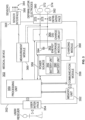
- FIG. 3 is a diagram showing components of a medical device 302, in accordance with an exemplary embodiment.
- the medical device 302 includes a processing unit 350, a memory unit 352, a user interface 354, a communication module or interface 356, a power source 358, a charging module 360, an energy storage module or device 362, a discharge circuit 364, a measurement module 366, a sensor interface 368, and a defibrillator interface 370.
- These components can be, for example, included in the medical devices of Figures 1 or 2 .
- the defibrillation interface 370 of the medical device 302 may be configured to enable an electrical pulse or shock to be delivered or applied to a person ( e.g., a patient) experiencing a medical condition.
- the defibrillation interface 370 may comprise the defibrillation interface 210 of FIG. 2 .
- the defibrillation interface 370 may include one or more ports or nodes 376 and 378 to enable the defibrillation electrodes 372 and 374 to be detachably coupled to the defibrillation interface 370.
- a cable assembly or therapy cable 380 may enable the defibrillation electrode 372 to be coupled to the port 376 of the defibrillation interface 370 and a cable assembly or therapy cable 382 may enable the defibrillation electrode 374 to be coupled to the port 378 of the defibrillation interface 370 of the medical device 302.
- the cable assembly 380 may include the defibrillation electrode 372 attached at one end and a connector attached to the other end, and the cable assembly 380 may include the defibrillation electrode 374 attached at one end and a connector attached to the other end.
- the connectors of the cable assemblies 380 and 382 may be configured to be coupled to or plugged into the ports 376 and 378 of the defibrillation interface 370.
- the connectors can be male or female connectors that are compatible with the ports 376 and 378 of the defibrillation interface 370 of the medical device 302.
- the defibrillation interface 370 may also enable the medical device 302 to receive physiological parameters (e.g ., HR, ECG) of the person or patient.
- physiological parameters e.g ., HR, ECG
- each of the defibrillation electrodes 372 and 374 may be configured to measure one or more physiological parameters of the person (e.g ., heart electrical activity, heart rate, etc.) and to provide signals representative of the physiological parameters to the defibrillation interface 370.
- physiological parameters of the person e.g ., HR, ECG
- each of the defibrillation electrodes 372 and 374 may be configured to measure one or more physiological parameters of the person (e.g ., heart electrical activity, heart rate, etc.) and to provide signals representative of the physiological parameters to the defibrillation interface 370.
- an ECG signal of the person can be detected as a voltage difference between the defibrillation electrodes 372 and 374.
- the defibrillation electrodes 372 and 374 may also be used to determine device parameters indicative of a condition of the medical device 302, such as an electrode impedance or a user interaction with the medical device 302.
- the medical device 302 can detect an impedance between the defibrillation electrodes 372 and 374 to determine whether the defibrillation electrodes 372 and 374 are making sufficient electrical contact with a person's body.
- the sensor interface 368 of the medical device 302 may be configured to receive physiological parameters (e.g ., a heart rate (HR) and ECG data) from one or more sensors 384 (e.g ., physiological sensors).
- the sensors 384 may be placed in contact with the body of a person being monitored or treated for a medical condition.
- Each of the sensors 384 may include a transducer configured to sense a signal or voltage of the person.
- the sensors 384 may measure or detect heart electrical activity and other parameters, such as an electrocardiogram (ECG), saturation of the hemoglobin in arterial blood with oxygen (SpO2), carbon monoxide (carboxyhemoglobin, COHb) and/or methemoglobin (SpMet TM ), partial pressure of carbon dioxide (CO2) in gases in the airway by means of capnography, total air pressure in the airway, flow rate or volume of air moving in and out of the airway, blood flow, blood pressure (e.g ., non-invasive blood pressure (NIBP)), core body temperature with a temperature probe in the esophagus, oxygenation of hemoglobin within a volume of tissue (rSO2), and any other physiological parameters of a person being monitored or treated.
- ECG electrocardiogram
- SpO2 saturation of the hemoglobin in arterial blood with oxygen
- COHb carbon monoxide
- SpMet TM methemoglobin
- CO2 partial pressure of carbon dioxide
- NIBP non-invasive blood pressure
- the sensor interface 368 may include one or more receptacles or ports (e.g., an ECG port) to enable the sensors 384 to be detachably coupled to the medical device 302.
- the sensors 384 may be attached to the sensor interface 368 by cable assembles or therapy cables 386.
- the sensors 384 may be fixedly connected to the sensor interface 368.
- the therapy cables 386 may each include a sensor 384 at one end and a connector at the opposite end. The connector can be configured to be coupled to or plugged into a port or receptacle of the sensor interface 368.
- the measurement module 366 of the medical device 302 may be configured to receive signals or sensor data from the sensor interface 368 and the defibrillation interface 370.
- the signals may be representative of physiological parameters or conditions of a person being monitored and/or treated for a medical condition.
- the measurement module 366 may measure or determine various physiological parameters from the signals. For example, the measurement module 366 may determine an ECG of the person based on a voltage difference between the defibrillation electrodes 372 and 374.
- the measurement module 366 may also determine device parameters indicative of a condition of the medical device 302, such as an electrode impedance or a user interaction with the medical device 302. For example, the measurement module 366 may measure an impedance or voltage across the defibrillation electrodes 372 and 374 or a pair of sensors 384.
- the measurement module 366 may also include a filter circuit or hardware (e.g ., amplifiers, filters, etc.) to attenuate and/or filter at least some of the noise that may be present on the signals received from the sensor interface 368 and/or the defibrillation interface 370.
- the filter circuit may apply at least one filter to the signal to remove artifacts resulting from chest compressions being delivered to the person.
- the filter may be implemented as an analog filter, a digital filter, or combinations of both.
- the measurement module 366 may also digitize the signals received from the sensor interface 368 and/or defibrillation interface 370 prior to transmitting the signals to the processing unit 350.
- the user interface 354 of the medical device 302 may facilitate user interactions with the medical device 302.
- the user interface 314 may comprise the GUI 226 of FIG. 2 .
- the user interface 354 may include various types of input devices for receiving inputs or commands from a user.
- the input devices may include keyboards, switches, microphones, pushbuttons, touchscreens, scanners, and/or any other suitable input device for enabling inputs to the medical device 302.
- a user can use the input devices on the user interface 354 to input information regarding a particular event (e.g., a treatment or medication administered to the person).
- the input devices of the user interface 354 may also allow a user or rescuer to input information (e.g ., parameters, variables, etc.) for enabling the medical device 302 to emit distinct timbral and/or intensity signatures that may be applied at clinically-meaningful measurement thresholds (e.g ., SpO2 value thresholds) to more clearly indicate to a user that measurement values (e.g., SpO2 values) are not only changing, but have crossed a critical threshold for a person experiencing a medical condition, such as cardiac arrest.
- clinically-meaningful measurement thresholds e.g ., SpO2 value thresholds
- the user devices of the user interface 354 may allow the user to input or select an age classification of a person (e.g., adult or child/infant), an airway status (e.g., whether the person has their airway secured by artificial airway), whether the CPR is being delivered by one or two persons, whether the person delivering CPR is a medical professional or a layperson, and values for pitch, timbre and intensity, and/or other variables which may be used by the medical device 102 to select and/or deliver a treatment protocol.
- the medical device 302 may be automatically configured, upon activation or set-up, for an adult with an unsecured airway.
- the input devices of the user interface 354 may also allow the user to input or select a time period for performing a cardiac or resuscitation treatment, such as a CPR time period for performing a CPR treatment.
- a CPR period for the CPR treatment from preset or predetermined time limits (e.g., 15 seconds, 1 minute, 2 minutes, 3 minutes, etc.).
- the medical device 302 may determine or select, based on the user inputs, a CPR treatment protocol from memory (e.g., the memory unit 352).
- the medical device 302 may evaluate the CPR treatment protocol for the CPR treatment. Based on the evaluation, the medical device 302 may modify the CPR treatment protocol and/or may modify or adjust the CPR time period inputted or selected by the user for the CPR treatment as further described below.
- the user interface 354 may also comprise various types of output devices for providing information to the user.
- the output devices may provide instructions or prompts to assist a user or rescuer for delivering CPR treatments to a person experiencing a medical condition, such as cardiac arrest.
- the output devices of the user interface can be visual, audible or tactile for communicating to or providing feedback to a user ( e.g. a rescuer, a first responder, a healthcare professional, etc.).
- the output devices may include a screen, a display, one or more light emitting diodes (LEDs), and/or a speaker to output various sounds (e.g ., voice or audio), etc.
- LEDs light emitting diodes
- the output devices may be configured to present visual alarms or alerts, flashing lights, and/or warnings to the user of the medical device 302.
- the output devices may also include an audio system that provides an audio signal to aurally communicate with user voice prompts that deliver instructions or commands, monotonal, ascending, descending or quickening tones to indicate alerts or warnings, and/or any other suitable output device for communicating with the user.
- the output devices of the user interface 354 may include a metronome or a metronome system for providing signals to guide the user in pacing and timing of chest compressions for cardiac or resuscitation treatments (e.g ., a CPR treatment) and, in some implementations, for providing signals to guide in the pacing and timing of ventilations for the a cardiac or resuscitation treatment.
- the signals may be visual (such as flashing lights or graphics on a display screen), or may he aural.
- the device may include one or more measurement modes, wherein each measurement mode of the one or more measurement modes is associated with a corresponding range of measurement values.
- Such embodiments may involve mapping, for each measurement mode, the corresponding range of measurement values in terms of the intervals of musical notes, identifying, for each measurement mode, a plurality of intervals for the corresponding range of measurement values, and associating, for each measurement mode, a respective plurality of audible fonts with the corresponding plurality of intervals.
- the metronome may deliver to the user a first type of signal for chest compressions, a second type of signal for ventilations, and a third type of signals to indicate an upcoming transition from compressions to ventilations (or, in a protocol where ventilations are given without a pause in compressions, to indicate an upcoming ventilation series).
- the different signal types may be distinguishable from one another by the user. When flashing lights are used, different colors may distinguish between compressions, transitions, and ventilations.
- the aural signals may be any of a variety of sounds such as tones, beeps, tocks, clicks, and the like, or may be voiced (for example, "press-press-press” for compressions, "ventilate” or "blow” for ventilations).
- the signals for chest compressions may be rhythmic signals such as a series of identical sounds delivered at a rate corresponding to the desired rate for chest compressions.
- a sound that is suggestive of or approximates the sound of ventilation may be used for a ventilation signal.
- the sound signal used for each ventilation may have a duration that corresponds to the desired duration of the ventilation.
- the ventilation sound signals may also be delivered at a rate equal to the desired rate for ventilation delivery.
- the transition signals may advise the user that a transition from chest compressions to ventilations (with or without a pause in chest compressions) is coming up soon.
- the output devices of the user interface 352 may include a display configured to visually present to the user various measured or calculated parameters associated with a person or patient experiencing a medical condition, such as cardiac arrest.
- the display can be configured to visually present an ECG and/or other physiological signals indicating the physical status of the person in cardiac arrest.
- the output devices may also provide instructions and/or commands, including prompts to perform CPR treatments or other treatments, to the user.
- the memory unit 352 of the medical device 302 may be in operable communication with the processing unit 350.
- the memory unit 352 may store various values, look-up tables, equations, audio and video files, and/or a plurality of audio font protocols that can be read and accessed by the processing unit 350.
- the audio font protocols may vary depending on factors such as age classification of the person experiencing a medical condition (e.g ., adult or child/infant), an airway status (e.g ., whether the person has their airway secured by artificial airway) or other physiologic specific factors that may affect optimal oxygenation levels or thresholds.
- the memory unit 352 can store instructions or computer executable code of software routines that can be retrieved and executed by the processing unit 350.
- the memory unit 352 may include one or more computer-readable storage media that can be read or accessed by the processing unit 350.
- the computer-readable storage media can include volatile and/or non-volatile memory, dynamic random-access memory (DRAM) read-only memory (ROM), random access memory (RAM), magnetic disk storage media, optical storage media, smart cards, flash memory devices, or any other suitable memory.
- DRAM dynamic random-access memory
- ROM read-only memory
- RAM random access memory
- magnetic disk storage media magnetic disk storage media
- optical storage media smart cards
- flash memory devices or any other suitable memory.
- the computer-readable storage media can be integrated in whole or in part with the processing unit 350.
- the computer-readable storage media may be implemented using a single physical device (e.g., one optical, magnetic, organic or other memory or disc storage unit), while in other examples, the computer readable storage media can be implemented using two or more physical
- the processing unit 350 of the medical device 302 may be configured to control various operations of the medical device 302.
- the processing unit 350 may receive inputs from the user and various components of the medical device 302 and may process the inputs to produce outputs that may be stored in the memory unit 352 and/or displayed or communicated via the user interface 354.
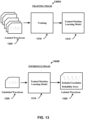
- the processing unit 350 may be configured to perform operations.
- the operations may include analyzing, by a medical device, measurement data collected from the patient.
- the operations may also include associating, by the medical device, a particular audio font based on a characteristic of the measurement data.
- the operations may further include identifying, by the medical device and based on the characteristic of the measurement data, one or more clinically meaningful thresholds in the measurement data.
- the operations may also include generating, by the medical device, an audible change in the particular audio font to reflect whether a particular characteristic of the measurement data has crossed a clinically meaningful threshold of the one or more clinically-meaningful thresholds.
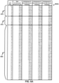
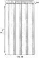
- the processing unit 340 may determine from tables or information stored in the memory unit (e.g., table 900A of FIG. 9A and table 900B of FIG. 9B ) associating a plurality of audible fonts with the corresponding plurality of identified intervals.
- the one or more clinically meaningful thresholds may include a transition of a SpO2 value from a given interval of the plurality of intervals to a next interval of the plurality of intervals.
- the plurality of intervals may include a first interval of SpO2 values from 100% to 94%, a second interval of SpO2 values from 93% to 88%, and a third interval of SpO2 values from 87% to 0%.
- processing unit 350 may also cause appropriate audible fonts to be emitted that indicate whether the waveform representation may be relied upon.
- processing unit 350 may control delivery of other types of treatment therapy to the person via the defibrillation electrodes 372 and 374, such as cardioversion or pacing therapy.
- the communication module 356 of the medical device 302 may be in communication with the processing unit 350.
- the communication module 356 may enable patient data, treatment information, CPR performance, system data, environmental data, etc. to be communicated between the medical device 302 and other devices, such as a remote assistance center and/or any other remote computing device.
- the communication module 356 may include one or more wireless or wireline interfaces that allow for both short-range communication and long range communication to one or more networks or to one or more remote devices.
- the wireless interfaces may provide for communication under one or more wireless communication protocols, such as Bluetooth, Wi-Fi (e.g., an institute of electrical and electronic engineers (IEEE) 802.xx protocol), Long-Term Evolution (LTE), cellular communications, near-field communication (NFC), radio-frequency identification (RFID), and/or other wireless communication protocols.
- wireless communication protocols such as Bluetooth, Wi-Fi (e.g., an institute of electrical and electronic engineers (IEEE) 802.xx protocol), Long-Term Evolution (LTE), cellular communications, near-field communication (NFC), radio-frequency identification (RFID), and/or other wireless communication protocols.
- wireline interfaces may include an Ethernet interface, USB interface, or similar interface to communicate via a wire, a twisted pair of wires, a coaxial cable, an optical link, a fiber-optic link, or other physical connection to a wireline network.
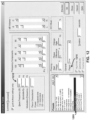
- FIG. 4 illustrates a GUI 402, in accordance with an example implementation.
- the GUI 402 can be displayed by a medical device, such as the medical devices of Figures 1-3 .
- the GUI 402 may be configured to allow a user or rescuer to input information (e.g ., parameters, variables, etc.) for enabling the medical device to select a cardiac or a resuscitation treatment (e.g., a CPR treatment) for a person experiencing a medical condition.
- information e.g ., parameters, variables, etc.
- a resuscitation treatment e.g., a CPR treatment
- the GUI 402 includes a status bar 410, a messaging area 412, a content area 416, and a navigation task bar 418.
- the messaging area 412 of the GUI 402 may display messages and information to the user or rescuer.
- the content area 416 of the GUI 402 may show patient data including physiologic parameters and waveforms output or displayed by the medical device as well as provided by physiologic sensors.
- the content area 416 can include multiple channels, including a primary channel 420 for displaying a primary waveform 430 and multiple secondary channels 422 for displaying secondary data, such as a secondary waveform 432. Although multiple secondary channels 422 are shown, in other examples, a GUI may only display a single secondary channel.
- the GUI 402 may also be configured to display waveforms next to a side rectangle having a particular color and labelled by a physiologic parameter to which the waveform pertains.
- the GUI includes the waveform 430 for heart rate (HR), the waveform 432 for End-tidal CO2 (EtCO2), which indicates the partial pressure or maximal concentration of carbon dioxide (CO2) at the end of an exhaled breath, and the waveform 434 for SpO2.
- the GUI can also display NIBP values for a patient or person being monitored and/or treated.
- the GUI 402 may display a navigation task bar 418 at the bottom of the GUI 402.
- FIG. 5 is an example graph illustrating SpO2 values, in accordance with an example implementation.
- the graph 500 demonstrates how close in frequency SpO2 values from 90 to 100% sound. Barely 50 Hz separates 90 from 100%. Such 5 Hz increments are insufficient for reliable audible discrimination in this sub octave interval.
- a typical approach involves formulating a linear equation relating sound pitch to some displayed value. For example, pulse oximeters that provide pulse tones of variable pitch dependent on the measured oxygen saturation typically use a linear mapping between oxygen saturation and the sonic frequency of the pulse tone. In this scheme, the entire 100% to 0% range of possible oxygen saturation values is mapped across a range of approximately two musical octaves.
- Pythagoras determined appropriate musical scales in the 6th century BC based on the logarithmic behavior of the Human Auditory System (HAS).
- HAS Human Auditory System
- Musical notes used in western music are constructed using a ratio of 2 12 between notes.
- the 88 keys on a piano are not enough to represent the 100 notes required for SpO2 values.
- the 88 keys span a frequency range that exceeds a capacity for small speakers typically used in portable medical devices. For example, a typical 50 mm speaker has a frequency response of 350 to 5000 Hz between lower and upper resonance while the piano spans 29.135 to 4186 Hz for fundamentals of each key.
- the characteristic of the measurement data includes a magnitude of a value of the measurement data.
- the measurement data may be associated with a corresponding range of measurement values.
- Some embodiments involve mapping the range of measurement values in terms of intervals of musical notes.
- a typical approach by non-audio oriented engineers involves formulating a linear equation relating sound pitch to some displayed value.
- FIG. 6 is a comparison 600 of a scaled graph 605 and a linear graph 610 for SpO2 values, in accordance with an example implementation.
- the device includes a pulse oximeter displaying SpO2 values in a range from 0-100%. While the linear mapping scheme of saturation to sonic frequency may be reasonable in some monitoring situations, it can be suboptimal, and even potentially hazardous, during certain emergency care procedures. For example, patients undergoing rapid sequence intubation (RSI) are at high risk for precipitous oxygen desaturation. An inability to promptly detect and correct such desaturation can result in significant patient harm including cardiac arrest.
- RSI rapid sequence intubation
- the intervals of musical notes correspond to a ratio of 2 36 between successive notes.
- the scaled (logarithmic) graph 605 depicts a scale based on ratio of 2 36 compared to the linear graph 610.
- the two graphs 605 and 610 intersect at point 615 that corresponds to a SpO2 value of 61%. Greater separation of frequency exists at 61% and above on the linear graph 610 while switching to the scaled graph 605 below 61% provides an advantage of moving the lowest frequencies required to a higher value.
- Below 38% audible detection is reliant upon second and higher harmonics introduced to the tones.
- Sine waves with a psycho-acoustically designed second, third, and fifth harmonic structure may be utilized for audibility in noisy environments. Square waves may generally waste energy on the sixth and higher harmonics, and are not useful for tone audibility.
- a linear scale provided by linear graph 610 may be used for the upper pitch starting point (e.g., SpO2 100%) of 987.77 Hz above SpO2 of 60%, and a logarithmic scale provided by scaled graph 605 may be used at 60% and below.
- SpO2 100% the upper pitch starting point
- scaled graph 605 may be used at 60% and below.
- Some embodiments may involve a first mapping of the SpO2 values, wherein the first mapping is a linear mapping in terms of intervals of musical notes for SpO2 values below 60%, and a second mapping of the SpO2 values, wherein the second mapping is a logarithmic mapping in terms of intervals of musical notes for SpO2 values above 60%.
- a hybrid approach may involve each 1% change being mapped to an even semi-tone or whole tone change over the range from 100% down to a first threshold, such as a value of e.g. 85%-90%, and the remainder of the range down to 0% being mapped with a different ( e.g . linear) much more gradual mapping.
- a first threshold such as a value of e.g. 85%-90%
- a different (e.g . linear) much more gradual mapping e.g. linear) much more gradual mapping.
- the characteristic of the measurement data may include a magnitude of a value of the measurement data, wherein the particular characteristic comprises a particular value, and wherein the one or more clinically meaningful thresholds comprises one or more threshold values.
- FIG. 7 illustrates an example hybrid pitch scale 700 for SpO2 values, in accordance with an example implementation.
- a hybrid approach can be adopted to fit 100 notes into the limits of the speaker frequency response while enhancing pitch discrimination.
- the existing two octaves of potential pitches may be mapped to the 100% to 0% range of potential oxygen saturation values linearly in terms of musical interval, rather than linearly in terms of sonic frequency. This can facilitate greater perception of oxygen saturation changes at the higher end of the saturation range, where most patients are going to be operating, and where there is a greater need for situational awareness to prevent or rapidly respond to dangerous desaturation during critical procedures like RSI.
- the hybrid approach can involve a piecewise function that includes a first function 705 and a second function 710 that are connected at point 715.
- the point 715 corresponds to a SpO2 value of 60%.
- thirty-nine SpO2 values ranging from 100% to 61% may be fit into approximately one octave with improved auditory discrimination.
- the remaining sixty values below 61% (represented by the first function 705) may be fit into approximately 1.5 octaves and also present improved auditory discrimination.
- this improvement may lack sufficient spread of tones for less musically inclined individuals.
- the plurality of audible fonts may include a first audio font corresponding to the first interval, a second audio font corresponding to the second interval, and a third audio font corresponding to the third interval, and wherein the one or more clinically meaningful thresholds comprises 94% or 88%.
- FIG. 8 illustrates an example dissociation curve 800 for multiple ranges of SpO2 values, in accordance with an example implementation.
- modification of the tone timbre which is referred to as "audible fonts” can increase the ability to audibly identify attributes of interest conveyed in the sonification.
- the oxyhemoglobin dissociation curve 800 illustrates multiple ranges of interest for SpO2 values.
- dissociation curve 800 may be a combination of three curves, a first curve 805 connecting point A (at an SpO2 value of 0%) to point B (at an SpO2 value of 87%), a second curve 810 connecting point B to point C (at an SpO2 value of 93%), and a third curve 815 connecting point C to point D (at an SpO2 value of 100%).
- the first curve 805 represents a range of SpO2 values from 100% to 94%
- the second curve 810 represents a range of SpO2 values from 93% to 88%
- the first curve 805 represents a range of SpO2 values below 87%.
- a first audible font may be applied to the pitches for values represented by the first curve 805
- a second audible font may be applied to pitches for values represented by the second curve 810
- a third audible font may be applied to pitches for values represented by the third curve 815.
- instances in this specification where one element is "coupled" to another element can include direct and indirect coupling.
- Direct coupling can be defined as one element coupled to and in some contact with another element.
- Indirect coupling can be defined as coupling between two elements not in direct contact with each other, but having one or more additional elements between the coupled elements.
- securing one element to another element can include direct securing and indirect securing.
- adjacent does not necessarily denote contact. For example, one element can be adjacent another element without being in contact with that element.
- first, second, etc. are used herein merely as labels, and are not intended to impose ordinal, positional, or hierarchical requirements on the items to which these terms refer. Moreover, reference to, e.g., a “second” item does not require or preclude the existence of, e.g., a "first” or lower-numbered item, and/or, e.g., a "third" or higher-numbered item.
Landscapes
- Health & Medical Sciences (AREA)
- Life Sciences & Earth Sciences (AREA)
- Engineering & Computer Science (AREA)
- Public Health (AREA)
- Medical Informatics (AREA)
- Biomedical Technology (AREA)
- General Health & Medical Sciences (AREA)
- Physics & Mathematics (AREA)
- Pathology (AREA)
- Heart & Thoracic Surgery (AREA)
- Veterinary Medicine (AREA)
- Surgery (AREA)
- Animal Behavior & Ethology (AREA)
- Biophysics (AREA)
- Molecular Biology (AREA)
- Epidemiology (AREA)
- Primary Health Care (AREA)
- Data Mining & Analysis (AREA)
- Databases & Information Systems (AREA)
- Cardiology (AREA)
- Spectroscopy & Molecular Physics (AREA)
- Physiology (AREA)
- Human Computer Interaction (AREA)
- Optics & Photonics (AREA)
- Physical Education & Sports Medicine (AREA)
- Rehabilitation Therapy (AREA)
- Business, Economics & Management (AREA)
- General Business, Economics & Management (AREA)
- Pulmonology (AREA)
- Pain & Pain Management (AREA)
- Emergency Medicine (AREA)
- Nuclear Medicine, Radiotherapy & Molecular Imaging (AREA)
- Urology & Nephrology (AREA)
- Measurement Of The Respiration, Hearing Ability, Form, And Blood Characteristics Of Living Organisms (AREA)
Applications Claiming Priority (1)
| Application Number | Priority Date | Filing Date | Title |
|---|---|---|---|
| US202363615836P | 2023-12-29 | 2023-12-29 |
Publications (1)
| Publication Number | Publication Date |
|---|---|
| EP4579676A1 true EP4579676A1 (fr) | 2025-07-02 |
Family
ID=93923280
Family Applications (1)
| Application Number | Title | Priority Date | Filing Date |
|---|---|---|---|
| EP24219474.4A Pending EP4579676A1 (fr) | 2023-12-29 | 2024-12-12 | Dispositif médical à sonifications modifiables |
Country Status (3)
| Country | Link |
|---|---|
| US (1) | US20250213200A1 (fr) |
| EP (1) | EP4579676A1 (fr) |
| AU (1) | AU2024278283A1 (fr) |
Citations (1)
| Publication number | Priority date | Publication date | Assignee | Title |
|---|---|---|---|---|
| US20190224434A1 (en) * | 2018-01-17 | 2019-07-25 | Zoll Medical Corporation | Systems and methods for assisting patient airway management |
Family Cites Families (6)
| Publication number | Priority date | Publication date | Assignee | Title |
|---|---|---|---|---|
| US10369323B2 (en) * | 2016-01-15 | 2019-08-06 | Robert Mitchell JOSEPH | Sonification of biometric data, state-songs generation, biological simulation modelling, and artificial intelligence |
| US11484247B2 (en) * | 2016-07-01 | 2022-11-01 | Bostel Technologies, Llc | Phonodermoscopy, a medical device system and method for skin diagnosis |
| US20220076077A1 (en) * | 2020-09-04 | 2022-03-10 | Microsoft Technology Licensing, Llc | Quality estimation model trained on training signals exhibiting diverse impairments |
| US12131825B2 (en) * | 2020-11-20 | 2024-10-29 | Carefusion 303, Inc. | Criteria based alarms coordination between a network of medical devices |
| EP4555957A3 (fr) * | 2021-04-16 | 2025-07-16 | Physcade, Inc. | Thérapie personnalisée de la rythm cardiaque |
| US12527931B2 (en) * | 2021-11-01 | 2026-01-20 | Unitedhealth Group Incorporated | Machine learning techniques for optimized breathing therapy |
-
2024
- 2024-12-09 US US18/974,198 patent/US20250213200A1/en active Pending
- 2024-12-11 AU AU2024278283A patent/AU2024278283A1/en active Pending
- 2024-12-12 EP EP24219474.4A patent/EP4579676A1/fr active Pending
Patent Citations (1)
| Publication number | Priority date | Publication date | Assignee | Title |
|---|---|---|---|---|
| US20190224434A1 (en) * | 2018-01-17 | 2019-07-25 | Zoll Medical Corporation | Systems and methods for assisting patient airway management |
Also Published As
| Publication number | Publication date |
|---|---|
| AU2024278283A1 (en) | 2025-07-17 |
| US20250213200A1 (en) | 2025-07-03 |
Similar Documents
| Publication | Publication Date | Title |
|---|---|---|
| US20260090772A1 (en) | System and method for monitoring respiratory rate measurements | |
| US11311230B2 (en) | Medical premonitory event estimation | |
| US20200261029A1 (en) | Patient monitor including multi-parameter graphical display | |
| US8805488B2 (en) | Automated ischemia analysis of ECG data | |
| US20260011439A1 (en) | Systems and methods for on-device real-time access and review of events during a patient treatment episode | |
| US20250331721A1 (en) | Methods and Systems for Patient Parameter Fusion and Feedback | |
| EP4579676A1 (fr) | Dispositif médical à sonifications modifiables | |
| CA3259689A1 (fr) | Dispositif avec des sonifications modifiables | |
| US20240207625A1 (en) | Self-use treatment device | |
| US20240065576A1 (en) | Physiological parameter reliability indicators | |
| US20250248894A1 (en) | Systems, Methods, and Apparatus for Providing Medical Treatment Feedback | |
| US20250248892A1 (en) | Systems, Methods, and Apparatus for Adjusting Medical Treatments | |
| US20250213871A1 (en) | Systems, Methods, and Apparatus for Detecting the End of Life of a Battery | |
| WO2011093919A1 (fr) | Protocole de thérapie configurable par un utilisateur pour ischémie cardiaque aiguë | |
| US20250256119A1 (en) | Systems and Methods for Configurable Defibrillator Displays and Patient Care Reports | |
| CN120284699A (zh) | 基于超声多普勒反馈技术的心脏骤停救治装置 | |
| WO2010096247A1 (fr) | Protocole de thérapie configurable par utilisateur pour ischémie cardiaque aiguë | |
| Doesburg | Mobile Monitoring in Anaesthesia using smartphones |
Legal Events
| Date | Code | Title | Description |
|---|---|---|---|
| PUAI | Public reference made under article 153(3) epc to a published international application that has entered the european phase |
Free format text: ORIGINAL CODE: 0009012 |
|
| STAA | Information on the status of an ep patent application or granted ep patent |
Free format text: STATUS: THE APPLICATION HAS BEEN PUBLISHED |
|
| AK | Designated contracting states |
Kind code of ref document: A1 Designated state(s): AL AT BE BG CH CY CZ DE DK EE ES FI FR GB GR HR HU IE IS IT LI LT LU LV MC ME MK MT NL NO PL PT RO RS SE SI SK SM TR |
|
| STAA | Information on the status of an ep patent application or granted ep patent |
Free format text: STATUS: REQUEST FOR EXAMINATION WAS MADE |
|
| 17P | Request for examination filed |
Effective date: 20251030 |