EP4579708A1 - Structure de commutation reliée électriquement à une source de lumière - Google Patents
Structure de commutation reliée électriquement à une source de lumière Download PDFInfo
- Publication number
- EP4579708A1 EP4579708A1 EP24216886.2A EP24216886A EP4579708A1 EP 4579708 A1 EP4579708 A1 EP 4579708A1 EP 24216886 A EP24216886 A EP 24216886A EP 4579708 A1 EP4579708 A1 EP 4579708A1
- Authority
- EP
- European Patent Office
- Prior art keywords
- sections
- light source
- conducting
- push button
- contact block
- Prior art date
- Legal status (The legal status is an assumption and is not a legal conclusion. Google has not performed a legal analysis and makes no representation as to the accuracy of the status listed.)
- Pending
Links
Images


Classifications
-
- H—ELECTRICITY
- H01—ELECTRIC ELEMENTS
- H01H—ELECTRIC SWITCHES; RELAYS; SELECTORS; EMERGENCY PROTECTIVE DEVICES
- H01H13/00—Switches having rectilinearly-movable operating part or parts adapted for pushing or pulling in one direction only, e.g. push-button switch
- H01H13/02—Details
- H01H13/023—Light-emitting indicators
-
- H—ELECTRICITY
- H01—ELECTRIC ELEMENTS
- H01H—ELECTRIC SWITCHES; RELAYS; SELECTORS; EMERGENCY PROTECTIVE DEVICES
- H01H13/00—Switches having rectilinearly-movable operating part or parts adapted for pushing or pulling in one direction only, e.g. push-button switch
- H01H13/02—Details
- H01H13/12—Movable parts; Contacts mounted thereon
- H01H13/14—Operating parts, e.g. push-button
-
- H—ELECTRICITY
- H01—ELECTRIC ELEMENTS
- H01H—ELECTRIC SWITCHES; RELAYS; SELECTORS; EMERGENCY PROTECTIVE DEVICES
- H01H13/00—Switches having rectilinearly-movable operating part or parts adapted for pushing or pulling in one direction only, e.g. push-button switch
- H01H13/02—Details
- H01H13/04—Cases; Covers
-
- H—ELECTRICITY
- H01—ELECTRIC ELEMENTS
- H01H—ELECTRIC SWITCHES; RELAYS; SELECTORS; EMERGENCY PROTECTIVE DEVICES
- H01H13/00—Switches having rectilinearly-movable operating part or parts adapted for pushing or pulling in one direction only, e.g. push-button switch
- H01H13/50—Switches having rectilinearly-movable operating part or parts adapted for pushing or pulling in one direction only, e.g. push-button switch having a single operating member
- H01H13/503—Stacked switches
-
- H—ELECTRICITY
- H01—ELECTRIC ELEMENTS
- H01H—ELECTRIC SWITCHES; RELAYS; SELECTORS; EMERGENCY PROTECTIVE DEVICES
- H01H2221/00—Actuators
- H01H2221/056—Modular conception
-
- H—ELECTRICITY
- H01—ELECTRIC ELEMENTS
- H01H—ELECTRIC SWITCHES; RELAYS; SELECTORS; EMERGENCY PROTECTIVE DEVICES
- H01H2229/00—Manufacturing
- H01H2229/022—Modular assembly
-
- H—ELECTRICITY
- H01—ELECTRIC ELEMENTS
- H01H—ELECTRIC SWITCHES; RELAYS; SELECTORS; EMERGENCY PROTECTIVE DEVICES
- H01H9/00—Details of switching devices, not covered by groups H01H1/00 - H01H7/00
- H01H9/20—Interlocking, locking, or latching mechanisms
- H01H9/26—Interlocking, locking, or latching mechanisms for interlocking two or more switches
Definitions
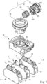
- Fig. 1 shows a commonly seen switch device that includes one single push button for manipulating a plurality of contact blocks assembled to each other.
- the switch device in Fig. 1 includes a single coupling seat 40, which provides a space for coupling three contact blocks 5 thereto.
- Each of the contact blocks 5 is provided with at least one control terminal 51 for connecting with an external device to be controlled.
- the contact blocks 5 are controllable by one push button assembly 20 to operate synchronously, so as to control the external devices to operate.
- a light holder 10 with a light source (not shown) is required to replace one of the contact blocks 5.
- the light holder 10 only provides a relatively simple fixing structure for holding the light source. That is, the light holder 10 only has an electrical contact 101 provided on a surface thereof for connecting to the light source, and there is not any other control structure provided in the light holder 10 for making the light source.
- the control terminal 51 on one of the remaining contact blocks 5 is serially electrically connected to the electrical contact 101 of the light holder 10 before being connected to an external power source.
- the push button assembly 20 is pushed to control the contact blocks 5
- the light source on the light holder 10 is electrically made at the same time to emit light for indicating the operational movement and operational state of the switch device.
- the quantity of the contact blocks that can be used by the switch device to control the external devices is decreased, and the practical application efficiency of the switch device is also reduced.
- the electrical connection between the control terminals 51 on the contact blocks 5 and the electrical contact 101 on the light holder 10 not only influences the internal structural design of the switch device, but also makes the wiring of the switch device more complicated.
- a primary object of the present invention is to provide a switch structure electrically linked with a light source, which includes a main body, a push button assembly, and at least one contact block.
- the main body includes a base provided with a plurality of power terminals for connecting to an external power source, and an internal switch assembly being serially connected to between the power terminals and a light source.
- the contact block includes a plurality of control terminals for connecting to an external device to be controlled.
- the push button assembly is able to drive the internal switch assembly and the contact block, such that the contact block changes an electrical connection state between the control terminals and the internal switch assembly can synchronously control the light source to electrically connect to the external power source. Since the above arrangement does not occupy any contact block that is originally intended for connecting to the external device to be controlled, the switch structure can have overall upgraded usage effectiveness.
- Another object of the present invention is to provide the above switch structure electrically linked with a light source, the internal switch assembly of which includes two fixedly spaced conducting section and an elastic conducting element (such as a torsion spring) located between the two conducting sections.
- the two conducting sections are electrically connected to the power terminals and the light source, respectively.
- the elastic conducting element is driven by the push button assembly to contact with the two conducting sections at the same time or separate from the two conducting sections at the same time, so as to control the connection or disconnection of the light source to or from the power source.
- a further object of the present invention is to provide the above switch structure electrically linked with a light source, the push button assembly of which includes a push button and an actuator electrically connected to each other.
- the actuator can actuate a link member and the contact blocks synchronously to change the electrical connection state between the control terminals of the contact block, so as to control the external device to operate.
- the link member brings the elastic conducting element (torsion spring) of the internal switch assembly to move, enabling the light source to emit light in response to the electrical connection state of the contact block.
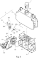
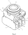
- a first embodiment of the present invention discloses a normally open switch structure, which includes a main body 1 having a substantially rectangular configuration and a push button assembly 2.
- the main body 1 includes a base 11 and an internal switch assembly 13.
- the base 11 internally defines a receiving space 111 for receiving a circuit board 12 therein.
- the circuit board 12 has a plurality of power terminals 121 provided thereon.
- the base 11 can have a cover 14 externally fitted thereon, if necessary.
- the cover 14 is provided with an assembling hole 141, to which a light source 3 is fixedly mounted.
- the power terminals 121 are partially exposed from the cover 14 for a predetermined external power source to connect thereto.
- the internal switch assembly 13 includes two post-like conducting sections 132 spaced from each other by a fixed distance and an elastic conducting element 133, such as a torsion spring, provided between the two post-like conducting sections 132.
- an elastic conducting element 133 such as a torsion spring, provided between the two post-like conducting sections 132.
- One of the two post-like conducting sections 132 is electrically connected to one of the power terminals 121, and the other post-like conducting section 132 is electrically connected to an end of the light source 3, such that the internal switch assembly 13 is serially connected to between the light source 3 and the power terminals 121.
- the elastic conducting element 133 has a middle portion formed into a cylindrical coil body 134, and two elastically bendable conducting arms 135 straightly or obliquely extended from two lateral sides or two ends of the cylindrical coil body 134 toward the two post-like conducting sections 132.
- the elastic conducting element 133 i.e. the torsion spring
- the elastic conducting element 133 can be driven by
- two post-like insulation stop sections 131 may be provided at two lateral outer sides of the two post-like conducting sections 132, if necessary.
- the insulation stop sections 131 are located in front of a moving path of the elastic conducting element 133.
- the two insulation stop sections 131 are respectively located at two lateral outer sides of the two conducting sections 132 and at a higher position than the conducting sections 132.
- the push bottom assembly 2 includes a push button 21, an actuator 22, a push-bottom seat 24, and a link member 25.
- the push button 21 is a structure pervious to light.
- the push button 21 and the actuator 22 are received in the push-button seat 24, and the push-button seat 24 is mounted in a mounting hole 41 on a coupling seat 4.
- the coupling seat 4 is configured to parallelly connect and hold the main body 1 to at least one normally open contact block 5.
- the normally open contact block 5 has a substantially rectangular configuration and is provided with a plurality of control terminals 51, which are connectable to external devices to be controlled, and a push section 52 for controlling the control terminals 51 to an open or a closed circuit.
- the actuator 22 has an end connected to the push button 21 and is accordingly, movable simultaneously with the push button 21. Another end of the actuator 22 is provided with first abutting sections 221 and second abutting sections 222 that are radially spaced from each other relative to a center of the actuator 22. The second abutting sections 222 can correspondingly abut against the push sections 52 of the normally open contact blocks 5.
- An elastic element 23 is fitted between the first and the second abutting sections 221, 222 to press against a top of the main body 1 (i.e. the cover 14), so that the actuator 22 together with the push button 21 has a degree of elasticity to maintain at a non-pushed position.
- the link member 25 includes a coupling section 251 and at least one upward protruded section 252.
- the coupling section 251 is coupled with the cylindrical coil body 134 of the elastic conducting element 133, and the upward protruded section 252 is located corresponding to the first abutting sections 221.
- the two conducting sections 132 are provided on the circuit board 12, which is provided at a position between the two conducting sections 132 with a longitudinally extended guide slot 122.
- the insulation stop sections 131 are provided in the receiving space 111 of the base 11, such that the insulation stop sections 131 are just located at two lateral outer sides of the two conducting sections 132 after the circuit board 12 is assembled to the receiving space 11.
- the link member 25 further includes a sliding guide section 253, which is transversely extended between the coupling section 251 and the upward protruded section 252 to be located and slidable in the sliding guide slot 122, such that the link member 25 can bring the elastic conducting element 133 to move along a longitudinal path between the two conducting sections 132.
- the actuator 22 when the push button 21 is in a natural state without being downward pushed, the actuator 22 is supported by the elastic element 23 and located at a position spaced from the link member 25, and the link member 25 is not in contact with the push sections 52 of the normally open contact blocks 5. Therefore, the two control terminals 51 maintain at the electrically disconnected state, and the external device connected to the two control terminals 51 is in a disabled state. Meanwhile, the insulation stop sections 131 are abutted against the two straight conducting arms 135 of the elastic conducting elements 133, such that the two conducting sections 132 are in a pressure preloaded condition and could not contact with and electrically connect to the two conducting arms 135. Therefore, the light source 3 is not electrically connected to the external power source and could not emit light, as shown in Fig. 6 .
- Figs. 7 and 8 Please refer to Figs. 7 and 8 for the operation of the first embodiment of the present invention.
- the actuator 22 is brought by the push button 21 to move downward at the same time to compress the elastic element 23.
- the first abutting sections 221 are pressed against the upward protruded section 252 of the link member 25 and the second abutting sections 222 are pressed against the push sections 52 of the normally open contact blocks 5.
- the two control terminals 51 are simultaneously electrically connected.
- the link member 25 brings the elastic conducting element 133 to move along the guide slot 122 toward the two conducting sections 132.
- the two conducting arms 135 would first contact with the insulation stop sections 131 to be elastically bent before they contact with both the insulation stop sections 131 and the conducting sections 132, as shown in Fig. 7 .
- the elastic conducting element 133 is in a bent state and the two conducting arms 135 are in initial or non-stable contact with the two conducting sections 132.
- the push button 21 is continuously downward pushed, the two conducting arms 135 of the elastic conducting element 133 are restricted between the two conducting sections 132 to be bent further and finally separate from the two insulation stop sections 131.
- the two conducting arms 135 are in stable contact with only the two conducting sections 132, and the two conducting sections 132 become electrically connected via the elastic conducting element 133 to close a circuit between the light source 3 and the external power source, so that the light source 3 is lighted, as shown in Fig. 8 .
- the two insulation stop sections 131 are located in front of the moving path along which the elastic conducting element 133 is moved toward the conducting sections 132. With this arrangement, it is able to ensure the two conducting arms 135 would not contact with the two conducting sections 132 when the push button 21 is not pushed down and to avoid incorrect conduction. Further, when the push button 21 is downward pushed, the two insulation stop sections 131 can serve as an aid to first turn the two conducting arms 135, so that the two conducting arms 135 can contact with the two conducting sections 132 mildly and smoothly with a somewhat small force to avoid the two conducting sections 132 from bending and deforming due to a sudden strong force applied thereto.
- the normally closed switch structure in the second embodiment includes a main body 1, a push button assembly 2, and a coupling seat 4.
- the push button assembly 2 and the coupling seat 4 are the same as those in the first embodiment.
- the main body 1 includes an internal switch assembly 13, a base 11, a circuit board 12, and power terminals 121.
- the base 11, the circuit board 12, and the power terminals 121 are the same as those in the first embodiment.
- the second embodiment is different from the first one in that the coupling seat 4 is configured for fixedly connecting the main body 1 and at least one normally closed contact blocks 50 in parallel, and each normally closed contact block 50 is provided with a plurality of control terminals 501 for connecting to an external device to be controlled and a push section 52 for controlling the electrical connection or disconnection of the control terminals 501.
- the internal switch assembly 13 includes two post-like conducting sections 132 spaced from each other by a fixed distance, two post-like insulation stop sections 131 provided between the two conducting sections 132, which are connected to between the light source 3 and the power terminals 121 in series, and an elastic conducting element 133, such as a torsion spring.
- the elastic conducting element 133 includes a middle portion formed into a cylindrical coil body 134, which is connected to a link member 25 of the push button assembly 2 to move along with the push button 21, and two elastically bendable conducting arms 135 extended from two lateral sides of the cylindrical coil body 134 toward the two conducting sections 132.
- the insulation stop sections 131 are located in front of a moving path of the elastic conducting element 133. For example, as shown in Fig. 11 , the two insulation stop sections 131 are located between and lower than the two conducting sections 132.
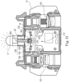
- Figs. 12 and 13 Please refer to Figs. 12 and 13 for the operation of the second embodiment of the present invention.
- the actuator 22 is brought by the push button 21 to move downward at the same time to compress the elastic element 23.
- the first abutting sections 221 are pressed against the upward protruded section 252 of the link member 25 and the second abutting sections 222 are pressed against the push sections 52 of the normally closed contact blocks 50.
- the push sections 52 are pressed by the second abutting sections 222, the two control terminals 501 are electrically disconnected from each other.
- the external device electrically connected to the two control terminals 501 is in an open circuit and disabled state.
- the link member 25 brings the elastic conducting element 133 to slide along the guide slot 122 toward the two insulation stop sections 131. Since the two conducting arms 135 contact with the two conducting sections 132 first, the two conducting arms 135 are elastically bent to touch the two insulation stop section 131, as shown in Fig. 12 . At this point, the elastic conducting element 133 is in an initially bent position, and the two conducting arms 135 are in unstable contact with the two conducting sections 132. When the push button 21 is continuously downward pushed, the two conducting arms 135 of the elastic conducting element 133 are restricted between the two insulation stop sections 131 and bent further to finally separate from the two conducting sections 132 to contact only with the two insulation stop sections 131. At this point, the two conducting sections 132 are electrically disconnected from each other, and the light source 3 is not able to electrically connect to the external power source and accordingly, could not emit light, as shown in Fig. 13 .
- the elastic conducting element 133 such as a torsion spring, has a middle portion formed into a cylindrical coil body 134 for coupling with and moving along with the link member 25 of the push button assembly 2, and two elastically bendable conducting arms 135 extended from two lateral sides of the cylindrical coil body 134 toward the two conducting sections 132 and the two conducting sections 132a.
- the two conducting arms 135 of the elastic conducting element 133 respectively maintain at a straight position to contact with and electrically connect to the two second conducting sections 132a, and the pins of the light source 3a corresponding to one color light, such as red color light, are electrically connected to the external power source, so that the light source 3a emits light, as shown in Fig. 15 , indicating the push button assembly 2 and the main body 1a are in a control state to control the external device to perform a specific operation.
Landscapes
- Push-Button Switches (AREA)
- Switch Cases, Indication, And Locking (AREA)
Applications Claiming Priority (1)
| Application Number | Priority Date | Filing Date | Title |
|---|---|---|---|
| TW112151592A TWI890252B (zh) | 2023-12-29 | 2023-12-29 | 可連動燈源之開關結構 |
Publications (1)
| Publication Number | Publication Date |
|---|---|
| EP4579708A1 true EP4579708A1 (fr) | 2025-07-02 |
Family
ID=93743865
Family Applications (1)
| Application Number | Title | Priority Date | Filing Date |
|---|---|---|---|
| EP24216886.2A Pending EP4579708A1 (fr) | 2023-12-29 | 2024-12-02 | Structure de commutation reliée électriquement à une source de lumière |
Country Status (3)
| Country | Link |
|---|---|
| US (1) | US20250218706A1 (fr) |
| EP (1) | EP4579708A1 (fr) |
| TW (1) | TWI890252B (fr) |
Citations (4)
| Publication number | Priority date | Publication date | Assignee | Title |
|---|---|---|---|---|
| EP0342703A2 (fr) * | 1988-05-19 | 1989-11-23 | Omron Tateisi Electronics Co. | Commutateur à bouton-poussoir lumineux |
| EP0226733B1 (fr) * | 1985-11-05 | 1991-08-21 | Firma Georg Schlegel | Touche de commande avec construction sous forme d'éléments en disque |
| EP1152441B1 (fr) * | 1999-11-10 | 2009-07-29 | Idec Izumi Corporation | Piece electrique et systeme d'arret d'urgence et dispositif de communication comportant cette piece |
| EP2400608B1 (fr) * | 2010-06-26 | 2018-11-14 | Eaton Industries GmbH | Appareil de communication de fabrication modulaire pour mise en réseau et signalisation avec appareils de commande et de signalisation |
Family Cites Families (6)
| Publication number | Priority date | Publication date | Assignee | Title |
|---|---|---|---|---|
| JP4061347B2 (ja) * | 2003-08-05 | 2008-03-19 | 株式会社キャットアイ | 照明装置 |
| TW200917582A (en) * | 2007-10-05 | 2009-04-16 | Lotes Co Ltd | An electrical connecting apparatus |
| US8348478B2 (en) * | 2010-08-27 | 2013-01-08 | Tyco Electronics Nederland B.V. | Light module |
| CN203024104U (zh) * | 2012-12-04 | 2013-06-26 | 海立电气股份有限公司 | 具发光二极管的开关模块 |
| CN203963600U (zh) * | 2014-07-02 | 2014-11-26 | 四川华泰电气有限公司 | 一种led防爆应急灯 |
| CN205782141U (zh) * | 2015-05-19 | 2016-12-07 | 嘉兴山蒲照明电器有限公司 | Led日光灯 |
-
2023
- 2023-12-29 TW TW112151592A patent/TWI890252B/zh active
-
2024
- 2024-11-12 US US18/944,336 patent/US20250218706A1/en active Pending
- 2024-12-02 EP EP24216886.2A patent/EP4579708A1/fr active Pending
Patent Citations (4)
| Publication number | Priority date | Publication date | Assignee | Title |
|---|---|---|---|---|
| EP0226733B1 (fr) * | 1985-11-05 | 1991-08-21 | Firma Georg Schlegel | Touche de commande avec construction sous forme d'éléments en disque |
| EP0342703A2 (fr) * | 1988-05-19 | 1989-11-23 | Omron Tateisi Electronics Co. | Commutateur à bouton-poussoir lumineux |
| EP1152441B1 (fr) * | 1999-11-10 | 2009-07-29 | Idec Izumi Corporation | Piece electrique et systeme d'arret d'urgence et dispositif de communication comportant cette piece |
| EP2400608B1 (fr) * | 2010-06-26 | 2018-11-14 | Eaton Industries GmbH | Appareil de communication de fabrication modulaire pour mise en réseau et signalisation avec appareils de commande et de signalisation |
Also Published As
| Publication number | Publication date |
|---|---|
| TWI890252B (zh) | 2025-07-11 |
| US20250218706A1 (en) | 2025-07-03 |
| TW202526226A (zh) | 2025-07-01 |
Similar Documents
| Publication | Publication Date | Title |
|---|---|---|
| US6858812B2 (en) | Push-button switch | |
| US6773283B2 (en) | Switchable connector device | |
| EP1760836B1 (fr) | Connecteur électrique pour un cable plat | |
| US6784382B2 (en) | Push-on switch | |
| US4017700A (en) | Modular printed circuit board mountable push-button switch with tactile feedback | |
| EP1378966A1 (fr) | Connecteur électrique pour conducteur plat | |
| US7122756B2 (en) | Push switch | |
| US20030234169A1 (en) | Push-button switch | |
| US4585914A (en) | Miniature push-button switch | |
| US5803240A (en) | Electric push-button switch | |
| US6984796B2 (en) | Electrical switch assembly | |
| JPH076648A (ja) | 電気スイッチ組立体 | |
| EP4579708A1 (fr) | Structure de commutation reliée électriquement à une source de lumière | |
| US6841751B2 (en) | Switching device | |
| US9024215B2 (en) | Switch device | |
| EP0336797B1 (fr) | Interrupter électrique à effet tactile | |
| EP0285110A2 (fr) | Interrupteur à bouton-poussoir | |
| JP4471759B2 (ja) | スイッチ組立体 | |
| US5107085A (en) | Clustered push button switches having sheet metal conductors formed with contact tabs | |
| TWI876815B (zh) | 可連動燈源之開關裝置 | |
| US5099095A (en) | Lever switch device | |
| CN120236922A (zh) | 可连动灯源之开关结构 | |
| CN120236921A (zh) | 可连动灯源之开关装置 | |
| JP3399170B2 (ja) | スイッチ | |
| US5086199A (en) | Lever switch |
Legal Events
| Date | Code | Title | Description |
|---|---|---|---|
| PUAI | Public reference made under article 153(3) epc to a published international application that has entered the european phase |
Free format text: ORIGINAL CODE: 0009012 |
|
| STAA | Information on the status of an ep patent application or granted ep patent |
Free format text: STATUS: THE APPLICATION HAS BEEN PUBLISHED |
|
| AK | Designated contracting states |
Kind code of ref document: A1 Designated state(s): AL AT BE BG CH CY CZ DE DK EE ES FI FR GB GR HR HU IE IS IT LI LT LU LV MC ME MK MT NL NO PL PT RO RS SE SI SK SM TR |
|
| STAA | Information on the status of an ep patent application or granted ep patent |
Free format text: STATUS: REQUEST FOR EXAMINATION WAS MADE |
|
| 17P | Request for examination filed |
Effective date: 20251231 |