EP4579779A1 - Électrode positive pour élément de stockage d'énergie électrolytique non aqueux, et élément de stockage d'énergie électrolytique non aqueux - Google Patents
Électrode positive pour élément de stockage d'énergie électrolytique non aqueux, et élément de stockage d'énergie électrolytique non aqueux Download PDFInfo
- Publication number
- EP4579779A1 EP4579779A1 EP23882416.3A EP23882416A EP4579779A1 EP 4579779 A1 EP4579779 A1 EP 4579779A1 EP 23882416 A EP23882416 A EP 23882416A EP 4579779 A1 EP4579779 A1 EP 4579779A1
- Authority
- EP
- European Patent Office
- Prior art keywords
- active material
- positive electrode
- material layer
- positive
- less
- Prior art date
- Legal status (The legal status is an assumption and is not a legal conclusion. Google has not performed a legal analysis and makes no representation as to the accuracy of the status listed.)
- Pending
Links
Images

Classifications
-
- H—ELECTRICITY
- H01—ELECTRIC ELEMENTS
- H01M—PROCESSES OR MEANS, e.g. BATTERIES, FOR THE DIRECT CONVERSION OF CHEMICAL ENERGY INTO ELECTRICAL ENERGY
- H01M4/00—Electrodes
- H01M4/02—Electrodes composed of, or comprising, active material
- H01M4/64—Carriers or collectors
- H01M4/66—Selection of materials
- H01M4/661—Metal or alloys, e.g. alloy coatings
-
- H—ELECTRICITY
- H01—ELECTRIC ELEMENTS
- H01M—PROCESSES OR MEANS, e.g. BATTERIES, FOR THE DIRECT CONVERSION OF CHEMICAL ENERGY INTO ELECTRICAL ENERGY
- H01M4/00—Electrodes
- H01M4/02—Electrodes composed of, or comprising, active material
- H01M4/13—Electrodes for accumulators with non-aqueous electrolyte, e.g. for lithium-accumulators; Processes of manufacture thereof
-
- H—ELECTRICITY
- H01—ELECTRIC ELEMENTS
- H01M—PROCESSES OR MEANS, e.g. BATTERIES, FOR THE DIRECT CONVERSION OF CHEMICAL ENERGY INTO ELECTRICAL ENERGY
- H01M4/00—Electrodes
- H01M4/02—Electrodes composed of, or comprising, active material
- H01M2004/021—Physical characteristics, e.g. porosity, surface area
-
- H—ELECTRICITY
- H01—ELECTRIC ELEMENTS
- H01M—PROCESSES OR MEANS, e.g. BATTERIES, FOR THE DIRECT CONVERSION OF CHEMICAL ENERGY INTO ELECTRICAL ENERGY
- H01M4/00—Electrodes
- H01M4/02—Electrodes composed of, or comprising, active material
- H01M2004/026—Electrodes composed of, or comprising, active material characterised by the polarity
- H01M2004/028—Positive electrodes
-
- Y—GENERAL TAGGING OF NEW TECHNOLOGICAL DEVELOPMENTS; GENERAL TAGGING OF CROSS-SECTIONAL TECHNOLOGIES SPANNING OVER SEVERAL SECTIONS OF THE IPC; TECHNICAL SUBJECTS COVERED BY FORMER USPC CROSS-REFERENCE ART COLLECTIONS [XRACs] AND DIGESTS
- Y02—TECHNOLOGIES OR APPLICATIONS FOR MITIGATION OR ADAPTATION AGAINST CLIMATE CHANGE
- Y02E—REDUCTION OF GREENHOUSE GAS [GHG] EMISSIONS, RELATED TO ENERGY GENERATION, TRANSMISSION OR DISTRIBUTION
- Y02E60/00—Enabling technologies; Technologies with a potential or indirect contribution to GHG emissions mitigation
- Y02E60/10—Energy storage using batteries
Definitions
- a nonaqueous electrolyte energy storage device includes the positive electrode according to one aspect of the present invention.
- the positive electrode according to [1] has suppressed flaking of the positive active material layer and high foil passing property. Although a reason why the effect is generated is not clear, the following reasons are presumed. Usually, when the positive active material layer is provided thick, the partial flaking of the positive active material layer (typically, flaking of a surface layer portion of the positive active material layer) is apt to occur. When the peel strength between the positive active material layer and the positive electrode substrate is low, peeling between the layers is apt to occur.
- the average thickness of the positive active material layer is 35 ⁇ m or less, and the 180° peel strength between the positive active material layer and the positive electrode substrate is 0.6 N/mm or more, so that the flaking of the positive active material layer is suppressed.
- the elongation at break of the positive electrode substrate is large, the distortion or the like of the positive electrode substrate due to pressing at a high pressure is likely to occur, which is considered to deteriorate the foil passing property of the positive electrode.
- the positive electrode according to [1] it is considered that since the elongation at break of the positive electrode substrate is as small as 3.8% or less, distortion and the like is less likely to occur even when pressing is performed at a high pressure, and the foil passing property is high.
- the “elongation at break” is a value measured in accordance with JIS-Z-2241 (2011) “Metal Material Tensile Test Method”.
- the “average thickness of the positive active material layer” and the “average thickness of the positive electrode” described later are average values of measured values of thickness at 10 arbitrary points.
- the average thickness of the positive active material layer refers to an average thickness in one positive active material layer.
- the positive electrode includes two positive active material layers, at least one of the positive active material layers may have the average thickness. However, it is preferable that both the two positive active material layers have the average thickness.
- the "180° peel strength" is a value measured in accordance with JIS-Z-0237 (2009) "Test Methods for Adhesive Tape and Adhesive Sheet". Specifically, the surface of the positive active material layer of the positive electrode measured using a double-sided tape having a sufficient adhesive strength is fixed to a measuring plate, and a strength when the positive electrode substrate is peeled from the positive active material layer fixed to the measuring plate at a peeling rate of 100 mm/min with a peeling angle set to 180° under the condition of 25°C using a digital force gauge DS2 as a measuring device is measured.
- the average thickness of at least one of the positive active material layers may be 35 ⁇ m or less, and the 180° peel strength between the positive active material layer and the positive electrode substrate may be 0.6 N/mm or more.
- the average thickness of each of the two positive active material layers is 35 ⁇ m or less, and the 180° peel strength between each positive active material layer and the positive electrode substrate is 0.6 N/mm or more.
- the average thickness may be 80 ⁇ m or less.
- the flaking of the positive active material layer is further suppressed. Even when the thickness of the positive electrode itself is thin as described above, the elongation at break of the positive electrode substrate is 3.8% or less, so that distortion and the like is less likely to occur even when pressing is performed at a high pressure, and high foil passing property is exhibited.
- the positive active material layer may have a density of 2.6 g/cm 3 or more.
- the density of the positive active material layer is high as described above, the adhesion between particles constituting the positive active material layer and the adhesion between the positive active material layer and the positive electrode substrate layer are enhanced, so that the flaking of the positive active material layer is further suppressed.
- the "density of the positive active material layer” is a value obtained from the average thickness, area, and mass of the positive active material layer. That is, the density of the positive active material layer is an apparent density.
- a nonaqueous electrolyte energy storage device includes the positive electrode according to any one of [1] to [3].
- the positive electrode in which the flaking of the positive active material layer is suppressed and the foil passing property is high is used, so that a defect rate in a winding step is low, and various performances as the energy storage device are good.
- the positive electrode according to an embodiment of the present invention includes a positive electrode substrate and a positive active material layer stacked on the positive electrode substrate directly or with an intermediate layer interposed therebetween.
- the positive electrode is a positive electrode for a nonaqueous electrolyte energy storage device.
- the positive electrode may be used for a wound electrode assembly or a stacked electrode assembly.
- the positive electrode is particularly suitable for a wound type electrode assembly from the viewpoint of sufficiently taking advantages of suppressing the flaking of the positive active material layer and high foil passing property at the time of preparing the electrode assembly.
- the positive electrode may have, for example, a band shape.
- the positive active material layer may be provided only on one surface of the positive electrode substrate, or may be provided on each of both the surfaces of the positive electrode substrate.
- the positive electrode substrate has conductivity. It is determined whether or not the positive electrode substrate has "conductivity" by using, as a threshold, a volume resistivity measured in accordance with JIS-H-0505 (1975) of 10 -2 ⁇ ⁇ cm.
- the shape of the positive electrode substrate is usually a sheet shape or a plate shape, and is preferably a foil formed in a sheet shape by being thinly press-expanded.
- the positive electrode substrate contains metallic aluminum. That is, the material of the positive electrode substrate is usually either pure aluminum or an aluminum alloy. The material of the positive electrode substrate is preferably an aluminum alloy from the viewpoint of a strength.
- the content of the metallic aluminum in the positive electrode substrate may be, for example, 80% by mass or more and 100% by mass or less, 90% by mass or more, or 95% by mass or more.
- the upper limit of the elongation at break of the positive electrode substrate is 3.8%, preferably 3.7%, more preferably 3.6%, and still more preferably 3.5%.
- the lower limit of the elongation at break of the positive electrode substrate may be 1.0%, or may be 2.0%, 2.5%, 3.0%, 3.2%, 3.4%, or 3.5%.
- the elongation at break of the positive electrode substrate may be equal to or more than any of the above lower limits and equal to or less than any of the above upper limits.
- a value in the stretching direction or the longitudinal direction of the positive electrode substrate is adopted.
- the positive electrode substrate commercially available products having an elongation at break of 3.8% or less can be used from pure aluminum foils and aluminum alloy foils such as A1000 series (for example, A1100), A3000 series, and A1N30 series specified in JIS-H-4000 (2014) or JIS-H-4160 (2006).
- the elongation at break may be affected by the material of the positive electrode substrate and the thickness thereof and the like.
- the average thickness of the positive electrode substrate is preferably 3 ⁇ m or more and 50 ⁇ m or less, more preferably 5 ⁇ m or more and 40 ⁇ m or less, still preferably 8 ⁇ m or more and 30 ⁇ m or less, and particularly preferably 10 ⁇ m or more and 25 ⁇ m or less.
- the average thickness of the positive electrode substrate may be 20 ⁇ m or less, or 16 ⁇ m or less (for example, 10 ⁇ m or more and 16 ⁇ m or less).
- the average thickness of the positive electrode substrate falls within the range mentioned above, thereby allowing the energy density per volume of the nonaqueous electrolyte energy storage device to be increased while increasing the strength of the positive electrode substrate.
- the average thickness of the positive electrode substrate may be equal to or more than any of the above lower limits and equal to or less than any of the above upper limits.
- the "average thickness" for the positive electrode substrate and the negative electrode substrate described below refers to a value obtained by dividing a cutout mass in cutout of a substrate that has a predetermined area by a true density and a cutout area of the substrate.
- the intermediate layer is a layer disposed between the positive electrode substrate and the positive active material layer.
- the intermediate layer includes a conductive agent such as carbon particles, thereby reducing contact resistance between the positive electrode substrate and the positive active material layer.
- the configuration of the intermediate layer is not particularly limited, and includes, for example, a binder and a conductive agent.
- the positive active material layer includes a positive active material.
- the positive active material layer contains optional components such as a conductive agent, a binder, a thickener, and a filler, if necessary.
- the positive active material can be appropriately selected from known positive active materials.
- a positive active material for a lithium ion secondary battery a material capable of storing and releasing lithium ions is usually used.
- the positive active material include lithium transition metal composite oxides that have an ⁇ -NaFeO 2 -type crystal structure, lithium transition metal oxides that have a spinel-type crystal structure, polyanion compounds, chalcogenides, and sulfur.
- lithium-transition metal composite oxides having a spinel-type crystal structure examples include Li x Mn 2 O 4 and Li x Ni y Mn (2- ⁇ ) O 4 .
- the polyanion compounds include LiFePO 4 , LiMnPO 4 , LiNiPO 4 , LiCoPO 4 , Li 3 V 2 (PO 4 ) 3 , Li 2 MnSiO 4 , and Li 2 CoPO 4 F.
- the chalcogenides include titanium disulfide, molybdenum disulfide, and molybdenum dioxide. Some of atoms or polyanions in these materials may be substituted with atoms or anion species composed of other elements. These materials may have surfaces coated with other materials. In the positive active material layer, one of these materials may be used singly, or two or more thereof may be used in mixture.
- the positive active material is preferably a lithium transition metal composite oxide having an ⁇ -NaFeO 2 -type crystal structure.
- the lithium transition metal composite oxides having an ⁇ -NaFeO 2 -type crystal structure those containing at least one of a nickel element, a cobalt element, and a manganese element are preferable, and those containing a nickel element, a cobalt element, and a manganese element are more preferable.
- the positive active material is usually particles (powder).
- the average particle size of the positive active material is preferably 0.1 ⁇ m or more and 20 ⁇ m or less, for example. By setting the average particle size of the positive active material to be equal to or more than the lower limit, the positive active material is easily produced or handled. By setting the average particle size of the positive active material to be equal to or less than the upper limit, the electron conductivity of the positive active material layer is improved. It is to be noted that in the case of using a composite of the positive active material and another material, the average particle size of the composite is regarded as the average particle size of the positive active material.
- average particle size means a value at which a volume-based integrated distribution calculated in accordance with JIS-Z-8819-2 (2001) is 50% based on a particle size distribution measured by a laser diffraction/scattering method for a diluted solution obtained by diluting particles with a solvent in accordance with JIS-Z-8825 (2013).
- a crusher or a classifier is used to obtain a powder with a predetermined particle size.
- the crushing method include a method of using a mortar, a ball mill, a sand mill, a vibratory ball mill, a planetary ball mill, a jet mill, a counter jet mill, a whirling airflow-type jet mill, a sieve, or the like.
- wet-type crushing in coexistence of water or an organic solvent such as hexane can also be used.
- a classification method a sieve or a wind force classifier or the like is used based on the necessity both in dry manner and in wet manner.
- the BET specific surface area of the positive active material is, for example, preferably 0.5 m 2 /g or more and 3.0 m 2 /g or less, more preferably 1.0 m 2 /g or more and 2.0 m 2 /g or less, still more preferably 1.2 m 2 /g or more and 1.8 m 2 /g or less, and yet still more preferably 1.4 m 2 /g or more and 1.6 m 2 /g or less.
- the binder When the BET specific surface area of the positive active material is small, that is, when the BET specific surface area of the positive active material is equal to or less than the above upper limit, the binder is less likely to be adsorbed in the pores of the positive active material, and the binder is easily present between the positive active material particles, so that the flaking of the positive active material layer can be more sufficiently suppressed.
- the BET specific surface area of the positive active material is equal to or less than the above upper limit, it is possible to achieve a positive electrode in which the 180° peel strength between the positive active material layer and the positive electrode substrate is higher even when the content of the binder in the positive active material layer is small (for example, 6% by mass or less, typically 4% by mass or less).
- the BET specific surface area of the positive active material may be equal to or more than any of the above lower limits and equal to or less than any of the above upper limits.
- the BET specific surface area of the positive active material is determined by the following method.
- the surface area of the positive active material is measured by a nitrogen gas adsorption method using a multipoint method at a relative pressure in the range of 0.05 to 0.2.
- the BET specific surface area (m 2 /g) is determined by dividing the obtained surface area (adsorption amount of nitrogen gas: m 2 ) by the mass (g) of the positive active material.
- the conductive agent is not particularly limited as long as the agent is a material with conductivity.
- Examples of such a conductive agent include carbonaceous materials, metals, and conductive ceramics.
- Examples of the carbonaceous materials include graphite, non-graphitic carbon, and graphene-based carbon.
- Examples of the non-graphitic carbon include carbon nanofibers, pitch-based carbon fibers, and carbon black.
- Examples of the carbon black include furnace black, acetylene black, and ketjen black.
- Examples of the graphene-based carbon include graphene, carbon nanotubes (CNTs), and fullerene.
- Examples of the form of the conductive agent include a powdery form and a fibrous form.
- one of these materials may be used singly, or two or more thereof may be mixed and used. These materials may be composited and then used. For example, a composite material of carbon black and CNT may be used. Among these materials, carbon black is preferable from the viewpoints of electron conductivity and coatability, and in particular, acetylene black is preferable.
- the content of the conductive agent in the positive active material layer is preferably 1% by mass or more and 10% by mass or less, more preferably 3% by mass or more and 9% by mass or less.
- the energy density of the nonaqueous electrolyte energy storage device can be enhanced.
- the upper limit of the average thickness of the positive active material layer is 35 ⁇ m, preferably 34 ⁇ m, more preferably 33 ⁇ m, and still more preferably 32 ⁇ m. By setting the average thickness of the positive active material layer to be equal to or less than the above upper limit, the partial flaking of the positive active material layer is suppressed.
- the lower limit of the average thickness of the positive active material layer is, for example, preferably 10 ⁇ m, more preferably 20 ⁇ m, still more preferably 25 ⁇ m, and still more preferably 30 ⁇ m. By setting the average thickness of the positive active material layer to be equal to or more than the above lower limit, the capacity of the obtained nonaqueous electrolyte energy storage device can be increased.
- the electron conductivity of the negative active material layer is improved.
- a crusher or a classifier is used to obtain a powder with a predetermined particle size.
- the crushing method and classification method can be selected from, for example, the methods exemplified for the positive electrode.
- the negative active material is a metal such as metallic Li
- the negative active material layer may have the form of a foil.
- the content of the negative active material in the negative active material layer is preferably 60% by mass or more and 99% by mass or less, more preferably 90% by mass or more and 98% by mass or less.
- the content of the negative active material falls within the range mentioned above, thereby allowing a balance to be achieved between the increased energy density and producibility of the negative active material layer.
- the negative active material is metallic Li
- the content of the negative active material in the negative active material layer may be 99% by mass or more, and may be 100% by mass.
- the content of the conductive agent with respect to the negative active material layer can be 10% by mass or less, and is preferably 8% by mass or less or 3% by mass or less.
- the technique disclosed herein can be preferably carried out in an aspect in which the negative active material layer contain no conductive agent.
- the content of the binder in the negative active material layer is preferably 1% by mass or more and 10% by mass or less, and more preferably 2% by mass or more and 8% by mass or less.
- the inorganic compound examples include oxides such as iron oxide, silicon oxide, aluminum oxide, titanium dioxide, zirconium oxide, calcium oxide, strontium oxide, barium oxide, magnesium oxide and aluminosilicate; nitrides such as aluminum nitride and silicon nitride; carbonates such as calcium carbonate; sulfates such as barium sulfate; hardly soluble ionic crystals such as calcium fluoride, barium fluoride, barium titanate; covalently bonded crystals such as silicon and diamond; and substances derived from mineral resources, such as talc, montmorillonite, boehmite, zeolite, apatite, kaolin, mullite, spinel, olivine, sericite, bentonite, and mica, and artificial products thereof.
- oxides such as iron oxide, silicon oxide, aluminum oxide, titanium dioxide, zirconium oxide, calcium oxide, strontium oxide, barium oxide, magnesium oxide and aluminosilicate
- a polymer gel containing a polymer and a nonaqueous electrolyte may be used.
- the polymer include polyacrylonitrile, polyethylene oxide, polypropylene oxide, polymethyl methacrylate, polyvinyl acetate, polyvinylpyrrolidone, and polyvinylidene fluoride.
- the use of the polymer gel has the effect of suppressing liquid leakage.
- the polymer gel may be used concurrently with a porous resin film, a nonwoven fabric, or the like as described above.
- the nonaqueous electrolyte can be appropriately selected from known nonaqueous electrolytes.
- a nonaqueous electrolyte solution may be used.
- the nonaqueous electrolyte solution contains a nonaqueous solvent and an electrolyte salt dissolved in the nonaqueous solvent.
- the nonaqueous solvent can be appropriately selected from known nonaqueous solvents.
- the nonaqueous solvent include cyclic carbonates, chain carbonates, carboxylic acid esters, phosphoric acid esters, sulfonic acid esters, ethers, amides, and nitriles.
- solvents in which some hydrogen atoms contained in these compounds are substituted with halogen may be used.
- cyclic carbonates examples include ethylene carbonate (EC), propylene carbonate (PC), butylene carbonate (BC), vinylene carbonate (VC), vinylethylene carbonate (VEC), chloroethylene carbonate, fluoroethylene carbonate (FEC), difluoroethylene carbonate (DFEC), styrene carbonate, 1-phenylvinylene carbonate, and 1,2-diphenylvinylene carbonate.
- EC ethylene carbonate
- PC propylene carbonate
- BC butylene carbonate
- VEC vinylene carbonate
- VEC vinylethylene carbonate
- chloroethylene carbonate fluoroethylene carbonate
- FEC fluoroethylene carbonate
- DFEC difluoroethylene carbonate
- styrene carbonate 1-phenylvinylene carbonate
- 1,2-diphenylvinylene carbonate 1,2-diphenylvinylene carbonate.
- EC is preferable.
- chain carbonates examples include diethyl carbonate (DEC), dimethyl carbonate (DMC), ethyl methyl carbonate (EMC), diphenyl carbonate, trifluoroethyl methyl carbonate, and bis(trifluoroethyl)carbonate.
- DEC diethyl carbonate
- DMC dimethyl carbonate
- EMC ethyl methyl carbonate
- diphenyl carbonate diphenyl carbonate
- trifluoroethyl methyl carbonate trifluoroethyl methyl carbonate
- bis(trifluoroethyl)carbonate examples include diethyl carbonate (DEC), dimethyl carbonate (DMC), ethyl methyl carbonate (EMC), diphenyl carbonate, trifluoroethyl methyl carbonate, and bis(trifluoroethyl)carbonate.
- EMC is preferable.
- the nonaqueous solvent it is preferable to use the cyclic carbonate or the chain carbonate, and it is more preferable to use the cyclic carbonate and the chain carbonate in combination.
- the use of the cyclic carbonate allows the promoted dissociation of the electrolyte salt to improve the ionic conductivity of the nonaqueous electrolyte solution.
- the use of the chain carbonate allows the viscosity of the nonaqueous electrolyte solution to be kept low.
- the volume ratio of the cyclic carbonate to the chain carbonate (cyclic carbonate : chain carbonate) is preferably in a range from 5 : 95 to 50 : 50, for example.
- the electrolyte salt can be appropriately selected from known electrolyte salts.
- Examples of the electrolyte salt include a lithium salt, a sodium salt, a potassium salt, a magnesium salt, and an onium salt. Among these, a lithium salt is preferable.
- lithium salt examples include inorganic lithium salts such as LiPF 6 , LiPO 2 F 2 , LiBF 4 , LiClO 4 , and LiN(SO 2 F) 2 , lithium oxalates such as lithium bis(oxalate)borate (LiBOB), lithium difluorooxalatoborate (LiFOB), and lithium bis(oxalate)difluorophosphate (LiFOP), and lithium salts having a halogenated hydrocarbon group, such as LiSO 3 CF 3 , LiN(SO 2 CF 3 ) 2 , LiN(SO 2 C 2 F 5 ) 2 , LiN(SO 2 CF 3 )(SO 2 C 4 F 9 ), LiC(SO 2 CF 3 ) 3 , and LiC(SO 2 C 2 F 5 ) 3 .
- inorganic lithium salts are preferable, and LiPF 6 is more preferable.
- the content of the electrolyte salt in the nonaqueous electrolyte solution is, at 20°C and 1 atm, preferably 0.1 mol/dm 3 or more and 2.5 mol/dm 3 or less, more preferably 0.3 mol/dm 3 or more and 2.0 mol/dm 3 or less, still more preferably 0.5 mol/dm 3 or more and 1.7 mol/dm 3 or less, and particularly preferably 0.7 mol/dm 3 or more and 1.5 mol/dm 3 or less.
- the content of the electrolyte salt falls within the range mentioned above, thereby allowing the ionic conductivity of the nonaqueous electrolyte solution to be increased.
- the nonaqueous electrolyte solution may contain an additive, besides the nonaqueous solvent and the electrolyte salt.
- the additive include halogenated carbonic acid esters such as fluoroethylene carbonate (FEC) and difluoroethylene carbonate (DFEC); oxalic acid salts such as lithium bis(oxalate)borate (LiBOB), lithium difluorooxalatoborate (LiFOB), and lithium bis(oxalate)difluorophosphate (LiFOP); imide salts such as lithium bis(fluorosulfonyl)imide (LiFSI); aromatic compounds such as biphenyl, alkylbiphenyl, terphenyl, partly hydrogenated terphenyl, cyclohexylbenzene, t-butylbenzene, t-amylbenzene, diphenyl ether, and dibenzofuran; partial halides of the aromatic compounds, such as 2-fluorobi
- the content of the additive contained in the nonaqueous electrolyte solution is preferably 0.01% by mass or more and 10% by mass or less, more preferably 0.1% by mass or more and 7% by mass or less, still more preferably 0.2% by mass or more and 5% by mass or less, and particularly preferably 0.3% by mass or more and 3% by mass or less, with respect to the total mass of the nonaqueous electrolyte solution.
- the content of the additive falls within the above range, thereby making it possible to improve capacity retention performance or cycle performance after high-temperature storage, and to further improve safety.
- nonaqueous electrolyte a solid electrolyte may be used, or a nonaqueous electrolyte solution and a solid electrolyte may be used in combination.
- the solid electrolyte can be selected from any material with ionic conductivity, which is solid at normal temperature (for example, 15°C to 25°C), such as lithium, sodium, and calcium.
- Examples of the solid electrolyte include sulfide solid electrolytes, oxide solid electrolytes, nitride solid electrolytes, and polymer solid electrolytes.
- lithium ion secondary battery examples include Li 2 S-P 2 S 5 , LiI-Li 2 S-P 2 S 5 , and Li 10 Ge-P 2 S 12 as the sulfide solid electrolyte.
- the shape of the nonaqueous electrolyte energy storage device according to the present embodiment is not particularly limited, and examples thereof include cylindrical batteries, prismatic batteries, flat batteries, coin batteries, and button batteries.
- Fig. 1 illustrates a nonaqueous electrolyte energy storage device 1 as an example of prismatic batteries. It is to be noted that Fig. 1 is a view illustrating the inside of a case in a perspective manner.
- An electrode assembly 2 including a positive electrode and a negative electrode wound with a separator interposed therebetween is housed in a prismatic case 3.
- the positive electrode is electrically connected to a positive electrode terminal 4 via a positive electrode lead 41.
- the negative electrode is electrically connected to a negative electrode terminal 5 via a negative electrode lead 51.
- the nonaqueous electrolyte energy storage device can be mounted as an energy storage unit (battery module) configured by assembling a plurality of nonaqueous electrolyte energy storage devices on a power source for automobiles such as electric vehicles (EV), hybrid vehicles (HEV), and plug-in hybrid vehicles (PHEV), a power source for electronic devices such as personal computers and communication terminals, or a power source for power storage, or the like.
- a power source for automobiles such as electric vehicles (EV), hybrid vehicles (HEV), and plug-in hybrid vehicles (PHEV), a power source for electronic devices such as personal computers and communication terminals, or a power source for power storage, or the like.
- the technique of the present invention may be applied to at least one nonaqueous electrolyte energy storage device included in the energy storage unit.
- Fig. 2 shows an example of an energy storage apparatus 30 obtained by assembling energy storage units 20 each obtained by assembling two or more electrically connected nonaqueous electrolyte energy storage devices 1.
- the energy storage apparatus 30 may include a busbar (not illustrated) for electrically connecting two or more nonaqueous electrolyte energy storage devices 1 and a busbar (not illustrated) for electrically connecting two or more energy storage units 20.
- the energy storage unit 20 or the energy storage apparatus 30 may include a state monitor (not illustrated) that monitors the state of one or more nonaqueous electrolyte energy storage devices.
- a method for producing the nonaqueous electrolyte energy storage device can be appropriately selected from known methods.
- the producing method includes, for example, preparing an electrode assembly, preparing a nonaqueous electrolyte, and housing the electrode assembly and the nonaqueous electrolyte in a case.
- Preparing the electrode assembly includes: preparing a positive electrode and a negative electrode, and forming the electrode assembly by stacking or winding the positive electrode and the negative electrode with a separator interposed therebetween.
- housing the nonaqueous electrolyte in a case can be appropriately selected from known methods.
- the nonaqueous electrolyte solution may be injected from an inlet formed in the case, and the inlet may be then sealed.
- nonaqueous electrolyte energy storage device is not limited to the embodiment mentioned above, and various changes may be made without departing from the gist of the present invention.
- the configuration of another embodiment can be added, and a part of the configuration of an embodiment can be replaced by the configuration of another embodiment or a well-known technique.
- a part of the configuration according to an embodiment can be deleted.
- a well-known technique can be added to the configuration according to one embodiment.
- nonaqueous electrolyte energy storage device is used as a nonaqueous electrolyte secondary battery (for example, lithium ion secondary battery) that is chargeable and dischargeable
- a nonaqueous electrolyte secondary battery for example, lithium ion secondary battery
- the type, shape, dimensions, capacity, and the like of the nonaqueous electrolyte energy storage device are arbitrary.
- the present invention can also be applied to capacitors such as various secondary batteries, electric double-layer capacitors, or lithium ion capacitors.
- the electrode assembly does not have to include the separator.
- the positive electrode and the negative electrode may be brought into direct contact with each other, with a non-conductive layer formed on the active material layer of the positive electrode or negative electrode.
- LiNi 1/3 Co 1/3 Mn 1/3 O 2 (BET specific surface area: 1.52 m 2 /g) was used as a positive active material, carbon black was used as a conductive agent, and polyvinylidene fluoride (PVDF) was used as a binder.
- PVDF polyvinylidene fluoride
- An appropriate amount of N-methyl-pyrrolidone (NMP) was added to a mixture having a mass ratio of the positive active material, carbon black, and PVDF of 94:3:3 (in terms of solid content) to adjust the viscosity of the mixture, thereby obtaining a positive composite paste.
- the positive composite paste was applied to each of both the surfaces of an aluminum foil (A1100, average thickness: 15 ⁇ m, elongation at break: 3.5%) as a positive electrode substrate, and dried to provide an unpressed positive active material layer. Thereafter, roll pressing was performed to obtain a band-shaped positive electrode of Example 1 in which a positive active material layer having an average thickness of one layer of 31.5 ⁇ m and a density of 2.73 g/cm 3 was provided on each of both the surfaces of the positive electrode substrate, and the average thickness was 78 ⁇ m.
- the 180° peel strength between the positive active material layer and the positive electrode substrate in the positive electrode of Example 1 was 1.04 N/mm.
- Each of positive electrodes of Comparative Examples 1 to 5 was prepared in the same manner as in Example 1 except that an aluminum foil having an average thickness and an elongation at break described in Table 1 was used as a positive electrode substrate, and the pressure of roll pressing was adjusted to set the average thickness and density of a positive active material layer and the average thickness of a positive electrode as described in Table 1.
- the 180° peel strength between the positive active material layer and the positive electrode substrate in each of the positive electrodes of Comparative Examples 1 to 5 is shown in Table 1.
- each of the obtained positive electrodes of Example 1 and Comparative Examples 1 to 5 was cut with a Thomson cutter (20 mm ⁇ 50 mm), and the number of generated chips was observed with an optical microscope to confirm the presence or absence of sliding of the positive active material layer.
- each of the positive electrodes of Examples and Comparative Examples was cut with a Thomson cutter with a width of 100 mm, and the number of generated chips was counted. The case where the number of chips was three or less was evaluated as (A), and the case where the number of chips was more than three was evaluated as (C). The results are shown in Table 1.
- the foil passing property of each of the obtained positive electrodes of Example 1 and Comparative Examples 1 to 5 was evaluated in the following manner. Using a winding device, the positive electrode and a negative electrode were wound with a separator interposed therebetween to prepare a wound electrode assembly.
- a negative active material layer containing non-graphitizable carbon as a negative active material was provided on each of both the surfaces of a strip-shaped copper foil as a negative electrode substrate.
- As the separator a strip-shaped polyolefin porous resin film was used.
- One thousand electrode assemblies were prepared using each of the positive electrodes of Examples and Comparative Examples, and the number of defective electrode assemblies (the number of defects) was counted.
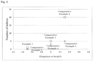
- Fig. 3 is a graph showing a relationship between the elongation at break of the positive electrode substrate and the number of defects in a winding step.
- the average thickness of the positive active material layer was more than 35 ⁇ m, the peel strength (180° peel strength between the positive active material layer and the positive electrode substrate) was also less than 0.6 N/mm, and the positive active material layer was apt to flake.
- the average thickness of the positive active material layer was 35 ⁇ m or less, the peel strength was 0.6 N/mm or more, and the flaking of the positive active material layer could be suppressed.
- the present invention can be applied to a nonaqueous electrolyte energy storage device used as a power source for electronic devices such as personal computers and communication terminals, automobiles, and the like, and a positive electrode and the like provided in the nonaqueous electrolyte energy storage device.
Landscapes
- Chemical & Material Sciences (AREA)
- Engineering & Computer Science (AREA)
- Materials Engineering (AREA)
- Chemical Kinetics & Catalysis (AREA)
- Electrochemistry (AREA)
- General Chemical & Material Sciences (AREA)
- Battery Electrode And Active Subsutance (AREA)
Applications Claiming Priority (2)
| Application Number | Priority Date | Filing Date | Title |
|---|---|---|---|
| JP2022171612 | 2022-10-26 | ||
| PCT/JP2023/036849 WO2024090207A1 (fr) | 2022-10-26 | 2023-10-11 | Électrode positive pour élément de stockage d'énergie électrolytique non aqueux, et élément de stockage d'énergie électrolytique non aqueux |
Publications (2)
| Publication Number | Publication Date |
|---|---|
| EP4579779A1 true EP4579779A1 (fr) | 2025-07-02 |
| EP4579779A4 EP4579779A4 (fr) | 2026-01-14 |
Family
ID=90830771
Family Applications (1)
| Application Number | Title | Priority Date | Filing Date |
|---|---|---|---|
| EP23882416.3A Pending EP4579779A4 (fr) | 2022-10-26 | 2023-10-11 | Électrode positive pour élément de stockage d'énergie électrolytique non aqueux, et élément de stockage d'énergie électrolytique non aqueux |
Country Status (4)
| Country | Link |
|---|---|
| EP (1) | EP4579779A4 (fr) |
| JP (1) | JPWO2024090207A1 (fr) |
| CN (1) | CN119816949A (fr) |
| WO (1) | WO2024090207A1 (fr) |
Family Cites Families (7)
| Publication number | Priority date | Publication date | Assignee | Title |
|---|---|---|---|---|
| JPH09231985A (ja) * | 1996-02-20 | 1997-09-05 | Sony Corp | 非水電解液電池 |
| JP6338104B2 (ja) * | 2014-08-06 | 2018-06-06 | 株式会社豊田自動織機 | リチウムイオン二次電池用正極およびその製造方法ならびにリチウムイオン二次電池およびその製造方法 |
| JP6770701B2 (ja) | 2016-05-02 | 2020-10-21 | 株式会社Gsユアサ | 蓄電素子 |
| CN113299875A (zh) * | 2018-02-26 | 2021-08-24 | 宁德新能源科技有限公司 | 极片和锂离子电池 |
| KR102682128B1 (ko) * | 2018-11-07 | 2024-07-08 | 삼성전자주식회사 | 전고체전지용 무음극 코팅층 및 이를 포함하는 전고체전지 |
| CN111200108B (zh) * | 2018-11-16 | 2021-03-19 | 宁德时代新能源科技股份有限公司 | 一种电池 |
| JP2022085523A (ja) * | 2020-11-27 | 2022-06-08 | トヨタ自動車株式会社 | 全固体電池用負極 |
-
2023
- 2023-10-11 CN CN202380063018.3A patent/CN119816949A/zh active Pending
- 2023-10-11 WO PCT/JP2023/036849 patent/WO2024090207A1/fr not_active Ceased
- 2023-10-11 EP EP23882416.3A patent/EP4579779A4/fr active Pending
- 2023-10-11 JP JP2024552947A patent/JPWO2024090207A1/ja active Pending
Also Published As
| Publication number | Publication date |
|---|---|
| EP4579779A4 (fr) | 2026-01-14 |
| JPWO2024090207A1 (fr) | 2024-05-02 |
| CN119816949A (zh) | 2025-04-11 |
| WO2024090207A1 (fr) | 2024-05-02 |
Similar Documents
| Publication | Publication Date | Title |
|---|---|---|
| EP4325596A1 (fr) | Élément de stockage d'énergie | |
| EP4343910A1 (fr) | Élément de stockage d'énergie | |
| EP4290617A1 (fr) | Élément de stockage d'énergie à électrolyte non aqueux | |
| EP4521504A1 (fr) | Élément de stockage d'énergie | |
| EP4459693A1 (fr) | Élément de stockage d'énergie, et dispositif de stockage d'énergie | |
| US20250015355A1 (en) | Nonaqueous electrolyte energy storage device | |
| EP4336581A1 (fr) | Élément de stockage d?énergie et dispositif de stockage d?énergie | |
| EP4300524A1 (fr) | Élément de stockage d'électricité | |
| EP4280330A1 (fr) | Élément de stockage d'énergie à électrolyte non aqueux | |
| EP4307405A1 (fr) | Élément de stockage d'électricité à électrolyte non aqueux | |
| US12451486B2 (en) | Energy storage device and energy storage apparatus | |
| US20230155180A1 (en) | Energy storage device, method for manufacturing the same and energy storage apparatus | |
| EP4579779A1 (fr) | Électrode positive pour élément de stockage d'énergie électrolytique non aqueux, et élément de stockage d'énergie électrolytique non aqueux | |
| EP4485606A1 (fr) | Élément de stockage d'énergie à électrolyte non aqueux | |
| EP4492499A1 (fr) | Particules de matériau actif, électrode, élément de stockage d'énergie et dispositif de stockage d'énergie | |
| EP4310939A1 (fr) | Élément d'accumulation d'énergie électrique | |
| EP4322258A1 (fr) | Élément de stockage d'énergie à électrolyte non aqueux et dispositif de stockage d'énergie | |
| EP4485605A1 (fr) | Élément de stockage d'énergie à électrolyte non aqueux | |
| EP4632864A1 (fr) | Élément de stockage d'électricité à électrolyte non aqueux | |
| US20250079497A1 (en) | Energy storage device and energy storage apparatus | |
| EP4525115A1 (fr) | Élément de stockage d'énergie | |
| EP4425634A1 (fr) | Élément de stockage d'énergie à électrolyte non aqueux, dispositif et procédé d'utilisation d'un élément de stockage d'énergie à électrolyte non aqueux | |
| EP4664546A1 (fr) | Électrode négative pour élément de stockage d'énergie électrolytique non aqueux, et élément de stockage d'énergie électrolytique non aqueux | |
| EP4539167A1 (fr) | Élément de stockage d'énergie à électrolyte non aqueux | |
| US20250391850A1 (en) | Electrode, energy storage device, and energy storage apparatus |
Legal Events
| Date | Code | Title | Description |
|---|---|---|---|
| STAA | Information on the status of an ep patent application or granted ep patent |
Free format text: STATUS: THE INTERNATIONAL PUBLICATION HAS BEEN MADE |
|
| PUAI | Public reference made under article 153(3) epc to a published international application that has entered the european phase |
Free format text: ORIGINAL CODE: 0009012 |
|
| STAA | Information on the status of an ep patent application or granted ep patent |
Free format text: STATUS: REQUEST FOR EXAMINATION WAS MADE |
|
| 17P | Request for examination filed |
Effective date: 20250324 |
|
| AK | Designated contracting states |
Kind code of ref document: A1 Designated state(s): AL AT BE BG CH CY CZ DE DK EE ES FI FR GB GR HR HU IE IS IT LI LT LU LV MC ME MK MT NL NO PL PT RO RS SE SI SK SM TR |
|
| A4 | Supplementary search report drawn up and despatched |
Effective date: 20251215 |
|
| RIC1 | Information provided on ipc code assigned before grant |
Ipc: H01M 4/13 20100101AFI20251209BHEP Ipc: H01M 4/64 20060101ALI20251209BHEP Ipc: H01M 4/66 20060101ALI20251209BHEP Ipc: H01M 4/02 20060101ALN20251209BHEP |
|
| DAV | Request for validation of the european patent (deleted) | ||
| DAX | Request for extension of the european patent (deleted) |