EP4579862A1 - Élément de batterie, batterie et dispositif électronique - Google Patents
Élément de batterie, batterie et dispositif électronique Download PDFInfo
- Publication number
- EP4579862A1 EP4579862A1 EP22969690.1A EP22969690A EP4579862A1 EP 4579862 A1 EP4579862 A1 EP 4579862A1 EP 22969690 A EP22969690 A EP 22969690A EP 4579862 A1 EP4579862 A1 EP 4579862A1
- Authority
- EP
- European Patent Office
- Prior art keywords
- insulation layer
- porous insulation
- electrode plate
- battery cell
- separator
- Prior art date
- Legal status (The legal status is an assumption and is not a legal conclusion. Google has not performed a legal analysis and makes no representation as to the accuracy of the status listed.)
- Pending
Links
Images




Classifications
-
- H—ELECTRICITY
- H01—ELECTRIC ELEMENTS
- H01M—PROCESSES OR MEANS, e.g. BATTERIES, FOR THE DIRECT CONVERSION OF CHEMICAL ENERGY INTO ELECTRICAL ENERGY
- H01M10/00—Secondary cells; Manufacture thereof
- H01M10/05—Accumulators with non-aqueous electrolyte
- H01M10/058—Construction or manufacture
- H01M10/0587—Construction or manufacture of accumulators having only wound construction elements, i.e. wound positive electrodes, wound negative electrodes and wound separators
-
- H—ELECTRICITY
- H01—ELECTRIC ELEMENTS
- H01M—PROCESSES OR MEANS, e.g. BATTERIES, FOR THE DIRECT CONVERSION OF CHEMICAL ENERGY INTO ELECTRICAL ENERGY
- H01M10/00—Secondary cells; Manufacture thereof
- H01M10/04—Construction or manufacture in general
- H01M10/0431—Cells with wound or folded electrodes
-
- H—ELECTRICITY
- H01—ELECTRIC ELEMENTS
- H01M—PROCESSES OR MEANS, e.g. BATTERIES, FOR THE DIRECT CONVERSION OF CHEMICAL ENERGY INTO ELECTRICAL ENERGY
- H01M10/00—Secondary cells; Manufacture thereof
- H01M10/05—Accumulators with non-aqueous electrolyte
- H01M10/058—Construction or manufacture
- H01M10/0583—Construction or manufacture of accumulators with folded construction elements except wound ones, i.e. folded positive or negative electrodes or separators, e.g. with "Z"-shaped electrodes or separators
-
- H—ELECTRICITY
- H01—ELECTRIC ELEMENTS
- H01M—PROCESSES OR MEANS, e.g. BATTERIES, FOR THE DIRECT CONVERSION OF CHEMICAL ENERGY INTO ELECTRICAL ENERGY
- H01M50/00—Constructional details or processes of manufacture of the non-active parts of electrochemical cells other than fuel cells, e.g. hybrid cells
- H01M50/40—Separators; Membranes; Diaphragms; Spacing elements inside cells
- H01M50/409—Separators, membranes or diaphragms characterised by the material
- H01M50/411—Organic material
- H01M50/414—Synthetic resins, e.g. thermoplastics or thermosetting resins
- H01M50/417—Polyolefins
-
- H—ELECTRICITY
- H01—ELECTRIC ELEMENTS
- H01M—PROCESSES OR MEANS, e.g. BATTERIES, FOR THE DIRECT CONVERSION OF CHEMICAL ENERGY INTO ELECTRICAL ENERGY
- H01M50/00—Constructional details or processes of manufacture of the non-active parts of electrochemical cells other than fuel cells, e.g. hybrid cells
- H01M50/40—Separators; Membranes; Diaphragms; Spacing elements inside cells
- H01M50/46—Separators, membranes or diaphragms characterised by their combination with electrodes
-
- H—ELECTRICITY
- H01—ELECTRIC ELEMENTS
- H01M—PROCESSES OR MEANS, e.g. BATTERIES, FOR THE DIRECT CONVERSION OF CHEMICAL ENERGY INTO ELECTRICAL ENERGY
- H01M50/00—Constructional details or processes of manufacture of the non-active parts of electrochemical cells other than fuel cells, e.g. hybrid cells
- H01M50/40—Separators; Membranes; Diaphragms; Spacing elements inside cells
- H01M50/463—Separators, membranes or diaphragms characterised by their shape
- H01M50/466—U-shaped, bag-shaped or folded
-
- H—ELECTRICITY
- H01—ELECTRIC ELEMENTS
- H01M—PROCESSES OR MEANS, e.g. BATTERIES, FOR THE DIRECT CONVERSION OF CHEMICAL ENERGY INTO ELECTRICAL ENERGY
- H01M50/00—Constructional details or processes of manufacture of the non-active parts of electrochemical cells other than fuel cells, e.g. hybrid cells
- H01M50/40—Separators; Membranes; Diaphragms; Spacing elements inside cells
- H01M50/489—Separators, membranes, diaphragms or spacing elements inside the cells, characterised by their physical properties, e.g. swelling degree, hydrophilicity or shut down properties
-
- H—ELECTRICITY
- H01—ELECTRIC ELEMENTS
- H01M—PROCESSES OR MEANS, e.g. BATTERIES, FOR THE DIRECT CONVERSION OF CHEMICAL ENERGY INTO ELECTRICAL ENERGY
- H01M50/00—Constructional details or processes of manufacture of the non-active parts of electrochemical cells other than fuel cells, e.g. hybrid cells
- H01M50/40—Separators; Membranes; Diaphragms; Spacing elements inside cells
- H01M50/489—Separators, membranes, diaphragms or spacing elements inside the cells, characterised by their physical properties, e.g. swelling degree, hydrophilicity or shut down properties
- H01M50/491—Porosity
-
- H—ELECTRICITY
- H01—ELECTRIC ELEMENTS
- H01M—PROCESSES OR MEANS, e.g. BATTERIES, FOR THE DIRECT CONVERSION OF CHEMICAL ENERGY INTO ELECTRICAL ENERGY
- H01M50/00—Constructional details or processes of manufacture of the non-active parts of electrochemical cells other than fuel cells, e.g. hybrid cells
- H01M50/40—Separators; Membranes; Diaphragms; Spacing elements inside cells
- H01M50/489—Separators, membranes, diaphragms or spacing elements inside the cells, characterised by their physical properties, e.g. swelling degree, hydrophilicity or shut down properties
- H01M50/494—Tensile strength
-
- Y—GENERAL TAGGING OF NEW TECHNOLOGICAL DEVELOPMENTS; GENERAL TAGGING OF CROSS-SECTIONAL TECHNOLOGIES SPANNING OVER SEVERAL SECTIONS OF THE IPC; TECHNICAL SUBJECTS COVERED BY FORMER USPC CROSS-REFERENCE ART COLLECTIONS [XRACs] AND DIGESTS
- Y02—TECHNOLOGIES OR APPLICATIONS FOR MITIGATION OR ADAPTATION AGAINST CLIMATE CHANGE
- Y02E—REDUCTION OF GREENHOUSE GAS [GHG] EMISSIONS, RELATED TO ENERGY GENERATION, TRANSMISSION OR DISTRIBUTION
- Y02E60/00—Enabling technologies; Technologies with a potential or indirect contribution to GHG emissions mitigation
- Y02E60/10—Energy storage using batteries
Definitions
- This application relates to the field of battery technologies, and specifically to a battery cell, a battery, and an electric apparatus.
- At least one electrode assembly is typically provided in a battery cell.
- the electrode assembly may be processed into a roll-shaped structure by winding a positive electrode plate, a negative electrode plate, and a separator that separates the positive electrode plate from the negative electrode plate.
- the electrode assembly has a body region and bent regions disposed at ends of the body region.
- metal precipitation is likely to occur in the bent region of the electrode assembly, and as time goes on, dendrites are easily grown in the bent region. Dendrites are prone to causing internal short circuits in the battery cell, affecting the safety of the battery cell.
- Embodiments of this application provide a battery cell, a battery, and an electric apparatus to solve the problem that dendrites are easily grown in a bent region of an electrode assembly of an existing battery cell, causing internal short circuits in the battery cell and affecting the safety of the battery cell.
- a battery cell includes at least one electrode assembly, and the electrode assembly includes a positive electrode plate, a negative electrode plate, a separator, and a porous insulation layer, where
- the porous insulation layer is disposed between the bent portion of the positive electrode plate or the negative electrode plate at any circle and the separator. Based on this, the pores of the porous insulation layer can allow active ions to penetrate freely, so as to ensure that the porous insulation layer does not have great impact on the charging and discharging process of the battery cell, thereby ensuring the charging and discharging performance of the battery cell. On this basis, the porous insulation layer with insulation properties can also hinder the formation of dendrites.
- the porous insulation layer disposed between the bent portion of the electro de plate and the separator can further buffer the bending stress borne by the bent part of the electrode plate.
- This can effectively reduce the risk of a decrease in the active material caused by tearing of the bent part of the electrode plate, and effectively reduce the risk of aggravation of metal precipitation at the bent region of the electrode assembly caused by the decrease in the active material, effectively lowering the growth speed of dendrites, thereby correspondingly prolonging the service life of the battery cell, and correspondingly improving the safety of the battery cell.
- At least one porous insulation layer is disposed on an inner side of the positive electrode plate at an innermost circle.
- the porous insulation layer disposed on the inner side of the bent part of the positive electrode plate at the innermost circle can be used to insulate and block growing dendrites so as to prevent the dendrites from coming into direct contact with and conducting electricity to the positive electrode plate and the negative electrode plate.
- the porous insulation layer disposed on the inner side of the bent part of the positive electrode plate at the innermost circle can be used to buffer the squeezing stress borne by the bent part of the positive electrode plate at the innermost circle, so as to reduce the risk of tearing of the bent part of the positive electrode plate at the innermost circle leading to a decrease in the active material; and even can buffer the tensile stress borne by the bent part of the negative electrode plate at the innermost circle, so as to reduce the risk of tearing of the bent part of the negative electrode plate at the innermost circle leading to a decrease in the active material.
- the risk of aggravation of metal precipitation caused by the decrease in the active material can be effectively reduced, and the growth speed of dendrites between the positive electrode plate at the innermost circle and the negative electrode plate at the innermost circle can be effectively reduced, correspondingly prolonging the service life of the battery cell, and correspondingly improving the safety of the battery cell.
- At least one porous insulation layer is disposed on an outer side of the positive electrode plate at an innermost circle.
- the porous insulation layer disposed on the outer side of the bent part of the positive electrode plate at the innermost circle can be used to buffer the tensile stress borne by the bent part of the positive electrode plate at the innermost circle, so as to reduce the risk of tearing of the bent part of the positive electrode plate at the innermost circle leading to a decrease in the active material; and even can buffer the squeezing stress borne by the bent part of the negative electrode plate at the second innermost circle, so as to reduce the risk of tearing of the bent part of the negative electrode plate at the second innermost circle leading to a decrease in the active material.
- the risk of aggravation of metal precipitation caused by the decrease in the active material can be effectively reduced, and the growth speed of dendrites between the positive electrode plate at the innermost circle and the negative electrode plate at the second innermost circle can be effectively reduced, correspondingly prolonging the service life of the battery cell, and correspondingly improving the safety of the battery cell.
- the porous insulation layer disposed on the outer side of the bent part of the positive electrode plate at the innermost circle can be used to insulate and block dendrites growing towards the porous insulation layer so as to prevent the dendrites from coming into direct contact with and conducting electricity to the positive electrode plate at the innermost circle and the negative electrode plate at the second innermost circle.
- two porous insulation layers are provided in the bent region, one of the porous insulation layers is disposed on an inner side of the positive electrode plate at an innermost circle, and the other of the porous insulation layers is disposed on an outer side of the positive electrode plate at an innermost circle.
- the bent region can effectively delay the risk of short circuits between "the positive electrode plate at the innermost circle and the negative electrode plate at the innermost circle” and “the positive electrode plate at the innermost circle and the negative electrode plate at the second innermost circle” which are prone to metal precipitation and have relatively serious metal precipitation, and effectively alleviate the squeezing stress and tensile stress at the bent part of the positive electrode plate at the innermost circle that bears relatively great bending stress and is prone to tearing defects, so as to reduce the risk of bending tearing, thereby effectively prolonging the service life of the battery cell, and effectively improving the safety of the battery cell.
- the number of the porous insulation layers can also be reduced while the function of the porous insulation layer is maximized, thereby ensuring and increasing the energy density of the electrode assembly and the battery cell.
- the electrode assembly has a body region and bent regions disposed at ends of the body region; and the porous insulation layer has a curved section curvedly disposed in the bent region, and an extension section connected to an end of the curved section and disposed in the body region.
- the area for disposing the porous insulation layer can be correspondingly extended, and the porous insulation layer has a relatively wide tolerance range in terms of its preset position on the continuous positive electrode plate or the continuous negative electrode plate.
- the porous insulation layer can have the curved section clamped between the bent part of the electrode plate and the separator, and the extension section that can be adaptively extended to the body region according to the position tolerance, thereby effectively reducing the precision requirement for the preset position of the porous insulation layer on the continuous positive electrode plate or the continuous negative electrode plate, and effectively ensuring and improving the production yield rate of the electrode assembly.
- the relative position and relative state of the porous insulation layer can further be reliably and stably maintained through the curved section clamped between the bent part of the electrode plate and the separator and the extension section clamped between the flat portion of the electrode plate and the separator, thereby effectively reducing the displacement risk of the porous insulation layer during the use of the battery cell, and effectively ensuring that the porous insulation layer can permanently, stably, and reliably function during the use of the battery cell.
- the porous insulation layer is adhered to the positive electrode plate or the negative electrode plate through a dissolvable adhesive.
- the porous insulation layer before winding, can be adhered to a preset position of the continuous positive electrode plate or the continuous negative electrode plate through a dissolvable adhesive, so as to maintain the preset position and preset state with respect to the electrode plate.
- a dissolvable adhesive so as to maintain the preset position and preset state with respect to the electrode plate.
- the porous insulation layer can be wound with the continuous positive electrode plate or the continuous negative electrode plate to the bent region, with a stable position and state with respect to the electrode plate.
- This can allow for convenient and quick installation of the porous insulation layer, effectively ensure and improve the position accuracy and utility of the porous insulation layer in the formed electrode assembly, and effectively ensure and improve the production efficiency and production yield rate of the electrode assembly.
- the battery cell includes an electrolyte for infiltrating the electrode assembly, and the electrolyte contains the dissolvable adhesive.
- the dissolvable adhesive is a modified acrylic pressure-sensitive adhesive
- the electrolyte contains modified acrylic resin
- an absolute value of a difference between porosity of the porous insulation layer and porosity of the separator is less than or equal to 25%.
- the porosity of the porous insulation layer can be made not much different from the porosity of the separator. This helps active ions to freely and normally penetrate the porous insulation layer and the separator, thereby effectively ensuring that the disposition of the porous insulation layer does not cause great impact on the charging and discharging process of the battery cell, and effectively ensuring the charging and discharging performance of the battery cell.
- an absolute value of a difference between porosity of the porous insulation layer and porosity of the separator is less than or equal to 10%.
- the porosity of the porous insulation layer can be made close to the porosity of the separator. This helps active ions to freely and normally penetrate the porous insulation layer and the separator, thereby effectively ensuring that the disposition of the porous insulation layer does not cause great impact on the charging and discharging process of the battery cell, and effectively ensuring and improving the charging and discharging performance of the battery cell.
- the porous insulation layer is a polyolefin separator.
- the porous insulation layer can be made by using the polyolefin separator such as a polypropylene separator, so as to ensure that the porosity of the porous insulation layer is similar to or even the same as the porosity of the separator.
- This can ensure that the active ions can freely and normally penetrate the porous insulation layer and the separator, thereby effectively ensuring that the disposition of the porous insulation layer does not cause great impact on the charging and discharging process of the battery cell, and effectively ensuring the charging and discharging performance of the battery cell.
- the active ions intercalated in the negative electrode active material of the negative electrode plate are released, and the active ions released from the negative electrode plate can penetrate the pores of the separator to move to the positive electrode plate and be intercalated into a positive electrode active material of the positive electrode plate.
- the second portion 202 may be a hollow structure with one end open, and the first portion 201 may be a plate structure, where the first portion 201 covers the open side of the second portion 202 for the first portion 201 and the second portion 202 to jointly define an accommodating space.
- the first portion 201 and the second portion 202 may both be hollow structures with one side open, where the open side of the first portion 201 is engaged with the open side of the second portion 202.
- the box 200 formed by the first portion 201 and the second portion 202 may have a variety of shapes, for example, cylinder or cuboid.
- the battery units 100 are provided in plurality, and the plurality of battery units 100 may be connected in series, parallel, or series-parallel, where being connected in series-parallel means a combination of series and parallel connections of the plurality of battery units 100.
- the battery unit 100 may be a battery cell.
- the plurality of battery cells may be directly connected in series, parallel, or series-parallel, and then an entirety of the plurality of battery cells is accommodated in the box 200.
- the battery cell may be a lithium-ion secondary battery, a lithium-ion primary battery, a lithium-sulfur battery, a sodium-lithium ion battery, a sodium-ion battery, or a magnesium-ion battery, or the like.
- the battery cell may be in a shape of a cylinder, a flat body, a cuboid, or other shapes.
- the battery cell may be packaged in different manners to form a cylindrical battery cell, a prismatic battery cell, a pouch battery cell, or the like. None of these is limited in this application.
- the battery unit 100 may be a battery module or a battery group.
- a plurality of battery cells can be first connected in series, parallel or series-parallel to form a modular structure, namely a battery module or a battery group; and then a plurality of battery modules or battery groups are connected in series, parallel or series-parallel to form an entirety which is accommodated in the box 200.
- the battery 1 may not include the box 200. Instead, a plurality of battery cells are electrically connected, and are made into an entirety through a necessary fixing structure, and then the entirety is placed into an electric apparatus.
- FIGs. 3 and 4 are schematic structural diagrams of battery cells according to some embodiments of this application.
- a battery cell is the smallest unit for storing and outputting electrical energy.
- the battery cell includes components such as an electrode assembly 10, an electrolyte 20, a housing 30, and an end cover 40.
- the end cover 40 refers to a component that covers an opening of the housing 30 to isolate an internal environment of the battery cell from an external environment thereof.
- a shape of the end cover 40 may be adapted to a shape of the housing 30 to fit the housing 30.
- the end cover 40 may be made of a material with given hardness and strength, so that the end cover 40 is less likely to deform when subjected to squeezing and collision, allowing the battery cell to have higher structural strength and enhanced safety performance.
- this embodiment does not limit the material of the end cover 40 to a sole type, and the end cover 40 may be made of materials such as copper, iron, aluminum, stainless steel, aluminum alloy, or plastic.
- an electrode terminal 50 may be provided on the end cover 40.
- the electrode terminal 50 may be configured to be electrically connected to the electrode assembly 10 for outputting or inputting electrical energy.
- the end cover 40 may further be provided with a pressure relief mechanism (not shown in the figure) configured to relieve internal pressure when the internal pressure or temperature in the battery cell reaches a threshold.
- an insulator (not shown in the figure) may further be provided on an inner side of the end cover 40. The insulator may be configured to isolate an electrically connected component in the housing 30 from the end cover 40 to reduce a risk of short circuits.
- the insulator may be made of plastic, rubber, or the like.
- the housing 30 is a component configured to form the internal environment of the battery cell together with the end cover 40.
- the internal environment formed by the housing 30 and the end cover 40 can be used to accommodate components such as the electrode assembly 10 and the electrolyte 20.
- the housing 30 and the end cover 40 may be independent components, an opening may be provided in the housing 30, and the end cover 40 covers the opening to form the internal environment of the battery cell.
- the end cover 40 and the housing 30 may also be integrated. Specifically, the end cover 40 and the housing 30 may form a shared connection surface before other components are disposed inside the housing, and then the housing 30 is covered with the end cover 40 when inside of the housing 30 needs to be enclosed.
- the housing 30 may be of various shapes and sizes, such as a cuboid, a cylinder, and a hexagonal prism. Specifically, a shape of the housing 30 may be determined according to a specific shape and size of the electrode assembly 10.
- the housing 30 may be made of various materials, such as copper, iron, aluminum, stainless steel, aluminum alloy, and plastic, and is not limited to a sole type in the embo diments of this application.
- the electrode assembly 10 is a component in which electrochemical reactions occur in the battery cell.
- the housing 30 may include one or more electrode assemblies 10. Refer to FIG. 5 .
- the electrode assembly 10 includes a positive electrode plate 11, a negative electrode plate 12, and a separator 13.
- the separator 13 separates the positive electrode plate 11 from the negative electrode plate 12.
- the positive electrode plate 11, the negative electrode plate 12, and the separator 13 that separates the positive electrode plate 11 from the negative electrode plate 12 may be processed into a roll-shaped structure in a winding method.
- the electrode assembly 10 of a roll-shaped structure has a body region 15 and bent regions 16 disposed at ends of the body region 15. A part of the positive electrode plate 11 and a part of the negative electrode plate 12 that do not have an active material form tabs respectively.
- the tab is a current transmission terminal of the electrode assembly 10, and is used to connect to an electrode terminal 50 to transmit current.
- the tab of the positive electrode plate 11 is a positive electrode tab 111
- the tab of the negative electrode plate 12 is a negative electrode tab 121.
- the positive electrode tab 111 and the negative electrode tab 121 may be located on the same side of the body region 15 or opposite sides of the body region 15, respectively.
- the electrolyte 20 is a liquid that infiltrates the electrode assembly 10.
- the positive electrode plate 11 When the battery cell is being charged, the positive electrode plate 11 generates active ions, and the active ions provided by the positive electrode plate 11 can penetrate the pores of the separator 13 to move to the negative electrode plate 12 through the electrolyte 20 and be intercalated into the negative electrode active material of the negative electrode plate 12.
- the active ions intercalated into the negative electrode active material of the negative electrode plate 12 are released, and the active ions released from the negative electrode plate 12 can penetrate the pores of the separator 13 to move to the positive electrode plate 11 through the electrolyte 20 and be intercalated into the positive electrode active material of the positive electrode plate 11.
- the battery cell includes at least one electrode assembly 10.
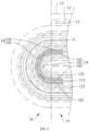
- the electrode assembly 10 includes a positive electrode plate 11, a negative electrode plate 12, a separator 13, and a porous insulation layer 14.
- the positive electrode plate 11, the separator 13, and the negative electrode plate 12 are stacked and wound.
- At least a portion of the porous insulation layer 14 is disposed in a bent region 16 of the electrode assembly 10, and the porous insulation layer 14 is disposed between the positive electrode plate 11 and the separator 13 or disposed between the negative electrode plate 12 and the separator 13.
- the electrode assembly 10 is a component in which electrochemical reactions occur in the battery cell.
- One or more electrode assemblies 10 can be provided inside the battery cell.
- the positive electrode plate 11 is a continuous positive electrode plate 11
- the negative electrode plate 12 is a continuous negative electrode plate 12
- the separator 13 is a continuous separator 13.
- Two continuous separators 13 are provided. Before winding, one of the continuous separators 13 is provided between the continuous positive electrode plate 11 and the continuous negative electrode plate 12, and the other continuous separator 13 is provided on a side of the continuous negative electrode plate 12 facing away from the continuous positive electrode plate 11, or provided on a side of the continuous positive electrode plate 11 facing away from the continuous negative electrode plate 12.
- the two continuous separators 13 can separate the positive electrode plate 11 from the negative electrode plate 12 to prevent the positive electrode plate 11 and the negative electrode plate 12 from coming into direct contact, while such contact causes a short circuit.
- the separator 13 has a plurality of pores to allow active ions to pass through freely.
- the porous insulation layer 14 may be disposed in one bent region 16, or the porous insulation layers 14 may be disposed in multiple bent regions 16.
- porous insulation layer 14 may be provided in the bent region 16 provided with the porous insulation layer 14.
- the porous insulation layer 14 may be disposed between the positive electrode plate 11 at any circle and the separator 13 or disposed between the negative electrode plate 12 at any circle and the separator 13.
- the porous insulation layer 14 may be pre-disposed at a preset position of the continuous positive electrode plate 11 or the continuous negative electrode plate 12 before winding, so that when the positive electrode plate 11, the separator 13, and the negative electrode plate 12 are wound into a roll-shaped structure, the porous insulation layer 14 can be clamped between the bent part of the electrode plate and the separator 13. This can allow for convenient and quick installation of the porous insulation layer 14.
- the bent part of the electrode plate and the separator 13 can be used together to tightly clamp the porous insulation layer 14, thereby keeping the position and state of the porous insulation layer 14 stable.
- the porous insulation layer 14 has a plurality of pores to allow active ions to pass through freely. Therefore, during the charging and discharging of the battery cell, active ions can freely penetrate the porous insulation layer 14 and the separator 13 to migrate between the positive electrode plate 11 and the negative electrode plate 12. This can effectively ensure that the disposition of the porous insulation layer 14 does not cause great impact on the charging and discharging process of the battery cell, thereby effectively ensuring the charging and discharging performance of the battery cell.
- the porous insulation layer 14 is made of an insulation material, so the porous insulation layer 14 has relatively good insulation properties.
- the porous insulation layer 14 when the porous insulation layer 14 is provided between the bent part of the positive electrode plate 11 at any circle and the separator 13, even if active ions are released from the bent part of the negative electrode plate 12 during the charging of the battery cell, and dendrites grow from a defective part of the bent part of the separator 13 as the time of using the battery cell increases, the porous insulation layer 14 provided between the positive electrode plate 11 at any circle and the separator 13 can insulate and block the grown dendrites. This prevents the dendrites from coming into direct contact with and conducting electricity to the positive electrode plate 11 and the negative electrode plate 12, and can even effectively delay the growth speed of the dendrites to some extent.
- the porous insulation layer 14 When the porous insulation layer 14 is provided between the bent part of the negative electrode plate 12 at any circle and the separator 13, even when active ions are released from the bent part of the negative electrode plate 12 during the charging of the battery cell, the porous insulation layer 14 provided between the bent part of the negative electrode plate 12 at any circle and the separator 13 can shield and protect the bent part of the separator 13.
- the porous insulation layer 14 is disposed between the bent portion of the positive electrode plate 11 or the negative electrode plate 12 at any circle and the separator 13. Based on this, the pores of the porous insulation layer 14 can allow active ions to penetrate freely, so as to ensure that the porous insulation layer 14 does not have great impact on the charging and discharging process of the battery cell, thereby ensuring the charging and discharging performance of the battery cell. On this basis, the porous insulation layer 14 with insulation properties can also hinder the formation of dendrites.
- At least one porous insulation layer 14 is disposed on an outer side of the positive electrode plate 112 at an innermost circle.
- the porous insulation layer 14 disposed on the outer side of the bent part of the positive electrode plate 112 at the innermost circle can be used to buffer the tensile stress borne by the bent part of the positive electrode plate 112 at the innermost circle, so as to reduce the risk of tearing of the bent part of the positive electrode plate 112 at the innermost circle leading to a decrease in the active material; and even can buffer the squeezing stress borne by the bent part of the negative electrode plate 123 at the second innermost circle, so as to reduce the risk of tearing of the bent part of the negative electrode plate 123 at the second innermost circle leading to a decrease in the active material.
- the negative electrode plate 123 at the second innermost circle is a negative electrode plate 12 located on the outer side of the positive electrode plate 112 at the innermost circle.
- the active ions provided by the outer surface of the positive electrode plate 112 at the innermost circle can freely pass through the porous insulation layer 14 and the separator 13 to move to the negative electrode plate 123 at the second innermost circle and be intercalated into the negative electrode active material of the negative electrode plate 123 at the second innermost circle.
- the porous insulation layer 14 disposed on the outer side of the bent part of the positive electrode plate 112 at the innermost circle can be used to insulate and block dendrites growing towards the porous insulation layer 14 so as to prevent the dendrites from coming into direct contact with and conducting electricity to the positive electrode plate 112 at the innermost circle and the negative electrode plate 123 at the second innermost circle.
- the bent region 16 is provided with two porous insulation layers 14, one of the porous insulation layers 14 is disposed on an inner side of the positive electrode plate 112 at an innermost circle, and the other of the porous insulation layers 14 is disposed on an outer side of the positive electrode plate 112 at the innermost circle.
- the porous insulation layer 14 may be disposed in one bent region 16, or the porous insulation layers 14 may be disposed in multiple bent regions 16. In the bent region 16 provided with the porous insulation layer 14, one porous insulation layer 14 is disposed on each of the inner side and the outer side of the bent part of the positive electrode plate 112 at the innermost circle.
- the bent region 16 can effectively delay the risk of short circuits "between the positive electrode plate 112 at the innermost circle and the negative electrode plate 122 at the innermost circle” and "between the positive electrode plate 112 at the innermost circle and the negative electrode plate 123 at the second innermost circle” which are prone to metal precipitation and have relatively serious metal precipitation, and effectively alleviate the squeezing stress and tensile stress at the bent part of the positive electrode plate 112 at the innermost circle that bears relatively great bending stress and is prone to tearing defects, so as to reduce the risk of bending tearing, thereby effectively prolonging the service life of the battery cell, and effectively improving the safety of the battery cell.
- the number of the porous insulation layers 14 can also be reduced while the function of the porous insulation layer 14 is maximized, thereby ensuring and increasing the energy density of the electrode assembly 10 and the battery cell.
- the electrode assembly 10 has a body region 15 and bent regions 16 disposed at ends of the body region 15.
- the porous insulation layer 14 has a curved section 141 curvedly disposed in the bent region 16, and an extension section 142 connected to an end portion of the curved section 141 and disposed in the body region 15.
- the electrode assembly 10 of a roll-shaped structure has the body region 15 and the bent regions 16.
- the body region 15 is a relatively flat part located in the relative middle of the roll-shaped structure
- the bent region 16 is a bent part of the roll-shaped structure located at an end of the body region 15.
- the porous insulation layer 14 is pre-disposed at a preset position of the continuous positive electrode plate 11 or the continuous negative electrode plate 12 before winding, in the above solution, the area for disposing the porous insulation layer 14 can be correspondingly extended, and the porous insulation layer 14 has a relatively wide tolerance range in terms of its preset position on the continuous positive electrode plate 11 or the continuous negative electrode plate 12.
- the relative position and relative state of the porous insulation layer 14 can further be reliably maintained through the curved section 141 clamped between the bent part of the electrode plate and the separator 13 and the extension section 142 clamped between the flat portion (that is, part of the electrode plate corresponding to the body region 15) of the electrode plate and the separator 13, thereby effectively reducing the displacement risk of the porous insulation layer 14 during the use of the battery cell, and effectively ensuring that the porous insulation layer 14 can permanently, stably, and reliably function during the use of the battery cell.
- the porous insulation layer 14 is adhered to the positive electrode plate 11 or the negative electrode plate 12 through a dissolvable adhesive 17.
- the dissolvable adhesive 17 is disposed on one side of the porous insulation layer 14 along the thickness direction a thereof.
- the dissolvable adhesive 17 may be applied on the entire region of the side of the porous insulation layer 14, that is, in the thickness direction a of the porous insulation layer 14, a projected area of the dissolvable adhesive 17 is equal to a projected area of the porous insulation layer 14.
- dissolvable adhesive 17 is easily dissolved in the electrolyte 20.
- the porous insulation layer 14 can be adhered to a preset position of the continuous positive electrode plate 11 or the continuous negative electrode plate 12 through a dissolvable adhesive 17, so as to maintain the preset position and preset state with respect to the electrode plate, and wind the porous insulation layer 14, the positive electrode plate 11, the separator 13, and the negative electrode plate 12 into the electrode assembly 10.
- the dissolvable adhesive 17 adhered between the electrode plate and the porous insulation layer 14 can be completely dissolved in the electrolyte 20, or can be partially dissolved in the electrolyte 20 and partially remain between the electrode plate and the porous insulation layer 14.
- the dissolvable adhesive 17 slightly blocks corresponding regions of the electrode plate and the porous insulation layer 14, no great impact is caused on the charging and discharging process of the battery cell. Therefore, the embodiments do not exclude the case that "the dissolvable adhesive 17 is partially dissolved in the electrolyte 20 and partially remains between the electrode plate and the porous insulation layer 14".
- the dissolvable adhesive 17 is a modified acrylic pressure-sensitive adhesive
- the electrolyte 20 contains modified acrylic resin
- the dissolvable adhesive 17 is made of a modified acrylic pressure-sensitive adhesive.
- the modified acrylic pressure-sensitive adhesive has the viscous liquid properties of the pressure-sensitive adhesive, and therefore, in the early stage, can be conveniently, quickly, and reliably applied on one side of the porous insulation layer 14 along the thickness direction a thereof, thereby helping to make an adhesive layer out of the dissolvable adhesive 17.
- the modified acrylic pressure-sensitive adhesive also has the easily degradable characteristics of the modified acrylic resin.
- the electrode assembly 10 and the electrolyte 20 are packed into the interior of the battery cell, it can be quickly dissolved in the electrolyte 20 with barely no any residual adhesive left. Since the modified acrylic pressure-sensitive adhesive is dissolved in the electrolyte 20, the electrolyte 20 inside the battery cell contains the component of modified acrylic resin.
- initial thickness of the dissolvable adhesive 17 is 2 ⁇ m to 8 ⁇ m.
- pore sizes of the pores of the porous insulation layer 14 are A, and thickness of the porous insulation layer 14 is B, where 24 ⁇ B/A ⁇ 400.
- each pore of the porous insulation layer 14 may be circular or other shapes such as rectangular.
- the pore size A of the pore refers to the diameter of the pore.
- the pore size A of the pore refers to the size of the pore in the radial direction perpendicular to the central axis.
- the thickness B of the porous insulation layer 14 refers to the size of the porous insulation layer 14 in its thickness direction a.
- the thickness B of the porous insulation layer 14 is too large, and the pore sizes A of the pores of the porous insulation layer 14 are too small. In this case, a migration path of active ions in the porous insulation layer 14 is too long. In addition, because the pore sizes A of the pores of the porous insulation layer 14 are too small, it is difficult for active ions to migrate, and it is easy to cause more active ions to precipitate.
- the thickness B of the porous insulation layer 14 and the pore sizes A of the pores of the porous insulation layer 14 can be both moderate. This ensures that the dendrites are not prone to pierce or pass through the porous insulation layer 14, thereby ensuring the blocking effect of the porous insulation layer 14 on the dendrites. In addition, this ensures that active ions are easy to migrate in the porous insulation layer 14 and the migration path is relatively short, thereby reducing the risk of precipitation caused by the difficulty in active ion migration. Thus, the service life of the battery cell can be effectively prolonged, and the safety of the battery cell can be effectively improved.
- thickness B of the porous insulation layer 14 is 12 ⁇ m to 20 ⁇ m.
- the thickness B of the porous insulation layer 14 can be ensured to be moderate, so as to reduce the impact of the porous insulation layer 14 on the energy density of the battery cell and the penetration rate of active ions penetrating the porous insulation layer 14 while the relatively good insulating and blocking effect of the porous insulation layer 14 on the dendrites growing towards the porous insulation layer 14 can be ensured.
- the conductivity can be ensured, the charging and discharging performance of the battery cell can be ensured, the service life of the battery cell can be correspondingly prolonged, and the safety of the battery cell can be correspondingly improved.
- the pore sizes A of the pores of the porous insulation layer 14 are 0.05 ⁇ m to 0.5 ⁇ m.
- a larger pore size A of the porous insulation layer 14 means higher air permeability.
- the pore sizes A of the pores of the porous insulation layer 14 increases, when the same amount of the dissolvable adhesive 17 is applied on a side surface of the porous insulation layer 14, the amount of adhesive penetrating into the pores of the porous insulation layer 14 increases, and the amount of adhesive remaining on the surface of the porous insulation layer 14 decreases.
- the adhesion force of the dissolvable adhesive 17 decreases, thus the effect of fixing the porous insulation layer 14 to the electrode plate deteriorates, and thus the penetration rate and conductivity of the active ions deteriorate.
- the electrode assembly 10 and the electrolyte 20 are packed into the interior of the battery cell, as the pore sizes A of the pores of the porous insulation layer 14 increases, the amount of the dissolvable adhesive 17 remaining in the pores of the porous insulation layer 14 increases, resulting in the deterioration of the air permeability and the penetration rate of active ions of the porous insulation layer 14, thereby causing the deterioration of the conductivity.
- the pore sizes A of the pores of the porous insulation layer 14 increase, during the use of the battery cell, the blocking effect of the porous insulation layer 14 on dendrites growing from a defective part of the separator 13 deteriorates, and there may even be a risk of dendrites growing from the pores of the porous insulation layer 14.
- a moderate air permeability of the porous insulation layer 14 can be ensured, thereby ensuring that active ions can freely and normally penetrate the pores of the porous insulation layer 14.
- it can be ensured that a small amount of the adhesive penetrates into the pores of the porous insulation layer 14 when the dissolvable adhesive 17 is applied on a side of the porous insulation layer 14, while a large amount of the adhesive remains on the surface of the porous insulation layer 14. This can ensure the adhesion force of the dissolvable adhesive 17, thereby ensuring that the porous insulation layer 14 can be reliably and temporarily fastened to the electrode plate through the dissolvable adhesive 17.
- tensile strength of the porous insulation layer 14 in the width direction b thereof is greater than or equal to 1000 kgf/cm 2 .
- the length direction a of the porous insulation layer 14 corresponds to the extension direction of the electrode plate, that is, a winding direction of the electrode plate.
- the width direction b of the porous insulation layer 14 corresponds to the width direction of the electrode plate.
- a tensile force is applied to the porous insulation layer 14 along the width direction b until the porous insulation layer 14 cannot withstand the tensile force and breaks, and the tensile strength of the porous insulation layer 14 in the width direction b thereof can be measured.
- the tensile strength of the porous insulation layer 14 in the width direction b thereof can reflect the capability of the porous insulation layer 14 to resist damage in the width direction b thereof when subjected to a tensile force.
- the porous insulation layer 14 Since the porous insulation layer 14 is disposed in the bent region 16, the porous insulation layer 14 is subjected to a tensile force to some extent during both the winding and pre-pressing of the electrode assembly 10 and during the use of the battery cell. Based on this, in the above solution, it can be ensured that the porous insulation layer 14 has sufficient tensile strength in its width direction, and the risk of the porous insulation layer 14 breaking or cracking under the action of tensile force can be effectively reduced.
- this can ensure and improve the insulating and blocking effect of the porous insulation layer 14 on dendrites growing from the defective part of the separator 13, and effectively reduce the risk of the dendrites continuing to grow along a fracture or defective crack of the porous insulation layer 14, thereby correspondingly prolonging the service life of the battery cell, and correspondingly improving the safety of the battery cell.
- the tensile strength of the porous insulation layer 14 in its extension direction can basically also meet the requirements. Therefore, this embodiment does not specifically limit the tensile strength of the porous insulation layer 14 in the extension direction thereof.
- elongation of the porous insulation layer 14 in the width direction b thereof is greater than or equal to 10%.
- a tensile force is applied to the porous insulation layer 14 along the width direction b until the porous insulation layer 14 cannot withstand the tensile force and breaks, a percentage of the tensile deformation portion of the porous insulation layer 14 in the width direction b thereof relative to the original length is the elongation of the porous insulation layer 14 in the width direction b thereof.
- the porous insulation layer 14 disposed in the bent region 16 of the electrode assembly 10 needs to have certain extension deformation performance. Therefore, in the above solution, it can be ensured that the porous insulation layer 14 has a sufficient elongation in its width direction b thereof, so as to ensure that the porous insulation layer 14 can be adaptively elongated and deformed with the electrode assembly 10, thereby ensuring that the effective range of the porous insulation layer 14 can cover the corresponding area of the electrode plate, and ensuring that the porous insulation layer 14 can reliably insulate and block dendrites growing from a defective part of the separator 13.
- shrinkage of the porous insulation layer 14 at 105°C is 0 to 3%.
- the shrinkage of the porous insulation layer 14 at 105°C can be obtained by comparing "the size of the porous insulation layer 14 at 105°C" with "the size of the porous insulation layer 14 at room temperature” to obtain a shrinkage amount.
- the internal temperature of the battery cell gradually increases, causing the porous insulation layer 14 to shrink and deform. If there is too much shrinkage, the effective range of the porous insulation layer 14 may not be able to cover the corresponding area of the entire electrode plate. Based on this, in the above solution, during the use of the battery cell, it can be ensured that the porous insulation layer 14 shrinks with the internal temperature of the battery cell to a relatively small extent, thereby ensuring that the effective range of the porous insulation layer 14 can cover the corresponding area of the electrode plate, and ensuring that the porous insulation layer 14 can reliably insulate and block dendrites growing from a defective part of the separator 13.
- some embodiments of this application further provide a battery 1, where the battery 1 includes the battery cell provided in the embodiments of this application.
- the service life of the battery 1 can be ensured and prolonged, and the use safety of the battery 1 can be ensured and improved.
- the service life of the electric apparatus can be ensured and prolonged, and the use safety of the electric apparatus can be ensured and improved.
Landscapes
- Chemical & Material Sciences (AREA)
- Chemical Kinetics & Catalysis (AREA)
- Electrochemistry (AREA)
- General Chemical & Material Sciences (AREA)
- Engineering & Computer Science (AREA)
- Manufacturing & Machinery (AREA)
- Secondary Cells (AREA)
- Cell Separators (AREA)
Applications Claiming Priority (1)
| Application Number | Priority Date | Filing Date | Title |
|---|---|---|---|
| PCT/CN2022/143462 WO2024138541A1 (fr) | 2022-12-29 | 2022-12-29 | Élément de batterie, batterie et dispositif électronique |
Publications (2)
| Publication Number | Publication Date |
|---|---|
| EP4579862A1 true EP4579862A1 (fr) | 2025-07-02 |
| EP4579862A4 EP4579862A4 (fr) | 2026-01-07 |
Family
ID=91716053
Family Applications (1)
| Application Number | Title | Priority Date | Filing Date |
|---|---|---|---|
| EP22969690.1A Pending EP4579862A4 (fr) | 2022-12-29 | 2022-12-29 | Élément de batterie, batterie et dispositif électronique |
Country Status (4)
| Country | Link |
|---|---|
| US (1) | US20250070266A1 (fr) |
| EP (1) | EP4579862A4 (fr) |
| CN (1) | CN118947003A (fr) |
| WO (1) | WO2024138541A1 (fr) |
Families Citing this family (1)
| Publication number | Priority date | Publication date | Assignee | Title |
|---|---|---|---|---|
| CN119944101B (zh) * | 2025-01-24 | 2026-03-13 | 江苏时代新能源科技有限公司 | 电池单体、电池、用电装置 |
Family Cites Families (8)
| Publication number | Priority date | Publication date | Assignee | Title |
|---|---|---|---|---|
| WO2008143005A1 (fr) * | 2007-05-10 | 2008-11-27 | Hitachi Maxell, Ltd. | Elément électrochimique et son procédé de fabrication |
| KR102883065B1 (ko) * | 2019-01-04 | 2025-11-07 | 셀가드 엘엘씨 | 리튬 전지 또는 커패시터용 폴리이미드 코팅 분리기 |
| CN209389153U (zh) * | 2019-03-20 | 2019-09-13 | 三星(天津)电池有限公司 | 一种卷绕结构的锂离子电池 |
| CN110380136A (zh) * | 2019-08-29 | 2019-10-25 | 东莞塔菲尔新能源科技有限公司 | 一种卷绕电芯、制备工艺以及锂离子电池 |
| WO2021210317A1 (fr) * | 2020-04-13 | 2021-10-21 | 旭化成株式会社 | Séparateur à réticulation chimique empilé de type composite |
| CN212810367U (zh) * | 2020-08-21 | 2021-03-26 | 宁德时代新能源科技股份有限公司 | 电极组件、电池单体、电池和用电装置 |
| CN119208760A (zh) * | 2020-08-21 | 2024-12-27 | 宁德时代新能源科技股份有限公司 | 电极组件、电池单体、电池及制造电极组件的方法和装置 |
| CN217158290U (zh) * | 2022-03-28 | 2022-08-09 | 宁德时代新能源科技股份有限公司 | 电极组件、电池单体、电池及用电装置 |
-
2022
- 2022-12-29 WO PCT/CN2022/143462 patent/WO2024138541A1/fr not_active Ceased
- 2022-12-29 CN CN202280094182.6A patent/CN118947003A/zh active Pending
- 2022-12-29 EP EP22969690.1A patent/EP4579862A4/fr active Pending
-
2024
- 2024-11-11 US US18/943,692 patent/US20250070266A1/en active Pending
Also Published As
| Publication number | Publication date |
|---|---|
| WO2024138541A1 (fr) | 2024-07-04 |
| CN118947003A (zh) | 2024-11-12 |
| US20250070266A1 (en) | 2025-02-27 |
| EP4579862A4 (fr) | 2026-01-07 |
Similar Documents
| Publication | Publication Date | Title |
|---|---|---|
| CN219303740U (zh) | 电池单体、电池及用电装置 | |
| CN219286491U (zh) | 电池单体、电池及用电装置 | |
| EP4131631A1 (fr) | Ensemble électrode, élément de batterie, batterie et appareil consommateur d'énergie | |
| CN117199729B (zh) | 电池单体、电池以及用电装置 | |
| EP4668467A1 (fr) | Élément de batterie, batterie et appareil électrique | |
| CN219575857U (zh) | 电池单体、电池及用电设备 | |
| EP4675730A1 (fr) | Batterie, dispositif électrique et dispositif de stockage d'énergie | |
| JP7594107B2 (ja) | 電極アセンブリ、電池セル、電池及び電力消費装置 | |
| EP4395008A1 (fr) | Module de batterie, batterie et dispositif électrique | |
| JP7761637B2 (ja) | 電極アセンブリ、電池セル、電池、並びに電極アセンブリを製造するための方法及びデバイス | |
| US20250070266A1 (en) | Battery cell, battery, and electric apparatus | |
| CN117199736A (zh) | 电池单体、电池以及用电装置 | |
| CN116544488A (zh) | 底托板、电池单体、电池和用电装置 | |
| WO2025107414A1 (fr) | Batterie, dispositif électrique et dispositif de stockage d'énergie | |
| JP7799767B2 (ja) | リチウムイオン電池、電池パック、電気自動車及びエネルギー貯蔵装置 | |
| CN117199644A (zh) | 电池单体、电池以及用电装置 | |
| JP7526820B2 (ja) | リチウムイオン電池、電池パック、電気自動車及びエネルギー貯蔵装置 | |
| CN116097488B (zh) | 电极组件、电池单体、电池及电极组件的制造方法和设备 | |
| EP4468485A1 (fr) | Élément de batterie, module de batterie, batterie et appareil consommateur d'énergie | |
| US20250192398A1 (en) | Electrode assembly, battery cell, battery, and electrical device | |
| EP4571928A1 (fr) | Élément de batterie, batterie et dispositif électrique | |
| CN218867335U (zh) | 电池集成结构、动力电池及用电设备 | |
| CN220934324U (zh) | 电池、用电设备和储能设备 | |
| CN223309028U (zh) | 电池单体、电池及用电装置 | |
| CN221102182U (zh) | 漏液检测设备、电池的箱体、电池、用电设备和储能设备 |
Legal Events
| Date | Code | Title | Description |
|---|---|---|---|
| STAA | Information on the status of an ep patent application or granted ep patent |
Free format text: STATUS: THE INTERNATIONAL PUBLICATION HAS BEEN MADE |
|
| PUAI | Public reference made under article 153(3) epc to a published international application that has entered the european phase |
Free format text: ORIGINAL CODE: 0009012 |
|
| STAA | Information on the status of an ep patent application or granted ep patent |
Free format text: STATUS: REQUEST FOR EXAMINATION WAS MADE |
|
| 17P | Request for examination filed |
Effective date: 20250328 |
|
| AK | Designated contracting states |
Kind code of ref document: A1 Designated state(s): AL AT BE BG CH CY CZ DE DK EE ES FI FR GB GR HR HU IE IS IT LI LT LU LV MC ME MK MT NL NO PL PT RO RS SE SI SK SM TR |
|
| A4 | Supplementary search report drawn up and despatched |
Effective date: 20251208 |
|
| RIC1 | Information provided on ipc code assigned before grant |
Ipc: H01M 10/0587 20100101AFI20251202BHEP Ipc: H01M 10/0583 20100101ALI20251202BHEP Ipc: H01M 10/04 20060101ALI20251202BHEP Ipc: H01M 50/46 20210101ALI20251202BHEP Ipc: H01M 50/466 20210101ALI20251202BHEP Ipc: H01M 50/491 20210101ALI20251202BHEP Ipc: H01M 50/494 20210101ALI20251202BHEP |
|
| DAV | Request for validation of the european patent (deleted) | ||
| DAX | Request for extension of the european patent (deleted) |