EP4579864A1 - Batterie secondaire à électrolyte non aqueux - Google Patents
Batterie secondaire à électrolyte non aqueux Download PDFInfo
- Publication number
- EP4579864A1 EP4579864A1 EP23857258.0A EP23857258A EP4579864A1 EP 4579864 A1 EP4579864 A1 EP 4579864A1 EP 23857258 A EP23857258 A EP 23857258A EP 4579864 A1 EP4579864 A1 EP 4579864A1
- Authority
- EP
- European Patent Office
- Prior art keywords
- negative electrode
- positive electrode
- electrode
- aqueous electrolyte
- layer
- Prior art date
- Legal status (The legal status is an assumption and is not a legal conclusion. Google has not performed a legal analysis and makes no representation as to the accuracy of the status listed.)
- Pending
Links
Images


Classifications
-
- H—ELECTRICITY
- H01—ELECTRIC ELEMENTS
- H01M—PROCESSES OR MEANS, e.g. BATTERIES, FOR THE DIRECT CONVERSION OF CHEMICAL ENERGY INTO ELECTRICAL ENERGY
- H01M4/00—Electrodes
- H01M4/02—Electrodes composed of, or comprising, active material
- H01M4/36—Selection of substances as active materials, active masses, active liquids
- H01M4/362—Composites
- H01M4/364—Composites as mixtures
-
- H—ELECTRICITY
- H01—ELECTRIC ELEMENTS
- H01M—PROCESSES OR MEANS, e.g. BATTERIES, FOR THE DIRECT CONVERSION OF CHEMICAL ENERGY INTO ELECTRICAL ENERGY
- H01M10/00—Secondary cells; Manufacture thereof
- H01M10/05—Accumulators with non-aqueous electrolyte
- H01M10/052—Li-accumulators
- H01M10/0525—Rocking-chair batteries, i.e. batteries with lithium insertion or intercalation in both electrodes; Lithium-ion batteries
-
- H—ELECTRICITY
- H01—ELECTRIC ELEMENTS
- H01M—PROCESSES OR MEANS, e.g. BATTERIES, FOR THE DIRECT CONVERSION OF CHEMICAL ENERGY INTO ELECTRICAL ENERGY
- H01M10/00—Secondary cells; Manufacture thereof
- H01M10/42—Methods or arrangements for servicing or maintenance of secondary cells or secondary half-cells
- H01M10/4235—Safety or regulating additives or arrangements in electrodes, separators or electrolyte
-
- H—ELECTRICITY
- H01—ELECTRIC ELEMENTS
- H01M—PROCESSES OR MEANS, e.g. BATTERIES, FOR THE DIRECT CONVERSION OF CHEMICAL ENERGY INTO ELECTRICAL ENERGY
- H01M4/00—Electrodes
- H01M4/02—Electrodes composed of, or comprising, active material
- H01M4/36—Selection of substances as active materials, active masses, active liquids
- H01M4/38—Selection of substances as active materials, active masses, active liquids of elements or alloys
- H01M4/386—Silicon or alloys based on silicon
-
- H—ELECTRICITY
- H01—ELECTRIC ELEMENTS
- H01M—PROCESSES OR MEANS, e.g. BATTERIES, FOR THE DIRECT CONVERSION OF CHEMICAL ENERGY INTO ELECTRICAL ENERGY
- H01M4/00—Electrodes
- H01M4/02—Electrodes composed of, or comprising, active material
- H01M4/36—Selection of substances as active materials, active masses, active liquids
- H01M4/58—Selection of substances as active materials, active masses, active liquids of inorganic compounds other than oxides or hydroxides, e.g. sulfides, selenides, tellurides, halogenides or LiCoFy; of polyanionic structures, e.g. phosphates, silicates or borates
- H01M4/583—Carbonaceous material, e.g. graphite-intercalation compounds or CFx
- H01M4/587—Carbonaceous material, e.g. graphite-intercalation compounds or CFx for inserting or intercalating light metals
-
- H—ELECTRICITY
- H01—ELECTRIC ELEMENTS
- H01M—PROCESSES OR MEANS, e.g. BATTERIES, FOR THE DIRECT CONVERSION OF CHEMICAL ENERGY INTO ELECTRICAL ENERGY
- H01M50/00—Constructional details or processes of manufacture of the non-active parts of electrochemical cells other than fuel cells, e.g. hybrid cells
- H01M50/40—Separators; Membranes; Diaphragms; Spacing elements inside cells
- H01M50/409—Separators, membranes or diaphragms characterised by the material
- H01M50/411—Organic material
- H01M50/414—Synthetic resins, e.g. thermoplastics or thermosetting resins
-
- H—ELECTRICITY
- H01—ELECTRIC ELEMENTS
- H01M—PROCESSES OR MEANS, e.g. BATTERIES, FOR THE DIRECT CONVERSION OF CHEMICAL ENERGY INTO ELECTRICAL ENERGY
- H01M50/00—Constructional details or processes of manufacture of the non-active parts of electrochemical cells other than fuel cells, e.g. hybrid cells
- H01M50/40—Separators; Membranes; Diaphragms; Spacing elements inside cells
- H01M50/409—Separators, membranes or diaphragms characterised by the material
- H01M50/431—Inorganic material
- H01M50/434—Ceramics
-
- H—ELECTRICITY
- H01—ELECTRIC ELEMENTS
- H01M—PROCESSES OR MEANS, e.g. BATTERIES, FOR THE DIRECT CONVERSION OF CHEMICAL ENERGY INTO ELECTRICAL ENERGY
- H01M50/00—Constructional details or processes of manufacture of the non-active parts of electrochemical cells other than fuel cells, e.g. hybrid cells
- H01M50/40—Separators; Membranes; Diaphragms; Spacing elements inside cells
- H01M50/409—Separators, membranes or diaphragms characterised by the material
- H01M50/443—Particulate material
-
- H—ELECTRICITY
- H01—ELECTRIC ELEMENTS
- H01M—PROCESSES OR MEANS, e.g. BATTERIES, FOR THE DIRECT CONVERSION OF CHEMICAL ENERGY INTO ELECTRICAL ENERGY
- H01M50/00—Constructional details or processes of manufacture of the non-active parts of electrochemical cells other than fuel cells, e.g. hybrid cells
- H01M50/40—Separators; Membranes; Diaphragms; Spacing elements inside cells
- H01M50/409—Separators, membranes or diaphragms characterised by the material
- H01M50/446—Composite material consisting of a mixture of organic and inorganic materials
-
- H—ELECTRICITY
- H01—ELECTRIC ELEMENTS
- H01M—PROCESSES OR MEANS, e.g. BATTERIES, FOR THE DIRECT CONVERSION OF CHEMICAL ENERGY INTO ELECTRICAL ENERGY
- H01M50/00—Constructional details or processes of manufacture of the non-active parts of electrochemical cells other than fuel cells, e.g. hybrid cells
- H01M50/40—Separators; Membranes; Diaphragms; Spacing elements inside cells
- H01M50/409—Separators, membranes or diaphragms characterised by the material
- H01M50/449—Separators, membranes or diaphragms characterised by the material having a layered structure
- H01M50/451—Separators, membranes or diaphragms characterised by the material having a layered structure comprising layers of only organic material and layers containing inorganic material
-
- H—ELECTRICITY
- H01—ELECTRIC ELEMENTS
- H01M—PROCESSES OR MEANS, e.g. BATTERIES, FOR THE DIRECT CONVERSION OF CHEMICAL ENERGY INTO ELECTRICAL ENERGY
- H01M50/00—Constructional details or processes of manufacture of the non-active parts of electrochemical cells other than fuel cells, e.g. hybrid cells
- H01M50/40—Separators; Membranes; Diaphragms; Spacing elements inside cells
- H01M50/46—Separators, membranes or diaphragms characterised by their combination with electrodes
-
- Y—GENERAL TAGGING OF NEW TECHNOLOGICAL DEVELOPMENTS; GENERAL TAGGING OF CROSS-SECTIONAL TECHNOLOGIES SPANNING OVER SEVERAL SECTIONS OF THE IPC; TECHNICAL SUBJECTS COVERED BY FORMER USPC CROSS-REFERENCE ART COLLECTIONS [XRACs] AND DIGESTS
- Y02—TECHNOLOGIES OR APPLICATIONS FOR MITIGATION OR ADAPTATION AGAINST CLIMATE CHANGE
- Y02E—REDUCTION OF GREENHOUSE GAS [GHG] EMISSIONS, RELATED TO ENERGY GENERATION, TRANSMISSION OR DISTRIBUTION
- Y02E60/00—Enabling technologies; Technologies with a potential or indirect contribution to GHG emissions mitigation
- Y02E60/10—Energy storage using batteries
-
- Y—GENERAL TAGGING OF NEW TECHNOLOGICAL DEVELOPMENTS; GENERAL TAGGING OF CROSS-SECTIONAL TECHNOLOGIES SPANNING OVER SEVERAL SECTIONS OF THE IPC; TECHNICAL SUBJECTS COVERED BY FORMER USPC CROSS-REFERENCE ART COLLECTIONS [XRACs] AND DIGESTS
- Y02—TECHNOLOGIES OR APPLICATIONS FOR MITIGATION OR ADAPTATION AGAINST CLIMATE CHANGE
- Y02P—CLIMATE CHANGE MITIGATION TECHNOLOGIES IN THE PRODUCTION OR PROCESSING OF GOODS
- Y02P70/00—Climate change mitigation technologies in the production process for final industrial or consumer products
- Y02P70/50—Manufacturing or production processes characterised by the final manufactured product
Definitions
- the present disclosure relates to a non-aqueous electrolyte secondary battery.
- a non-aqueous electrolyte secondary battery including an electrode assembly in which a positive electrode and a negative electrode are arranged to face each other with a separator interposed therebetween has been widely used.
- Patent Literature 1 discloses a non-aqueous electrolyte secondary battery including an electrode assembly in which a separator is interposed between a negative electrode and a positive electrode and these electrodes are wound, in which the negative electrode has a non-facing portion that does not face the positive electrode on an inner peripheral side of the electrode assembly, and the non-facing portion has at least two turns on the inner peripheral side of the electrode assembly.
- Patent Literature 1 JP 2013-137946 A
- a non-aqueous electrolyte secondary battery including a winding-type electrode assembly when the electrode assembly expands with a charge-discharge cycle, stress is locally applied to a center of the electrode assembly, and an electrode plate constituting the electrode assembly may be deformed (buckled). Such electrode plate deformation may be suppressed by disposing the non-facing portion on an inner end side in a winding direction of the winding-type electrode assembly.
- an object of the present disclosure is to provide a non-aqueous electrolyte secondary battery capable of suppressing electrode plate deformation associated with a charge/discharge cycle and suppressing a decrease in initial charge-discharge efficiency.
- a non-aqueous electrolyte secondary battery includes: an electrode assembly formed by winding a positive electrode and a negative electrode with a pair of separators interposed therebetween; and a non-aqueous electrolyte, in which the negative electrode has a non-facing portion that does not face the positive electrode with the pair of separators interposed therebetween, and the non-facing portion is wound greater than or equal to 1.5 turns from an inner end in a winding direction of the electrode assembly, at least one of the pair of separators has a base material layer and a functional layer formed on the base material layer, the functional layer includes a heat resistant layer containing inorganic particles and resin particles dispersed in the heat resistant layer and having an average particle diameter larger than a thickness of the heat resistant layer, the resin particles form a projection projecting from a surface of the heat resistant layer, and the functional layer of at least one of the pair of separators faces the positive electrode.
- non-aqueous electrolyte secondary battery capable of suppressing electrode plate deformation associated with a charge/discharge cycle and suppressing a decrease in initial charge-discharge efficiency.
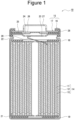
- FIG. 1 is a schematic sectional view of a non-aqueous electrolyte secondary battery as an example of an embodiment.
- a non-aqueous electrolyte secondary battery 10 shown in FIG. 1 includes a winding-type electrode assembly 14 formed by winding a positive electrode 11 and a negative electrode 12 with a pair of separators 13 interposed therebetween, a non-aqueous electrolyte, insulating plates 18 and 19 respectively arranged above and below the electrode assembly 14, and a battery case 15.
- the battery case 15 includes an outer casing 16 that houses the electrode assembly 14, a non-aqueous electrolyte, and the like, and a sealing assembly 17 that closes an opening of the outer casing 16.
- the battery case 15 is not limited to a cylindrical or rectangular metal case, and may be, for example, a resin case (so-called laminate type) formed by laminating a resin sheet.
- the non-aqueous electrolyte includes, for example, a non-aqueous solvent and electrolyte salt dissolved in the non-aqueous solvent.
- a non-aqueous solvent for example, esters, ethers, nitriles, amides, and mixed solvents of two or more thereof are used.
- the non-aqueous solvent may contain a halogen-substituted product in which at least a part of hydrogen in a solvent described above is substituted with a halogen atom such as fluorine.
- the electrolyte salt for example, a lithium salt such as LiPF 6 is used.
- the outer casing 16 is, for example, a bottomed cylindrical metal container.
- a gasket 28 is provided between the outer casing 16 and the sealing assembly 17, to ensure sealability of an inside of the battery.
- the outer casing 16 has, for example, a projecting portion 22 having a part of a side surface projecting inward and supporting the sealing assembly 17.
- the projecting portion 22 is preferably formed in an annular shape in a circumferential direction of the outer casing 16, and supports the sealing assembly 17 on an upper surface thereof.
- the sealing assembly 17 has a structure in which a filter 23, a lower vent member 24, an insulating member 25, an upper vent member 26, and a cap 27 are sequentially stacked from the electrode assembly 14 side.
- Each member constituting the sealing assembly 17 has, for example, a disk shape or a ring shape, and the members excluding the insulating member 25 are electrically connected to each other.
- the lower vent member 24 and the upper vent member 26 are connected to each other at their central portions, and the insulating member 25 is interposed between peripheral edges of the lower vent member 24 and the upper vent member 26.
- the lower vent member 24 deforms to push the upper vent member 26 up toward the cap 27 and breaks, and thus a current pathway between the lower vent member 24 and the upper vent member 26 is cut off.
- the upper vent member 26 breaks, and gas is discharged from an opening of the cap 27.
- a positive electrode lead 20 attached to the positive electrode 11 extends to the sealing assembly 17 side through a through-hole of the insulating plate 18, and a negative electrode lead 21 attached to the negative electrode 12 extends to the bottom side of the outer casing 16 through the outside of the insulating plate 19.
- the positive electrode lead 20 is connected to a lower surface of the filter 23, which is a bottom plate of the sealing assembly 17, by welding or the like, and the cap 27, which is a top plate of the sealing assembly 17 electrically connected to the filter 23, serves as a positive electrode terminal.
- the negative electrode lead 21 is connected to an inner surface of the bottom of the outer casing 16 by welding or the like, and the outer casing 16 serves as a negative electrode terminal.
- FIG. 2 is a schematic sectional view of the electrode assembly as viewed from a winding axis direction.
- the negative electrode 12 is indicated by a solid line
- the positive electrode 11 is indicated by a broken line
- the separator 13 is indicated by a one-dot chain line. Further, in FIG. 2 , a gap between the positive electrode 11, the negative electrode 12, and the separator 13 is exaggerated.
- the electrode assembly 14 is formed by winding the positive electrode 11 and the negative electrode 12 with the pair of separators 13 interposed therebetween.
- the belt-shaped positive electrode 11, the belt-shaped negative electrode 12, and the pair of belt-shaped separators 13 are laminated in an order of one separator 13, the positive electrode 11, the other separator 13, and the negative electrode 12, and then this laminate is spirally wound to produce the electrode assembly 14.
- a longitudinal direction of each electrode is a winding direction
- a width direction of each electrode is a winding axis direction.
- the negative electrode 12 has a non-facing portion 12a that does not face the positive electrode 11 with the pair of separators 13 interposed therebetween, and the non-facing portion 12a is wound 1.5 turns from an inner end in the winding direction (point E1 in FIG. 2 ) that is the winding-start end of the electrode assembly 14. That is, the non-facing portion 12a is a portion from the point E1 shown in FIG. 2 to a point E2 in the winding direction.
- the negative electrode 12 has a facing portion 12b that is wound following the non-facing portion 12a and faces the positive electrode 11 with the pair of separators 13 interposed therebetween.
- a gap is provided between the pair of separators 13 adjacent to the non-facing portion 12a of the negative electrode 12 in order to clarify a configuration of the pair of separators 13, however, in practice, the pair of separators 13 are bonded to each other at this position. A state of the pair of separators 13 at the non-facing portion 12a of the negative electrode 12 will be described later.
- the non-facing portion 12a is wound greater than or equal to 1.5 turns from the inner end in the winding direction of the electrode assembly 14, and is preferably wound by 1.5 turns to 3 turns from the inner end in the winding direction of the electrode assembly 14. Then, the non-facing portion 12a wound greater than or equal to 1.5 turns from the inner end in the winding direction of the electrode assembly 14 relieves stress locally applied to a center of the electrode assembly 14 along with charging and discharging of the battery, so that deformation (buckling) of an electrode plate can be suppressed.
- the positive electrode 11, the negative electrode 12, and the separator 13 constituting the electrode assembly 14 will be described.
- the positive electrode 11 includes a positive electrode current collector and a positive electrode mixture layer formed on a surface of the positive electrode current collector.
- the positive electrode mixture layer is preferably formed on both surfaces of the positive electrode current collector.
- As the positive electrode current collector a foil of a metal such as aluminum which is stable in a potential range of the positive electrode 11, a film having such a metal disposed on a surface layer, or the like can be used.
- the positive electrode mixture layer contains, for example, a positive electrode active material, a binder, a conductive agent, and the like.
- the positive electrode 11 can be produced, for example, by applying a positive electrode mixture slurry containing the positive electrode active material, the binder, the conductive agent, and the like onto the positive electrode current collector, drying a coating film, and then rolling the coating film to form the positive electrode mixture layer on both surfaces of the positive electrode current collector.
- Examples of the positive electrode active material contained in the positive electrode mixture layer include lithium transition metal oxides containing transition metal elements such as Co, Mn, and Ni.
- Examples of the lithium transition metal oxides include Li x CoO 2 , Li x NiO 2 , Li x MnO 2 , Li x Co y Ni 1-y O 2 , LixCo y M 1-y O z , Li x Ni 1-yMy O z , Li x Mn 2 O 4 , Li x Mn 2-y M y O 4 , LiMPO 4 , and Li 2 MPO 4 F
- M is at least one of Na, Mg, Sc, Y, Mn, Fe, Co, Ni, Cu, Zn, Al, Cr, Pb, Sb, and B, 0 ⁇ x ⁇ 1.2, 0 ⁇ y ⁇ 0.9, and 2.0 ⁇ z ⁇ 2.3).
- the positive electrode active material preferably contains a lithium nickel composite oxide such as Li x NiO 2 , Li x Co y Ni 1-y O 2 , or Li x Ni 1- yM y O z (M is at least one of Na, Mg, Sc, Y, Mn, Fe, Co, Ni, Cu, Zn, Al, Cr, Pb, Sb, and B, 0 ⁇ x ⁇ 1.2, 0 ⁇ y ⁇ 0.9, and 2.0 ⁇ z ⁇ 2.3) from the viewpoint of achieving high capacity of the non-aqueous electrolyte secondary battery.
- Inorganic particles such as tungsten oxide, aluminum oxide, and a lanthanoid containing compound may be fixed to a particle surface of the lithium transition metal oxide.
- Examples of the conductive agent contained in the positive electrode mixture layer include carbon materials such as carbon black (CB), acetylene black (AB), Ketjen black, carbon nanotube (CNT), graphene, and graphite. These may be used singly or in combination of two or more kinds thereof.
- binder contained in the positive electrode mixture layer examples include fluorine-based resins such as polytetrafluoroethylene (PTFE) and polyvinylidene fluoride (PVDF), polyacrylonitrile (PAN), polyimide-based resins, acrylic resins, polyolefin-based resins, styrene-butadiene rubber (SBR), carboxymethyl cellulose (CMC) or a salt thereof, polyacrylic acid (PAA) or a salt thereof, polyvinyl alcohol (PVA), and polyethylene oxide (PEO).
- fluorine-based resins such as polytetrafluoroethylene (PTFE) and polyvinylidene fluoride (PVDF), polyacrylonitrile (PAN), polyimide-based resins, acrylic resins, polyolefin-based resins, styrene-butadiene rubber (SBR), carboxymethyl cellulose (CMC) or a salt thereof, polyacrylic acid (PAA) or a salt thereof,
- the negative electrode 12 includes a negative electrode current collector and a negative electrode mixture layer formed on a surface of the negative electrode current collector.
- the negative electrode mixture layer is preferably formed on both surfaces of the negative electrode current collector.
- As the negative electrode current collector a foil of a metal such as copper or a copper alloy which is stable in a potential range of the negative electrode, a film having such a metal disposed on a surface layer, or the like can be used.
- the negative electrode mixture layer contains, for example, a negative electrode active material, a binder, and the like. Examples of the binder include those similar to those for the positive electrode 11.
- the negative electrode 12 can be produced, for example, by applying a negative electrode mixture slurry containing a negative electrode active material, the binder, and the like onto the negative electrode current collector, drying a coating film, and then rolling the coating film to form the negative electrode mixture layer on both surfaces of the negative electrode current collector.
- the negative electrode active material contained in the negative electrode mixture layer is not particularly limited, for example, as long as it can reversibly store and release lithium ions, and examples thereof include a carbon material and a Si-based material
- the carbon material may be, for example, a conventionally known carbon material used as the negative electrode active material, and examples thereof include natural graphite such as flake graphite, massive graphite, and earthy graphite, and artificial graphite such as massive artificial graphite (MAG) and graphitized mesophase carbon microbeads (MCMB).
- natural graphite such as flake graphite, massive graphite, and earthy graphite
- artificial graphite such as massive artificial graphite (MAG) and graphitized mesophase carbon microbeads (MCMB).
- MAG massive artificial graphite
- MCMB graphitized mesophase carbon microbeads
- the Si-based material includes, for example, a lithium ion conducting phase and Si particles dispersed in the lithium ion conducting phase.
- the lithium ion conducting phase includes, for example, at least one of a silicon oxide phase, a silicate phase, and a carbon phase.
- the silicate phase preferably contains, for example, at least one element of alkali metal elements of lithium, sodium, potassium, rubidium, cesium, and francium, and Group 2 elements of the periodic table to which beryllium, magnesium, calcium, strontium, barium, and radium belong from the viewpoint of high lithium ion conductivity and the like.
- the silicate phase is preferably a silicate phase containing lithium (hereinafter, may be referred to as a lithium silicate phase) from the viewpoint of high lithium ion conductivity and the like.
- the Si-based material in which the Si particles are dispersed in the silicon oxide phase is represented by, for example, a general formula SiO x (a range of 0 ⁇ x ⁇ 2 is preferable, and a range of 0.5 ⁇ x ⁇ 1.6 is more preferable).
- the Si-based material in which the Si particles are dispersed in the carbon phase is represented by, for example, a general formula Si x C y (ranges of 0 ⁇ x ⁇ 1 and 0 ⁇ y ⁇ 1 are preferable).
- a conductive layer coated with conductive carbon may be formed on a surface of the Si-based material.
- the conductive layer can be formed by, for example, a CVD method using acetylene, methane, or the like, a method in which coal pitch, petroleum pitch, a phenol resin, or the like is mixed with a silicon-based active material and subjected to heat treatment, or the like.
- a heat treatment apparatus that performs heat treatment, for example, a hot air furnace, a hot press, a lamp, a sheath heater, a ceramic heater, a rotary kiln, or the like can be used.
- the conductive layer may be formed by fixing a conductive filler such as carbon black to a particle surface of the Si-based material using the binder.
- examples of the negative electrode active material that can reversibly store and release lithium ions include Sn, an alloy containing Sn, a Sn-based material such as tin oxide, and a Ti-based material such as lithium titanate.
- FIG. 3 is a schematic sectional view showing an example of the separator.
- the separator 13 has a base material 30 and a functional layer 32 formed on the base material 30.
- the functional layer 32 may be provided on one surface of the base material 30 or may be provided on both surfaces of the base material 30.
- at least one of the pair of separators 13 used in the electrode assembly 14 described above is a separator having the base material 30 and the functional layer 32 formed on the base material 30 as shown in FIG. 3 .
- the other of the pair of separators 13 may be, for example, made of only the base material 30.
- the base material 30 is, for example, a porous sheet having ion permeability and insulating properties, and specific examples thereof include a microporous thin film, a woven fabric, and a nonwoven fabric.
- the material of the base material 30 is not particularly limited, and examples thereof include polyolefins such as polyethylene, polypropylene, a copolymer of polyethylene and an ⁇ -olefin, acrylic resins, polystyrene, polyester, cellulose, polyimide, polyphenylene sulfide, polyether ether ketone, and a fluororesin.
- the functional layer 32 includes a heat resistant layer 34 containing inorganic particles, and resin particles 36 dispersed in the heat resistant layer 34 and having an average particle diameter (D50) larger than a thickness of the heat resistant layer 34.
- the resin particles 36 having the average particle diameter (D50) larger than the thickness of the heat resistant layer 34 form projections 36a projecting from a surface of the heat resistant layer 34.
- Examples of the inorganic particles contained in the heat resistant layer 34 include metal oxide particles, metal nitride particles, metal fluoride particles, and metal carbide particles.
- Examples of the metal oxide particles include aluminum oxide, titanium oxide, magnesium oxide, zirconium oxide, nickel oxide, silicon oxide, and manganese oxide.
- Examples of the metal nitride particles include titanium nitride, boron nitride, aluminum nitride, magnesium nitride, and silicon nitride.
- Examples of the metal fluoride particles include aluminum fluoride, lithium fluoride, sodium fluoride, magnesium fluoride, calcium fluoride, and barium fluoride.
- Examples of the metal carbide particles include silicon carbide, boron carbide, titanium carbide, and tungsten carbide.
- the inorganic particles may be porous aluminosilicates such as zeolite (M 2/n O ⁇ Al 2 0 3 ⁇ xSiO 2 ⁇ yH 2 O, M is a metal element, n is a valence of M, x ⁇ 2, and y ⁇ 0), layered silicates such as talc (Mg 3 Si 4 O 10 (OH) 2 ), minerals such as barium titanate (BaTiO 3 ) and strontium titanate (SrTiO 3 ), and the like. Note that these may be used singly or in combination of two or more kinds thereof.
- zeolite M 2/n O ⁇ Al 2 0 3 ⁇ xSiO 2 ⁇ yH 2 O
- M is a metal element
- n is a valence of M
- layered silicates such as talc (Mg 3 Si 4 O 10 (OH) 2 )
- minerals such as bar
- the average particle diameter (D50) of the inorganic particles is preferably, for example, in a range of 0.1 ⁇ m to 1.0 ⁇ m.
- D50 means a particle size at which a cumulative frequency in a volume-based particle size distribution is 50% from a smallest particle size, and is also called a median diameter.
- the particle size distribution of the inorganic particles can be measured using a laser diffraction type particle size distribution measuring apparatus (for example, MT3000II manufactured by MicrotracBEL Corp.) using water as a dispersion medium.
- the content of the inorganic particles contained in the heat resistant layer 34 is, for example, preferably in a range of 15 mass% to 85 mass%, and more preferably in a range of 30 mass% to 60 mass% based on the total mass of the heat resistant layer 34.
- the thickness of the heat resistant layer 34 is preferably smaller than the thickness of the base material 30, and is, for example, 0.5 ⁇ m to 5 ⁇ m.
- the heat resistant layer 34 preferably further contains the binder.
- the binder has a function of bonding the inorganic particles to each other and the inorganic particles to the base material 30.
- the binder include fluorine-based resins such as polyvinylidene fluoride (PVDF) and polytetrafluoroethylene (PTFE), polyimide-based resins, acrylic resins, polyolefin-based resins, styrene-butadiene rubber (SBR), nitrile-butadiene rubber (NBR), carboxymethyl cellulose (CMC) or a salt thereof, and polyvinyl alcohol (PVA). These may be used singly or in combination of two or more kinds thereof.
- the content of the binder contained in the heat resistant layer 34 is preferably 0.5 to 10 mass%, and more preferably 1 to 5 mass% based on the total mass of the heat resistant layer 34.
- the resin particles 36 dispersed in the heat resistant layer 34 are required to have the average particle diameter (D50) larger than the thickness of the heat resistant layer 34.
- the average particle diameter (D50) of the resin particles 36 depends on the thickness of the heat resistant layer 34, but is preferably, for example, in a range of 2 ⁇ m to 10 ⁇ m.
- the content of the resin particles 36 dispersed in the heat resistant layer 34 is, for example, preferably in a range of 1 mass% to 15 mass%, and more preferably in a range of 3 mass% to 7 mass% based on the total mass of the heat resistant layer 34 from the viewpoint of securing good adhesiveness of the separator 13.
- the number of projections 36a formed by the resin particles 36 is, for example, preferably 10 to 35, and more preferably 15 to 30 in a range of 100 ⁇ m ⁇ 100 ⁇ m when a surface of the functional layer 32 is viewed in a plan view from the viewpoint of securing good adhesiveness of the separator 13.
- the resin particles 36 for example, a known polymer that can be used as the binder can be used.
- a monomer unit constituting the resin particle 36 (polymer) include an aromatic vinyl monomer unit, a (meth)acrylic acid ester monomer unit, and a fluorine-containing monomer unit.
- (meth)acryl means acryl and/or methacryl.
- the phrase that the resin particles 36 (polymer) "contain a monomer unit” means that a repeating unit derived from a monomer is contained in a polymer obtained using the monomer.
- an aromatic vinyl monomer capable of forming the aromatic vinyl monomer unit are not particularly limited, and include styrene, ⁇ -methylstyrene, styrenesulfonic acid, butoxystyrene, and vinylnaphthalene.
- Examples of a (meth)acrylic acid ester monomer capable of forming the (meth)acrylic acid ester monomer unit include: alkyl acrylates such as methyl acrylate, ethyl acrylate, n-propyl acrylate, isopropyl acrylate, butyl acrylates such as n-butyl acrylate and t-butyl acrylate, pentyl acrylate, hexyl acrylate, heptyl acrylate, octyl acrylates such as 2-ethylhexyl acrylate, nonyl acrylate, decyl acrylate, lauryl acrylate, n-tetradecyl acrylate, and stearyl acrylate; and alkyl methacrylate such as methyl methacrylate, ethyl methacrylate, n-propyl methacrylate, isopropyl methacrylate, butyl methacrylate such
- Examples of a fluorine-containing monomer capable of forming the fluorine-containing monomer unit are not particularly limited, and include vinylidene fluoride, tetrafluoroethylene, hexafluoropropylene, vinyl trifluoride chloride, vinyl fluoride, and perfluoroalkyl vinyl ether.
- the resin particle 36 may contain a crosslinkable monomer unit in addition to the above-mentioned monomer unit.
- the crosslinkable monomer unit is a monomer capable of forming a crosslinked structure during or after polymerization by heating or irradiation with an energy ray.
- the monomer capable of forming the crosslinkable monomer unit include a polyfunctional monomer having two or more polymerizable reactive groups in the monomer.
- Examples of such a polyfunctional monomer include: allyl methacrylate, divinyl compounds such as divinylbenzene; di(meth)acrylic acid ester compounds such as diethylene glycol dimethacrylate, ethylene glycol dimethacrylate, diethylene glycol diacrylate, and 1,3-butylene glycol diacrylate; tri(meth)acrylic acid ester compounds such as trimethylolpropane trimethacrylate and trimethylolpropane triacrylate; and ethylenically unsaturated monomers containing an epoxy group such as allyl glycidyl ether and glycidyl methacrylate.
- the resin particles 36 can be prepared, for example, by polymerizing a monomer composition containing the above-described monomer in an aqueous solvent such as water. Then, a polymerization mode is not particularly limited, and may be, for example, a suspension polymerization method, an emulsion polymerization aggregation method, a pulverization method, or the like. Further, as a polymerization reaction, any reaction such as radical polymerization or living radical polymerization can be used.
- other compounding materials such as a chain transfer agent, a polymerization modifier, a polymerization reaction retarder, a reactive fluidizing agent, a filler, a flame retardant, an antiaging agent, and a colorant can be compounded in an arbitrary compounding amount.
- the separator 13 of the present embodiment An example of a method for producing the separator 13 of the present embodiment will be described.
- the inorganic particles, a heat-resistant resin, the resin particles 36, water as the dispersion medium, and other components (for example, the binder or the like) used as necessary are mixed to prepare a functional layer slurry composition.
- functional layer slurry is applied onto the base material and then dried, so that the separator 13 of the present embodiment can be produced.
- FIG. 4 is a view showing a state of the positive electrode, the negative electrode, and the separator when an inner end side of the electrode assembly in the winding direction is developed.
- the separator 13 constituting the electrode assembly 14 is disposed such that the functional layer 32 faces the positive electrode 11. Therefore, as shown in FIG. 4 , in the non-facing portion 12a of the negative electrode 12, the pair of separators 13 are bonded to each other, and a large space S1 is formed between the negative electrode 12 and the separator 13 of the non-facing portion 12a.
- FIG. 5 is a view showing a state of the positive electrode, the negative electrode, and the separator when an inner end side of a conventional electrode assembly in the winding direction is developed.
- a separator 13a constituting a conventional electrode assembly 14a does not include the functional layer 32 (for example, it is composed only of the base material 30). Therefore, in the non-facing portion 12a of the negative electrode 12, the pair of separators 13a are not bonded to each other, and a space between the negative electrode 12 and the separator 13a of the non-facing portion 12a is a narrow space S2. Since the non-aqueous electrolyte is easily held in such a narrow space S2, it is considered that the non-aqueous electrolyte is easily decomposed on the non-facing portion 12a of the negative electrode 12.
- a positive electrode mixture slurry 100 parts by mass of LiNi 0.88 Co 0.09 Al 0.03 O 2 , 1 part by mass of acetylene black (AB), and 0.9 parts by mass of polyvinylidene fluoride (PVDF) were mixed, and an appropriate amount of N-methyl-2-pyrrolidone (NMP) was added to prepare a positive electrode mixture slurry.
- NMP N-methyl-2-pyrrolidone
- the positive electrode mixture slurry was applied to both surfaces of an aluminum foil having a thickness of 15 ⁇ m, and a coating film was dried. Then, the coating film was rolled using a roller and then cut into a predetermined electrode size to produce a positive electrode having a positive electrode mixture layer formed on both surfaces of a positive electrode current collector. An exposed portion where the positive electrode mixture layer was not formed and the positive electrode current collector was exposed was provided at a central portion of the positive electrode in the longitudinal direction, and an aluminum positive electrode lead was welded to the exposed portion.
- a porous base material made of polyethylene having a thickness of 12 ⁇ m was prepared.
- ⁇ -Al 2 O 3 powders(inorganic particles) having an average particle diameter (D50) of 0.8 ⁇ m, acrylic resin particles having an average particle diameter (D50) of 3 ⁇ m and including a copolymer of 2-ethylhexyl acrylate and styrene (hereinafter, acrylic resin particles), and an acrylic binder (a binder) were mixed at a solid content mass ratio of 100:6:5, and then an appropriate amount of water was added so that a solid content concentration was 10 mass% to prepare functional layer slurry.
- the functional layer slurry was applied to an entire area of one surface of the base material using a microgravure coater, and the coating film was heated and dried in an oven at 50°C for 4 hours to obtain a separator having a functional layer having a heat resistant layer formed on the one surface of the base material.
- a surface of the functional layer of the separator was observed with a scanning electron microscope, a plurality of projections of the resin particles protruding from the heat resistant layer were observed. The plurality of projections were similarly observed in other Examples.
- the separator, the positive electrode, the separator, and the negative electrode were laminated in this order, and then the laminate was spirally wound to produce a winding-type electrode assembly.
- a pair of separators were arranged such that the functional layer of each of the pair of separators faced the positive electrode.
- the number of windings of the electrode assembly was set to 18 times based on the positive electrode. Further, a non-facing portion of the negative electrode was wound 1.5 turns from the inner end in the winding direction of the electrode assembly.
- VC vinylene carbonate
- EC ethylene carbonate
- DMC dimethyl carbonate
- LiPF 6 lithium hexafluorophosphate
- Insulating plates were respectively arranged above and below the electrode assembly, and the electrode assembly was housed in an exterior can.
- the negative electrode lead was welded to a bottom of a bottomed cylindrical exterior can, and the positive electrode lead was welded to a sealing assembly.
- an opening of the exterior can was sealed with the sealing assembly through a gasket, and then the exterior can was allowed to stand in a thermostatic chamber at 60°C for 15 hours to produce a non-aqueous electrolyte secondary battery.
- a non-aqueous electrolyte secondary battery was produced in the same manner as in Example 1 except that the acrylic resin particles having an average particle diameter (D50) of 3 ⁇ m were replaced with acrylic resin particles having an average particle diameter (D50) of 5 ⁇ m in production of the separator.
- a non-aqueous electrolyte secondary battery was produced in the same manner as in Example 1 except that the acrylic resin particles having an average particle diameter (D50) of 3 ⁇ m were replaced with acrylic resin particles having an average particle diameter (D50) of 7 ⁇ m in production of the separator.
- a non-aqueous electrolyte secondary battery was produced in the same manner as in Example 1 except that the graphite powder was changed from 88 parts by mass to 94 parts by mass, and the Si-based material was changed from 12 parts by mass to 6 parts by mass in production of the negative electrode.
- a non-aqueous electrolyte secondary battery was produced in the same manner as in Example 1 except that the graphite powder was changed from 88 parts by mass to 94 parts by mass, and the Si-based material was changed from 12 parts by mass to 6 parts by mass in production of the negative electrode, and winding of the non-facing portion of the negative electrode was changed from 1.5 turns to 2.5 turns in production of the electrode assembly.
- a non-aqueous electrolyte secondary battery was produced in the same manner as in Example 1 except that the graphite powder was changed from 88 parts by mass to 94 parts by mass, and the Si-based material was changed from 12 parts by mass to 6 parts by mass in production of the negative electrode, and the acrylic resin particles having an average particle diameter (D50) of 3 ⁇ m were changed to acrylic resin particles having an average particle diameter (D50) of 5 ⁇ m in production of the separator.
- a non-aqueous electrolyte secondary battery was produced in the same manner as in Example 1 except that the graphite powder was changed from 88 parts by mass to 94 parts by mass, and the Si-based material was changed from 12 parts by mass to 6 parts by mass in production of the negative electrode, and the acrylic resin particles having an average particle diameter (D50) of 3 ⁇ m were changed to acrylic resin particles having an average particle diameter (D50) of 7 ⁇ m in production of the separator.
- a non-aqueous electrolyte secondary battery was produced in the same manner as in Example 1 except that the graphite powder was changed from 88 parts by mass to 94 parts by mass, and the Si-based material was changed from 12 parts by mass to 6 parts by mass in production of the negative electrode, and the acrylic resin particles having an average particle diameter (D50) of 3 ⁇ m were changed to acrylic resin particles having an average particle diameter (D50) of 10 ⁇ m in production of the separator.
- a non-aqueous electrolyte secondary battery was produced in the same manner as in Example 1 except that the graphite powder was changed from 88 parts by mass to 94 parts by mass, and the Si-based material was changed from 12 parts by mass to 6 parts by mass in production of the negative electrode, and winding of the non-facing portion of the negative electrode was changed from 1.5 turns to 1 turn in production of the electrode assembly.
- a non-aqueous electrolyte secondary battery was produced in the same manner as in Example 1 except that the graphite powder was changed from 88 parts by mass to 94 parts by mass, and the Si-based material was changed from 12 parts by mass to 6 parts by mass in production of the negative electrode, and a porous base material made of polyethylene having a thickness of 12 ⁇ m was used as the separator.
- a non-aqueous electrolyte secondary battery was produced in the same manner as in Example 1 except that a porous base material made of polyethylene having a thickness of 12 ⁇ m was used as the separator.
- the above charging and discharging was set as one cycle, and 500 cycles were performed while a pause time of 20 minutes was inserted between cycles.
- the non-aqueous electrolyte secondary battery after 500 cycles was charged at the constant current of 0.3It until the battery voltage reached 4.2 V, and then charged at a constant voltage of 4.2 V until the current reached 0.02It to enter a charged state.
- the non-aqueous electrolyte secondary battery in this charged state was subjected to sectional observation near a winding center of the electrode assembly using an X-ray CT apparatus (SMX-225CT FPD HR manufactured by Shimadzu Corporation). As shown in FIG.
- Example 1 Winding (Turns) of negative electrode non-facing portion Graphite : Si-based material : CNT Mass ratio Acrylic resin particles Electrode plate deformation Initial charge-discharge efficiency (%) Presence or absence D50
- Example 1 1.5 turns 88 : 12 : 0.56 Presence 3 ⁇ 87
- Example 2 1.5 turns 88 : 12 : 0.56 Presence 5 ⁇ 86
- Example 3 1.5 turns 88 : 12 : 0.56 Presence 7 ⁇ 86
- Example 4 1.5 turns 94 : 6 : 0.56 Presence 3 ⁇ 94
- Example 5 2.5 turns 94 : 6 : 0.56 Presence 3 ⁇ 94
- Example 6 1.5 turns 94 : 6 : 0.56 Presence 5 ⁇ 93
- Example 7 1.5 turns 94 : 6 : 0.56 Presence 7 ⁇ 91
- Example 8 1.5 turns 94 : 6 : 0.56 Presence 10 ⁇ 89 Comparative Example 1 1 turn 94 : 6 : 0.56 Presence 3 ⁇ 91
- Example 1 the initial charge-discharge efficiency showed a high value of greater than or equal to 85%, and the electrode plate deformation did not occur.
- Comparative Example 1 the initial charge-discharge efficiency showed a high value, but the electrode plate deformation occurred.
- Comparative Example 2 the electrode plate deformation did not occur, but the initial charge-discharge efficiency was less than 85%, which was a low value.
- Comparative Example 3 the initial charge-discharge efficiency was low, and the electrode plate deformation occurred.
Landscapes
- Chemical & Material Sciences (AREA)
- Chemical Kinetics & Catalysis (AREA)
- Electrochemistry (AREA)
- General Chemical & Material Sciences (AREA)
- Engineering & Computer Science (AREA)
- Inorganic Chemistry (AREA)
- Composite Materials (AREA)
- Materials Engineering (AREA)
- Manufacturing & Machinery (AREA)
- Ceramic Engineering (AREA)
- Secondary Cells (AREA)
Applications Claiming Priority (2)
| Application Number | Priority Date | Filing Date | Title |
|---|---|---|---|
| JP2022133102 | 2022-08-24 | ||
| PCT/JP2023/029513 WO2024043145A1 (fr) | 2022-08-24 | 2023-08-15 | Batterie secondaire à électrolyte non aqueux |
Publications (2)
| Publication Number | Publication Date |
|---|---|
| EP4579864A1 true EP4579864A1 (fr) | 2025-07-02 |
| EP4579864A4 EP4579864A4 (fr) | 2026-01-21 |
Family
ID=90013250
Family Applications (1)
| Application Number | Title | Priority Date | Filing Date |
|---|---|---|---|
| EP23857258.0A Pending EP4579864A4 (fr) | 2022-08-24 | 2023-08-15 | Batterie secondaire à électrolyte non aqueux |
Country Status (4)
| Country | Link |
|---|---|
| EP (1) | EP4579864A4 (fr) |
| JP (1) | JPWO2024043145A1 (fr) |
| CN (1) | CN119631221A (fr) |
| WO (1) | WO2024043145A1 (fr) |
Families Citing this family (2)
| Publication number | Priority date | Publication date | Assignee | Title |
|---|---|---|---|---|
| JPWO2024247841A1 (fr) * | 2023-05-31 | 2024-12-05 | ||
| WO2026048340A1 (fr) * | 2024-08-28 | 2026-03-05 | パナソニックIpマネジメント株式会社 | Batterie secondaire à électrolyte non aqueux |
Family Cites Families (9)
| Publication number | Priority date | Publication date | Assignee | Title |
|---|---|---|---|---|
| JP2007123237A (ja) * | 2005-09-29 | 2007-05-17 | Sanyo Electric Co Ltd | 非水電解質電池、非水電解質電池用電極、及びこの非水電解質電池用電極の製造方法 |
| JP2013137946A (ja) | 2011-12-28 | 2013-07-11 | Panasonic Corp | 非水電解液二次電池 |
| JP6216203B2 (ja) * | 2013-10-09 | 2017-10-18 | 日立オートモティブシステムズ株式会社 | 捲回式二次電池 |
| KR20150057481A (ko) * | 2013-11-19 | 2015-05-28 | 삼성에스디아이 주식회사 | 리튬 전지용 세퍼레이터, 이를 포함하는 리튬 전지, 및 상기 리튬 전지의 제조방법 |
| US11264649B2 (en) * | 2016-12-22 | 2022-03-01 | Sanyo Electric Co., Ltd. | Cylindrical nonaqueous electrolyte secondary battery |
| EP3979354A4 (fr) * | 2019-06-03 | 2023-01-18 | Zeon Corporation | Séparateur comprenant une couche fonctionnelle pour élément électrochimique, et élément électrochimique |
| WO2020262437A1 (fr) * | 2019-06-28 | 2020-12-30 | 三洋電機株式会社 | Accumulateur à électrolyte non aqueux cylindrique |
| WO2021161842A1 (fr) * | 2020-02-12 | 2021-08-19 | 日本ゼオン株式会社 | Corps multicouche pour éléments électrochimiques, et élément électrochimique |
| TWI795101B (zh) * | 2020-11-30 | 2023-03-01 | 日商旭化成股份有限公司 | 蓄電裝置用分隔件及包含其之蓄電裝置 |
-
2023
- 2023-08-15 EP EP23857258.0A patent/EP4579864A4/fr active Pending
- 2023-08-15 JP JP2024542772A patent/JPWO2024043145A1/ja active Pending
- 2023-08-15 CN CN202380059054.2A patent/CN119631221A/zh active Pending
- 2023-08-15 WO PCT/JP2023/029513 patent/WO2024043145A1/fr not_active Ceased
Also Published As
| Publication number | Publication date |
|---|---|
| EP4579864A4 (fr) | 2026-01-21 |
| JPWO2024043145A1 (fr) | 2024-02-29 |
| WO2024043145A1 (fr) | 2024-02-29 |
| CN119631221A (zh) | 2025-03-14 |
Similar Documents
| Publication | Publication Date | Title |
|---|---|---|
| KR102586846B1 (ko) | 리튬 이차 전지 | |
| EP4579864A1 (fr) | Batterie secondaire à électrolyte non aqueux | |
| EP4597679A1 (fr) | Batterie secondaire à électrolyte non aqueux | |
| CN112005422B (zh) | 非水电解质二次电池 | |
| EP4333153A1 (fr) | Batterie secondaire à électrolyte non aqueux | |
| CN112563482B (zh) | 非水电解质二次电池用正极活性物质和非水电解质二次电池 | |
| EP4564577A1 (fr) | Batterie secondaire à électrolyte non aqueux | |
| EP4625569A1 (fr) | Batterie secondaire | |
| US12166207B2 (en) | Positive electrode active material for nonaqueous electrolyte secondary batteries, and nonaqueous electrolyte secondary battery | |
| JP2025028269A (ja) | 非水電解質二次電池用正極活物質、及び非水電解質二次電池 | |
| US20250309470A1 (en) | Non-aqueous electrolyte secondary battery | |
| EP4625570A1 (fr) | Batterie secondaire | |
| EP4597680A1 (fr) | Batterie secondaire à électrolyte non aqueux | |
| JP2002075356A (ja) | 非水二次電池 | |
| US20250343276A1 (en) | Non-aqueous electrolyte secondary battery | |
| US12300815B2 (en) | Positive electrode active material for nonaqueous electrolyte secondary batteries, and nonaqueous electrolyte secondary battery | |
| WO2025225626A1 (fr) | Séparateur pour batterie secondaire à électrolyte non aqueux | |
| WO2025225627A1 (fr) | Séparateur pour batterie secondaire à électrolyte non aqueux | |
| WO2024247841A1 (fr) | Batterie secondaire cylindrique | |
| WO2024161977A1 (fr) | Batterie secondaire à électrolyte non aqueux | |
| WO2024181189A1 (fr) | Batterie secondaire cylindrique | |
| WO2025225625A1 (fr) | Batterie secondaire à électrolyte non aqueux | |
| WO2024181044A1 (fr) | Électrode pour batterie secondaire à électrolyte non aqueux, et batterie secondaire à électrolyte non aqueux | |
| WO2025249166A1 (fr) | Batterie secondaire à électrolyte non aqueux | |
| WO2023189507A1 (fr) | Matériau actif d'électrode positive pour batterie secondaire à électrolyte non aqueux, et batterie secondaire à électrolyte non aqueux |
Legal Events
| Date | Code | Title | Description |
|---|---|---|---|
| STAA | Information on the status of an ep patent application or granted ep patent |
Free format text: STATUS: THE INTERNATIONAL PUBLICATION HAS BEEN MADE |
|
| PUAI | Public reference made under article 153(3) epc to a published international application that has entered the european phase |
Free format text: ORIGINAL CODE: 0009012 |
|
| STAA | Information on the status of an ep patent application or granted ep patent |
Free format text: STATUS: REQUEST FOR EXAMINATION WAS MADE |
|
| 17P | Request for examination filed |
Effective date: 20250219 |
|
| AK | Designated contracting states |
Kind code of ref document: A1 Designated state(s): AL AT BE BG CH CY CZ DE DK EE ES FI FR GB GR HR HU IE IS IT LI LT LU LV MC ME MK MT NL NO PL PT RO RS SE SI SK SM TR |
|
| DAV | Request for validation of the european patent (deleted) | ||
| DAX | Request for extension of the european patent (deleted) | ||
| REG | Reference to a national code |
Ref country code: DE Ref legal event code: R079 Free format text: PREVIOUS MAIN CLASS: H01M0010058700 Ipc: H01M0004587000 |
|
| A4 | Supplementary search report drawn up and despatched |
Effective date: 20251219 |
|
| RIC1 | Information provided on ipc code assigned before grant |
Ipc: H01M 4/587 20100101AFI20251215BHEP Ipc: H01M 4/36 20060101ALI20251215BHEP Ipc: H01M 4/38 20060101ALI20251215BHEP Ipc: H01M 50/414 20210101ALI20251215BHEP Ipc: H01M 50/434 20210101ALI20251215BHEP Ipc: H01M 50/443 20210101ALI20251215BHEP Ipc: H01M 50/446 20210101ALI20251215BHEP Ipc: H01M 50/451 20210101ALI20251215BHEP Ipc: H01M 50/46 20210101ALI20251215BHEP Ipc: H01M 10/0525 20100101ALI20251215BHEP Ipc: H01M 10/42 20060101ALI20251215BHEP |