EP4579931A1 - Kathodenfolie, anodenfolie, batteriezelle, batterie und elektrische vorrichtung - Google Patents
Kathodenfolie, anodenfolie, batteriezelle, batterie und elektrische vorrichtung Download PDFInfo
- Publication number
- EP4579931A1 EP4579931A1 EP23916716.6A EP23916716A EP4579931A1 EP 4579931 A1 EP4579931 A1 EP 4579931A1 EP 23916716 A EP23916716 A EP 23916716A EP 4579931 A1 EP4579931 A1 EP 4579931A1
- Authority
- EP
- European Patent Office
- Prior art keywords
- positive
- negative
- tab
- electrode plate
- battery cell
- Prior art date
- Legal status (The legal status is an assumption and is not a legal conclusion. Google has not performed a legal analysis and makes no representation as to the accuracy of the status listed.)
- Pending
Links
Images


Classifications
-
- H—ELECTRICITY
- H01—ELECTRIC ELEMENTS
- H01M—PROCESSES OR MEANS, e.g. BATTERIES, FOR THE DIRECT CONVERSION OF CHEMICAL ENERGY INTO ELECTRICAL ENERGY
- H01M10/00—Secondary cells; Manufacture thereof
- H01M10/04—Construction or manufacture in general
- H01M10/0431—Cells with wound or folded electrodes
-
- H—ELECTRICITY
- H01—ELECTRIC ELEMENTS
- H01M—PROCESSES OR MEANS, e.g. BATTERIES, FOR THE DIRECT CONVERSION OF CHEMICAL ENERGY INTO ELECTRICAL ENERGY
- H01M10/00—Secondary cells; Manufacture thereof
- H01M10/05—Accumulators with non-aqueous electrolyte
- H01M10/052—Li-accumulators
-
- H—ELECTRICITY
- H01—ELECTRIC ELEMENTS
- H01M—PROCESSES OR MEANS, e.g. BATTERIES, FOR THE DIRECT CONVERSION OF CHEMICAL ENERGY INTO ELECTRICAL ENERGY
- H01M10/00—Secondary cells; Manufacture thereof
- H01M10/05—Accumulators with non-aqueous electrolyte
- H01M10/052—Li-accumulators
- H01M10/0525—Rocking-chair batteries, i.e. batteries with lithium insertion or intercalation in both electrodes; Lithium-ion batteries
-
- H—ELECTRICITY
- H01—ELECTRIC ELEMENTS
- H01M—PROCESSES OR MEANS, e.g. BATTERIES, FOR THE DIRECT CONVERSION OF CHEMICAL ENERGY INTO ELECTRICAL ENERGY
- H01M10/00—Secondary cells; Manufacture thereof
- H01M10/60—Heating or cooling; Temperature control
- H01M10/65—Means for temperature control structurally associated with the cells
- H01M10/655—Solid structures for heat exchange or heat conduction
- H01M10/6553—Terminals or leads
-
- H—ELECTRICITY
- H01—ELECTRIC ELEMENTS
- H01M—PROCESSES OR MEANS, e.g. BATTERIES, FOR THE DIRECT CONVERSION OF CHEMICAL ENERGY INTO ELECTRICAL ENERGY
- H01M4/00—Electrodes
- H01M4/02—Electrodes composed of, or comprising, active material
- H01M4/13—Electrodes for accumulators with non-aqueous electrolyte, e.g. for lithium-accumulators; Processes of manufacture thereof
- H01M4/131—Electrodes based on mixed oxides or hydroxides, or on mixtures of oxides or hydroxides, e.g. LiCoOx
-
- H—ELECTRICITY
- H01—ELECTRIC ELEMENTS
- H01M—PROCESSES OR MEANS, e.g. BATTERIES, FOR THE DIRECT CONVERSION OF CHEMICAL ENERGY INTO ELECTRICAL ENERGY
- H01M4/00—Electrodes
- H01M4/02—Electrodes composed of, or comprising, active material
- H01M4/13—Electrodes for accumulators with non-aqueous electrolyte, e.g. for lithium-accumulators; Processes of manufacture thereof
- H01M4/136—Electrodes based on inorganic compounds other than oxides or hydroxides, e.g. sulfides, selenides, tellurides, halogenides or LiCoFy
-
- H—ELECTRICITY
- H01—ELECTRIC ELEMENTS
- H01M—PROCESSES OR MEANS, e.g. BATTERIES, FOR THE DIRECT CONVERSION OF CHEMICAL ENERGY INTO ELECTRICAL ENERGY
- H01M4/00—Electrodes
- H01M4/02—Electrodes composed of, or comprising, active material
- H01M4/36—Selection of substances as active materials, active masses, active liquids
- H01M4/58—Selection of substances as active materials, active masses, active liquids of inorganic compounds other than oxides or hydroxides, e.g. sulfides, selenides, tellurides, halogenides or LiCoFy; of polyanionic structures, e.g. phosphates, silicates or borates
- H01M4/5825—Oxygenated metallic salts or polyanionic structures, e.g. borates, phosphates, silicates, olivines
-
- H—ELECTRICITY
- H01—ELECTRIC ELEMENTS
- H01M—PROCESSES OR MEANS, e.g. BATTERIES, FOR THE DIRECT CONVERSION OF CHEMICAL ENERGY INTO ELECTRICAL ENERGY
- H01M4/00—Electrodes
- H01M4/02—Electrodes composed of, or comprising, active material
- H01M4/64—Carriers or collectors
- H01M4/66—Selection of materials
- H01M4/661—Metal or alloys, e.g. alloy coatings
-
- H—ELECTRICITY
- H01—ELECTRIC ELEMENTS
- H01M—PROCESSES OR MEANS, e.g. BATTERIES, FOR THE DIRECT CONVERSION OF CHEMICAL ENERGY INTO ELECTRICAL ENERGY
- H01M50/00—Constructional details or processes of manufacture of the non-active parts of electrochemical cells other than fuel cells, e.g. hybrid cells
- H01M50/20—Mountings; Secondary casings or frames; Racks, modules or packs; Suspension devices; Shock absorbers; Transport or carrying devices; Holders
- H01M50/204—Racks, modules or packs for multiple batteries or multiple cells
- H01M50/207—Racks, modules or packs for multiple batteries or multiple cells characterised by their shape
- H01M50/209—Racks, modules or packs for multiple batteries or multiple cells characterised by their shape adapted for prismatic or rectangular cells
-
- H—ELECTRICITY
- H01—ELECTRIC ELEMENTS
- H01M—PROCESSES OR MEANS, e.g. BATTERIES, FOR THE DIRECT CONVERSION OF CHEMICAL ENERGY INTO ELECTRICAL ENERGY
- H01M50/00—Constructional details or processes of manufacture of the non-active parts of electrochemical cells other than fuel cells, e.g. hybrid cells
- H01M50/50—Current conducting connections for cells or batteries
- H01M50/531—Electrode connections inside a battery casing
-
- H—ELECTRICITY
- H01—ELECTRIC ELEMENTS
- H01M—PROCESSES OR MEANS, e.g. BATTERIES, FOR THE DIRECT CONVERSION OF CHEMICAL ENERGY INTO ELECTRICAL ENERGY
- H01M50/00—Constructional details or processes of manufacture of the non-active parts of electrochemical cells other than fuel cells, e.g. hybrid cells
- H01M50/50—Current conducting connections for cells or batteries
- H01M50/543—Terminals
- H01M50/552—Terminals characterised by their shape
- H01M50/553—Terminals adapted for prismatic, pouch or rectangular cells
-
- H—ELECTRICITY
- H01—ELECTRIC ELEMENTS
- H01M—PROCESSES OR MEANS, e.g. BATTERIES, FOR THE DIRECT CONVERSION OF CHEMICAL ENERGY INTO ELECTRICAL ENERGY
- H01M4/00—Electrodes
- H01M4/02—Electrodes composed of, or comprising, active material
- H01M2004/021—Physical characteristics, e.g. porosity, surface area
-
- H—ELECTRICITY
- H01—ELECTRIC ELEMENTS
- H01M—PROCESSES OR MEANS, e.g. BATTERIES, FOR THE DIRECT CONVERSION OF CHEMICAL ENERGY INTO ELECTRICAL ENERGY
- H01M4/00—Electrodes
- H01M4/02—Electrodes composed of, or comprising, active material
- H01M2004/026—Electrodes composed of, or comprising, active material characterised by the polarity
- H01M2004/027—Negative electrodes
-
- H—ELECTRICITY
- H01—ELECTRIC ELEMENTS
- H01M—PROCESSES OR MEANS, e.g. BATTERIES, FOR THE DIRECT CONVERSION OF CHEMICAL ENERGY INTO ELECTRICAL ENERGY
- H01M4/00—Electrodes
- H01M4/02—Electrodes composed of, or comprising, active material
- H01M2004/026—Electrodes composed of, or comprising, active material characterised by the polarity
- H01M2004/028—Positive electrodes
-
- H—ELECTRICITY
- H01—ELECTRIC ELEMENTS
- H01M—PROCESSES OR MEANS, e.g. BATTERIES, FOR THE DIRECT CONVERSION OF CHEMICAL ENERGY INTO ELECTRICAL ENERGY
- H01M2220/00—Batteries for particular applications
- H01M2220/20—Batteries in motive systems, e.g. vehicle, ship, plane
-
- H—ELECTRICITY
- H01—ELECTRIC ELEMENTS
- H01M—PROCESSES OR MEANS, e.g. BATTERIES, FOR THE DIRECT CONVERSION OF CHEMICAL ENERGY INTO ELECTRICAL ENERGY
- H01M4/00—Electrodes
- H01M4/02—Electrodes composed of, or comprising, active material
- H01M4/13—Electrodes for accumulators with non-aqueous electrolyte, e.g. for lithium-accumulators; Processes of manufacture thereof
- H01M4/139—Processes of manufacture
- H01M4/1391—Processes of manufacture of electrodes based on mixed oxides or hydroxides, or on mixtures of oxides or hydroxides, e.g. LiCoOx
-
- H—ELECTRICITY
- H01—ELECTRIC ELEMENTS
- H01M—PROCESSES OR MEANS, e.g. BATTERIES, FOR THE DIRECT CONVERSION OF CHEMICAL ENERGY INTO ELECTRICAL ENERGY
- H01M4/00—Electrodes
- H01M4/02—Electrodes composed of, or comprising, active material
- H01M4/13—Electrodes for accumulators with non-aqueous electrolyte, e.g. for lithium-accumulators; Processes of manufacture thereof
- H01M4/139—Processes of manufacture
- H01M4/1397—Processes of manufacture of electrodes based on inorganic compounds other than oxides or hydroxides, e.g. sulfides, selenides, tellurides, halogenides or LiCoFy
-
- Y—GENERAL TAGGING OF NEW TECHNOLOGICAL DEVELOPMENTS; GENERAL TAGGING OF CROSS-SECTIONAL TECHNOLOGIES SPANNING OVER SEVERAL SECTIONS OF THE IPC; TECHNICAL SUBJECTS COVERED BY FORMER USPC CROSS-REFERENCE ART COLLECTIONS [XRACs] AND DIGESTS
- Y02—TECHNOLOGIES OR APPLICATIONS FOR MITIGATION OR ADAPTATION AGAINST CLIMATE CHANGE
- Y02E—REDUCTION OF GREENHOUSE GAS [GHG] EMISSIONS, RELATED TO ENERGY GENERATION, TRANSMISSION OR DISTRIBUTION
- Y02E60/00—Enabling technologies; Technologies with a potential or indirect contribution to GHG emissions mitigation
- Y02E60/10—Energy storage using batteries
Definitions
- secondary batteries have been widely used in the fields such as mobile electronic devices, household appliances, and electric vehicles. With continuous development of products using secondary batteries, higher requirements have also been imposed on the capacity, energy density, charge/discharge rate, and cycling stability of secondary batteries in various fields.
- the present application provides a positive electrode plate, a negative electrode plate, a battery cell, a battery, and an electric apparatus, which can provide a reasonable adjustment range for a size of a tab and layout distribution of the tab in an electrode plate while increasing the volumetric energy density of the battery cell and ensuring that an internal temperature of the battery cell does not exceed a threshold.
- a width of a root of each positive tab along an MD direction is m1, measured in mm; a thickness of the root of each positive tab is d1, measured in mm; along the MD direction, a size between central axes of two adjacent positive tabs is b1, measured in mm; a conductivity of the positive current collector is S1, measured in S/m; a width of the positive active material layer along a TD direction is a1, measured in mm; and a mass per unit area of the positive active material layer is CW1, measured in g/1540.25 mm 2 .
- size specifications of each positive tab and the design of a distance between adjacent positive tabs are adjusted according to the design parameter of each positive tab, ensuring that the battery cell has a current carrying capability matching with the volumetric energy density on the premise of increasing the volumetric energy density of the battery cell, thereby ensuring that a local temperature rise of the corresponding battery cell in a fixed charging process does not exceed a threshold.
- the value of the design parameter of each positive tab satisfies Fc ⁇ 0.4.
- the design parameter of each positive tab is further optimized, ensuring that the design of the positive tab ensures that a local temperature rise of the battery cell in a fixed charging process does not exceed a threshold while ensuring that the volumetric energy density of the battery cell reaches a certain level.
- a ratio of the mass per unit area of the positive active material layer to the thickness of the positive current collector is taken as a positive electrode plate factor, and a value of the positive electrode plate factor satisfies 17 ⁇ ⁇ c ⁇ 50, where ⁇ c represents the positive electrode plate factor, measured in g/1540.25 mm 3 .
- the value of the positive electrode plate factor is limited to ensure that the positive current collector 110 is maintained above a certain strength without problems such as plate breakage caused by cold pressing and internal brittle fracture of the battery cell, and also to control the mass per unit area of the positive active material layer within a certain value range without the problems such as serious coating cracking, poor weight distribution uniformity and easy demolding of the electrode plate, thereby ensuring the manufacturing efficiency and cost advantage of the battery cell.
- value ranges of various parameters of the positive tab, the positive active material layer and the positive current collector are determined, and within the above value ranges, the stability of product performance of the battery cell is ensured.
- the positive active material layer includes a lithium iron phosphate material.
- the positive tab of the lithium iron phosphate secondary battery is designed, which can effectively increase the volumetric energy density of the battery cell to 300 Wh/L, thereby ensuring that a local temperature rise of the battery cell in a fixed charging process does not exceed 60°C.
- the present application provides a negative electrode plate, including a negative current collector and a negative active material layer disposed on at least one side of the negative current collector, where the negative current collector includes a negative body portion and at least one negative tab disposed at one end of the negative body portion.
- the value of the design parameter of each positive tab satisfies Fc ⁇ 0.1; and/or the value of the design parameter of each negative tab satisfies Fa ⁇ 0.02.
- a direction or a positional relationship indicated by the terms such as “center”, “longitudinal”, “transverse”, “length”, “width”, “thickness”, “up”, “down”, “before”, “after”, “left”, “right”, “vertical”, “horizontal”, “top”, “bottom”, “in”, “out”, “clockwise”, “counterclockwise”, “axial”, “radial”, and “circumferential” is a direction or positional relationship based on the illustration in the drawings, and is merely intended for ease or brevity of description of embodiments of the present application, but not intended to indicate or imply that the indicated device or component is necessarily located in the specified direction or constructed or operated in the specified direction. Therefore, such terms are not to be understood as a limitation on embodiments of the present application.
- the technical solutions described in the embodiments of the present application are applicable to positive electrode plates, negative electrode pates, battery cells, batteries, and electric apparatuses.
- the battery cell disclosed in the present application can be applied to lithium-ion secondary batteries and can also applied to other energy storage batteries. This is not limited in the present application.
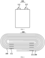
- the present application provides a positive electrode plate 100, including a positive current collector 110 and a positive active material layer 120 disposed on at least one side of the positive current collector 110.
- the positive current collector 110 includes a positive body portion 111 and at least one positive tab 112 disposed at one end of the positive body portion 111.
- the positive electrode plate 100 includes the positive current collector 110 and the positive active material layer 120.
- the positive current collector 110 is typically made of a metal material. Taking a lithium-ion battery as an example, the positive current collector 110 may be an aluminum foil.
- the positive active material layer 120 is applied onto at least one side of the positive current collector 110. Taking a lithium-ion battery as an example, the positive active material layer 120 may be made of a material of lithium cobaltate, lithium iron phosphate, ternary lithium, lithium manganate, or the like.
- the positive active material layer 120 may be disposed on only one side of the positive current collector 110 or disposed on two sides of the positive current collector 110.
- the positive body portion 111 is a part, that is coated with the positive active material layer 120, of the positive current collector 110.
- the positive tab 112 is a part, that protrudes from the positive body portion 111, of the positive current collector 110.
- the positive tab 112 may be disposed at only one end of the positive body portion 111 or disposed at two ends of the positive body portion 111.
- One end of the positive body portion 111 may be provided with only one positive tab 112 or provided with a plurality of positive tabs 112 that are laminated. It can be understood that the number of the positive tabs 112 in the present application can be adjusted as required.
- the central axis M of the positive tab represents a line connecting centers of all cross sections of the positive tab 112.
- the root of each positive tab 112 represents a part, that is connected to the positive body portion 111, of the positive tab 112. In one or more embodiments of the present application, a length of the root of each positive tab 112 along the TD direction accounts for less than 50% of a length of each positive tab 112 along the TD direction. Specifically, the length of the root of each positive tab 112 along the TD direction accounts for less than 40%, 30%, 20%, or 10% of the length of each positive tab 112 along the TD direction, which is reasonably set as required.
- the TD direction Transverse Direction
- a length direction of the electrode plate is perpendicular to the TD direction, which is an MD direction (Machine Direction).
- a cross-sectional area of the root of each positive tab 112, a coating weight of the positive active material layer corresponding to each positive tab 112, and the like can be adjusted to a reasonable range based on the design parameter of each positive tab 112, ensuring that the local temperature rise of the battery cell in a fixed charging process does not exceed a threshold.
- size specifications of each positive tab 112 and the design of a distance between adjacent positive tabs 112 are adjusted according to the design parameter of each positive tab 112, ensuring that the battery cell has a current carrying capability matching with the volumetric energy density on the premise of increasing the volumetric energy density of the battery cell, thereby ensuring that a local temperature rise of the corresponding battery cell in a fixed charging process does not exceed a threshold.
- the value of the design parameter of each positive tab 112 satisfies Fc ⁇ 0.4.
- a lower limit of the value of the design parameter of each positive tab 112 represents that the current carrying capacity which each positive tab 112 bears has a certain threshold. If the value of the design parameter of each positive tab 112 exceeds the lower limit, each positive tab 112 bears an excessively large current carrying capacity and excessively small current carrying capability, joule heat at the root of the positive tab 112 is increased, and the temperature at the root of the positive tab 112 exceeds the temperature threshold, causing rapid performance deterioration of the battery cell.
- An upper limit of the value of the design parameter of each positive tab 112 corresponds to a critical point at which the current carrying capability is the largest and the current carrying capacity is the smallest, mainly ensuring that the design of each positive tab 112 can satisfy the fast charging capability of the battery cell.
- the design parameter of each positive tab 112 is further optimized, ensuring that the design of the positive tab 112 ensures that a local temperature rise of the battery cell in a fixed charging process does not exceed a threshold while ensuring that the volumetric energy density of the battery cell reaches a certain level.
- a ratio of the mass per unit area of the positive active material layer 120 to the thickness of the positive current collector 110 is taken as a positive electrode plate factor, and a value of the positive electrode plate factor satisfies 17 ⁇ ⁇ c ⁇ 50, where ⁇ c represents the positive electrode plate factor, measured in g/1540.25 mm 3 .
- the positive electrode plate factor represents a variable of the design parameter of each positive tab 112.
- the positive electrode plate factor indicates that the mass per unit area of the positive active material layer 120 has a correlation with the thickness of the positive current collector 110, and the two are not two independent variables and cannot each take an arbitrary value.
- the value of the positive electrode plate factor is limited to ensure that the positive current collector 110 is maintained above a certain strength without problems such as plate breakage caused by cold pressing and internal brittle fracture of the battery cell, and also to control the mass per unit area of the positive active material layer 120 within a certain value range without the problems such as serious coating cracking, poor weight distribution uniformity and easy demolding of the electrode plate, thereby ensuring the manufacturing efficiency and cost advantage of the battery cell. It can be understood that within the value range, a larger positive electrode plate factor indicates thicker coating and higher volumetric energy density of the battery cell.
- a width of a root of each negative tab 212 along an MD direction is m2, measured in mm.
- a thickness of the root of each negative tab 212 is d2, measured in mm.
- a size between central axes N of two adjacent negative tabs is b2, measured in mm.
- a conductivity of the negative current collector 210 is S2, measured in S/m.
- a width of the negative active material layer 220 along a TD direction is a2, measured in mm.
- a mass per unit area of the negative active material layer 220 is CW2, measured in g/1540.25 mm 2 .
- the negative electrode plate 200 includes the negative current collector 210 and the negative active material layer 220.
- the negative current collector 210 is typically made of a metal material. Taking a lithium-ion battery as an example, the negative current collector 210 may be a copper foil.
- the negative active material layer 220 is applied onto at least one side of the negative current collector 210. Taking a lithium-ion battery as an example, the negative active material layer 220 may be made of a carbon or silicon material.
- the negative active material layer 220 may be disposed on only one side of the negative current collector 210 or disposed on two sides of the negative current collector 210.
- the negative body portion 211 is a part, that is coated with the negative active material layer 220, of the negative current collector 210.
- the negative tab 212 is part, that protrudes from the negative body portion 211, of the negative current collector 210.
- the negative tab 212 may be disposed at only one end of the negative body portion 211 or disposed at two ends of the negative body portion 211.
- One end of the negative body portion 211 may be provided with only one negative tab 212 or provided with a plurality of negative tabs 212 that are laminated. It can be understood that the number of the negative tabs 212 in the present application can be adjusted as required.
- the central axis N of the negative tab represents a line connecting centers of all cross sections of the negative tab 212.
- a cross-sectional area of the root of each negative tab 212, a coating weight of the negative active material layer corresponding to each negative tab 212, and the like can be adjusted to a reasonable range based on the design parameter of each negative tab 212, ensuring that the local temperature rise of the battery cell in a fixed charging process does not exceed a threshold.
- m 2 ⁇ d 2 represents the cross-sectional area of the root of the negative tab 212
- m2 ⁇ d2 ⁇ S 2 represents the current carrying capability of each negative tab 212
- CW 2 ⁇ a 2 ⁇ b 2 represents a current carrying capacity which each negative tab 212 needs to bear.
- a lower limit of Fa corresponds to a critical point at which each negative tab 212 has the smallest current carrying capability and bears the largest current carrying capacity, mainly ensuring that the temperature rise at the root of the negative tab 212 does not exceed 60°C.
- An upper limit of the value of the design parameter of each negative tab 212 corresponds to a critical point at which the current carrying capability is the largest and the current carrying capacity is the smallest, mainly ensuring that the design of each negative tab 212 can satisfy the fast-charging capability of the battery cell.
- a ratio of the mass per unit area of the negative active material layer 220 to the thickness of the negative current collector 210 is taken as a negative electrode plate factor, and a value of the negative electrode plate factor satisfies 15 ⁇ ⁇ a ⁇ 85, where ⁇ a represents the negative electrode plate factor, measured in g/1540.25 mm 3 .
- a lower limit of the value of the negative electrode plate factor corresponds to a critical point at which the negative active material layer 220 has the smallest mass per unit area and the negative current collector 210 has the largest thickness, mainly ensuring that the volumetric energy density of the battery cell can reach a certain numerical value.
- An upper limit of the value of the negative electrode plate factor corresponds to a critical point at which the negative active material layer 220 has the largest mass per unit area and the negative current collector 210 has the smallest thickness.
- the value of the negative electrode plate factor is limited to ensure that the negative current collector 210 is maintained above a certain strength without problems such as plate breakage caused by cold pressing and internal brittle fracture of the battery cell, and also to control the mass per unit area of the negative active material layer 220 within a certain value range without the problems such as serious coating cracking, poor weight distribution uniformity and easy demolding of the electrode plate, thereby ensuring the manufacturing efficiency and cost advantage of the battery cell. It can be understood that within the value range, a larger positive electrode plate factor indicates thicker coating and higher volumetric energy density of the battery cell.
- the inventors of the present application determines the value ranges of various parameters of the negative tab 212, the negative active material layer 220 and the negative current collector 210 on the premise of increasing the volumetric energy density (such as 300 Wh/L) of the battery cell and ensuring that a local temperature rise of the battery cell in a fixed charging process does not exceed a threshold (such as 60°C); and within the above value ranges, the stability of product performance of the battery cell is ensured.
- a threshold such as 60°C
- the negative current collector 210 includes a negative body portion 211 and at least one negative tab 212 disposed at one end of the negative body portion 211.
- a wound battery cell 300 is provided. It can be understood that the battery cell 300 may alternatively be a laminated type, which can be set as required and is not limited in the present application.
- the battery cell 300 is a lithium iron phosphate secondary battery.
- the volumetric energy density of the battery cell 300 is ⁇ 300 Wh/L. After the battery cell 300 is charged at a rate of 3C at a room temperature for 6 min, maximum temperatures of the root of the positive tab 112 and the root of the negative tab 212 of the battery cell 300 are ⁇ 60°C.
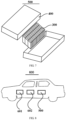
- FIG 7 is a schematic structural diagram of a battery provided in the present application.
- the design parameter Fc of the positive tab and the design parameter Fa of the negative tab are within the value ranges provided in the present application, one of the positive electrode plate factor ⁇ c and the negative electrode plate factor ⁇ a is within the value range, and the other is less than the minimum value, so the volumetric energy density of the battery cell is less than 300 Wh/L, while the maximum temperature at the root of the positive tab and the maximum temperature at the root of the negative tab are both below 60°C.
- the positive electrode plate factor ⁇ c and the negative electrode plate factor ⁇ a are within the value ranges provided in the present application, the design parameter Fc of the positive tab is within the value range, and the design parameter Fa of the negative tab is less than the minimum value, so the volumetric energy density of the battery cell is greater than 300 Wh/L, the maximum temperature at the root of each positive tab is below 60°C, but the maximum temperature at the root of each negative tab is above 60°C.
- the positive electrode plate factor ⁇ c and the negative electrode plate factor ⁇ a are within the value ranges provided in the present application, the design parameter Fc of the positive tab is not within the value range, and the design parameter Fa of the negative tab is within the value range, so the volumetric energy density of the battery cell is greater than 300 Wh/L, the maximum temperature at the root of each positive tab is above 60°C, but the maximum temperature at the root of each negative tab is not above 60°C.
- the disclosed system, apparatus, and method may be implemented in other manners.
- the described apparatus embodiments are merely illustrative.
- the unit division is merely logical function division and other division manners may be used in actual implementation.
- a plurality of units or components may be combined or integrated into another system, or some features may be ignored or not be performed.
Landscapes
- Chemical & Material Sciences (AREA)
- Chemical Kinetics & Catalysis (AREA)
- Electrochemistry (AREA)
- General Chemical & Material Sciences (AREA)
- Engineering & Computer Science (AREA)
- Materials Engineering (AREA)
- Inorganic Chemistry (AREA)
- Manufacturing & Machinery (AREA)
- Crystallography & Structural Chemistry (AREA)
- Battery Electrode And Active Subsutance (AREA)
- Connection Of Batteries Or Terminals (AREA)
- Secondary Cells (AREA)
- Cell Electrode Carriers And Collectors (AREA)
Applications Claiming Priority (1)
| Application Number | Priority Date | Filing Date | Title |
|---|---|---|---|
| PCT/CN2023/072808 WO2024152228A1 (zh) | 2023-01-18 | 2023-01-18 | 阴极极片、阳极极片、电池单体、电池和用电装置 |
Publications (2)
| Publication Number | Publication Date |
|---|---|
| EP4579931A1 true EP4579931A1 (de) | 2025-07-02 |
| EP4579931A4 EP4579931A4 (de) | 2025-12-03 |
Family
ID=91955007
Family Applications (1)
| Application Number | Title | Priority Date | Filing Date |
|---|---|---|---|
| EP23916716.6A Pending EP4579931A4 (de) | 2023-01-18 | 2023-01-18 | Kathodenfolie, anodenfolie, batteriezelle, batterie und elektrische vorrichtung |
Country Status (6)
| Country | Link |
|---|---|
| US (1) | US12424614B2 (de) |
| EP (1) | EP4579931A4 (de) |
| JP (1) | JP2025533571A (de) |
| KR (1) | KR20250049429A (de) |
| CN (1) | CN119968737B (de) |
| WO (1) | WO2024152228A1 (de) |
Families Citing this family (1)
| Publication number | Priority date | Publication date | Assignee | Title |
|---|---|---|---|---|
| CN119133576A (zh) * | 2024-11-12 | 2024-12-13 | 宁德时代新能源科技股份有限公司 | 电池单体、电池装置以及用电装置 |
Family Cites Families (19)
| Publication number | Priority date | Publication date | Assignee | Title |
|---|---|---|---|---|
| JP2006260786A (ja) * | 2005-03-15 | 2006-09-28 | Hitachi Maxell Ltd | 非水電解質二次電池 |
| TWI270994B (en) * | 2005-12-29 | 2007-01-11 | Ind Tech Res Inst | High rate capability design of lithium ion secondary battery |
| JP5127271B2 (ja) * | 2007-03-12 | 2013-01-23 | 株式会社東芝 | 捲回型電極電池およびその製造方法 |
| JP5311861B2 (ja) * | 2008-03-31 | 2013-10-09 | 三洋電機株式会社 | リチウム二次電池 |
| US8142928B2 (en) * | 2008-06-04 | 2012-03-27 | Basvah Llc | Systems and methods for rechargeable battery collector tab configurations and foil thickness |
| JP2011204660A (ja) * | 2010-03-04 | 2011-10-13 | Sanyo Electric Co Ltd | リチウム二次電池 |
| JP2015011930A (ja) * | 2013-07-01 | 2015-01-19 | トヨタ自動車株式会社 | 非水電解質二次電池 |
| CN110085920A (zh) * | 2018-01-26 | 2019-08-02 | 上海瑞浦青创新能源有限公司 | 多极耳卷绕式锂离子电池极片及其制备方法 |
| US11322807B2 (en) * | 2018-07-20 | 2022-05-03 | Ruipu Energy Co., Ltd. | Electrode plate and battery cell of wound lithium-ion battery and method for manufacturing same |
| CN111755656A (zh) * | 2019-03-26 | 2020-10-09 | 宁德新能源科技有限公司 | 极片、电芯及电池 |
| WO2021200373A1 (ja) * | 2020-03-31 | 2021-10-07 | 株式会社Gsユアサ | 蓄電素子 |
| CN114976512A (zh) * | 2021-02-23 | 2022-08-30 | 北京小米移动软件有限公司 | 极片、电芯结构、锂电池以及电子设备 |
| CN113113738A (zh) * | 2021-03-24 | 2021-07-13 | 福建南平延平区南孚新能源科技有限公司 | 一种多极耳电池 |
| CN121097359A (zh) * | 2021-08-19 | 2025-12-09 | 宁德新能源科技有限公司 | 电极组件、电池和用电设备 |
| CN216903255U (zh) | 2022-01-05 | 2022-07-05 | 宁德时代新能源科技股份有限公司 | 电极组件、电池单体、电池及用电装置 |
| CN114497434A (zh) * | 2022-01-13 | 2022-05-13 | 重庆市紫建新能源有限公司 | 一种电池极片、锂电池及生产工艺 |
| CN217009337U (zh) | 2022-03-25 | 2022-07-19 | 厦门海辰新能源科技有限公司 | 锂离子电池 |
| CN115000345B (zh) * | 2022-06-27 | 2023-03-17 | 楚能新能源股份有限公司 | 电池极片及其生产方法、包含该极片的电池芯包和电池 |
| CN114927834B (zh) * | 2022-07-01 | 2024-01-09 | 齐鲁中科光物理与工程技术研究院 | 一种电池极片、电极芯和二次电池 |
-
2023
- 2023-01-18 CN CN202380067385.0A patent/CN119968737B/zh active Active
- 2023-01-18 KR KR1020257009903A patent/KR20250049429A/ko active Pending
- 2023-01-18 WO PCT/CN2023/072808 patent/WO2024152228A1/zh not_active Ceased
- 2023-01-18 EP EP23916716.6A patent/EP4579931A4/de active Pending
- 2023-01-18 JP JP2025517751A patent/JP2025533571A/ja active Pending
-
2025
- 2025-01-17 US US19/029,492 patent/US12424614B2/en active Active
Also Published As
| Publication number | Publication date |
|---|---|
| CN119968737B (zh) | 2025-11-14 |
| KR20250049429A (ko) | 2025-04-11 |
| US12424614B2 (en) | 2025-09-23 |
| WO2024152228A1 (zh) | 2024-07-25 |
| CN119968737A (zh) | 2025-05-09 |
| EP4579931A4 (de) | 2025-12-03 |
| US20250167207A1 (en) | 2025-05-22 |
| JP2025533571A (ja) | 2025-10-07 |
Similar Documents
| Publication | Publication Date | Title |
|---|---|---|
| US20240243444A1 (en) | Electrode plate, electrode assembly, battery cell, battery, and electric device | |
| US20240372153A1 (en) | Battery cell, battery, electric device, and electrode assembly and manufacturing method thereof | |
| EP3316391B1 (de) | Batteriesystem, grundplatte für ein batteriesystem und elektrofahrzeug | |
| EP4148876A1 (de) | Batterie, stromverbrauchsvorrichtung und verfahren und vorrichtung zur herstellung einer batterie | |
| US20250105455A1 (en) | Electrode assembly, battery cell, battery, and electric device | |
| KR20110118797A (ko) | 전지 탭 구조 | |
| EP4213273B1 (de) | Ladeverfahren für batterie sowie batterie und elektrische energievorrichtung | |
| KR20160140457A (ko) | 조전지의 제조 방법 | |
| EP4258441A1 (de) | Batterie, stromverbrauchsvorrichtung und verfahren zur herstellung einer batterie | |
| EP2779296A1 (de) | Sekundärbatterie mit mehreren elektrodenanordnungen | |
| US20230093575A1 (en) | Lithium ion battery, battery pack, electric vehicle, and energy storage device | |
| US12424614B2 (en) | Positive electrode plate, negative electrode plate, battery cell, battery, and electric apparatus | |
| US20240363889A1 (en) | Electrode assembly, battery cell, battery, and electric device | |
| KR20250145661A (ko) | 전지, 전기 기기 및 에너지 저장 기기 | |
| EP4258445A1 (de) | Batterie, elektrische vorrichtung sowie verfahren und vorrichtung zur herstellung der batterie | |
| EP4266464A1 (de) | Batterie, elektrische vorrichtung sowie verfahren und vorrichtung zur herstellung der batterie | |
| EP4657633A1 (de) | Batterie und elektrische vorrichtung | |
| US12218330B2 (en) | Battery, power consumption device, and method and device for producing battery | |
| EP4258419A1 (de) | Batterie, elektrische vorrichtung sowie batterieherstellungsverfahren und -vorrichtung | |
| EP4471949A1 (de) | Batteriezelle, batterie und elektrische vorrichtung | |
| WO2013106748A1 (en) | Lead-acid battery design having versatile form factor | |
| EP4391120A1 (de) | Stromkollektor, elektrodenfolie und herstellungsverfahren dafür, elektrodenanordnung und sekundärbatterie | |
| EP4254609A1 (de) | Batterie, elektrische vorrichtung sowie verfahren und vorrichtung zur herstellung der batterie | |
| EP4528847A1 (de) | Elektrodenanordnung, sekundärbatterie und elektrische vorrichtung | |
| EP4528840A1 (de) | Elektrodenanordnung, sekundärbatterie und elektrische vorrichtung |
Legal Events
| Date | Code | Title | Description |
|---|---|---|---|
| STAA | Information on the status of an ep patent application or granted ep patent |
Free format text: STATUS: THE INTERNATIONAL PUBLICATION HAS BEEN MADE |
|
| PUAI | Public reference made under article 153(3) epc to a published international application that has entered the european phase |
Free format text: ORIGINAL CODE: 0009012 |
|
| STAA | Information on the status of an ep patent application or granted ep patent |
Free format text: STATUS: REQUEST FOR EXAMINATION WAS MADE |
|
| 17P | Request for examination filed |
Effective date: 20250326 |
|
| AK | Designated contracting states |
Kind code of ref document: A1 Designated state(s): AL AT BE BG CH CY CZ DE DK EE ES FI FR GB GR HR HU IE IS IT LI LT LU LV MC ME MK MT NL NO PL PT RO RS SE SI SK SM TR |
|
| A4 | Supplementary search report drawn up and despatched |
Effective date: 20251104 |
|
| RIC1 | Information provided on ipc code assigned before grant |
Ipc: H01M 50/531 20210101AFI20251029BHEP Ipc: H01M 10/04 20060101ALI20251029BHEP Ipc: H01M 10/6553 20140101ALI20251029BHEP Ipc: H01M 50/553 20210101ALI20251029BHEP Ipc: H01M 4/131 20100101ALI20251029BHEP Ipc: H01M 4/136 20100101ALI20251029BHEP Ipc: H01M 4/1391 20100101ALI20251029BHEP Ipc: H01M 4/1397 20100101ALI20251029BHEP Ipc: H01M 4/58 20100101ALI20251029BHEP Ipc: H01M 4/66 20060101ALI20251029BHEP Ipc: H01M 10/0525 20100101ALI20251029BHEP Ipc: H01M 50/209 20210101ALI20251029BHEP Ipc: H01M 4/02 20060101ALI20251029BHEP |
|
| DAV | Request for validation of the european patent (deleted) | ||
| DAX | Request for extension of the european patent (deleted) |