EP4579940A1 - Batteriezelle, batterie und elektrische vorrichtung - Google Patents
Batteriezelle, batterie und elektrische vorrichtung Download PDFInfo
- Publication number
- EP4579940A1 EP4579940A1 EP23918992.1A EP23918992A EP4579940A1 EP 4579940 A1 EP4579940 A1 EP 4579940A1 EP 23918992 A EP23918992 A EP 23918992A EP 4579940 A1 EP4579940 A1 EP 4579940A1
- Authority
- EP
- European Patent Office
- Prior art keywords
- wall part
- battery cell
- support frame
- liquid retaining
- section
- Prior art date
- Legal status (The legal status is an assumption and is not a legal conclusion. Google has not performed a legal analysis and makes no representation as to the accuracy of the status listed.)
- Pending
Links
Images



Classifications
-
- H—ELECTRICITY
- H01—ELECTRIC ELEMENTS
- H01M—PROCESSES OR MEANS, e.g. BATTERIES, FOR THE DIRECT CONVERSION OF CHEMICAL ENERGY INTO ELECTRICAL ENERGY
- H01M50/00—Constructional details or processes of manufacture of the non-active parts of electrochemical cells other than fuel cells, e.g. hybrid cells
- H01M50/10—Primary casings; Jackets or wrappings
- H01M50/102—Primary casings; Jackets or wrappings characterised by their shape or physical structure
- H01M50/103—Primary casings; Jackets or wrappings characterised by their shape or physical structure prismatic or rectangular
-
- H—ELECTRICITY
- H01—ELECTRIC ELEMENTS
- H01M—PROCESSES OR MEANS, e.g. BATTERIES, FOR THE DIRECT CONVERSION OF CHEMICAL ENERGY INTO ELECTRICAL ENERGY
- H01M50/00—Constructional details or processes of manufacture of the non-active parts of electrochemical cells other than fuel cells, e.g. hybrid cells
- H01M50/60—Arrangements or processes for filling or topping-up with liquids; Arrangements or processes for draining liquids from casings
- H01M50/668—Means for preventing spilling of liquid or electrolyte, e.g. when the battery is tilted or turned over
-
- H—ELECTRICITY
- H01—ELECTRIC ELEMENTS
- H01M—PROCESSES OR MEANS, e.g. BATTERIES, FOR THE DIRECT CONVERSION OF CHEMICAL ENERGY INTO ELECTRICAL ENERGY
- H01M50/00—Constructional details or processes of manufacture of the non-active parts of electrochemical cells other than fuel cells, e.g. hybrid cells
- H01M50/50—Current conducting connections for cells or batteries
- H01M50/531—Electrode connections inside a battery casing
- H01M50/533—Electrode connections inside a battery casing characterised by the shape of the leads or tabs
-
- H—ELECTRICITY
- H01—ELECTRIC ELEMENTS
- H01M—PROCESSES OR MEANS, e.g. BATTERIES, FOR THE DIRECT CONVERSION OF CHEMICAL ENERGY INTO ELECTRICAL ENERGY
- H01M50/00—Constructional details or processes of manufacture of the non-active parts of electrochemical cells other than fuel cells, e.g. hybrid cells
- H01M50/60—Arrangements or processes for filling or topping-up with liquids; Arrangements or processes for draining liquids from casings
- H01M50/673—Containers for storing liquids; Delivery conduits therefor
- H01M50/682—Containers for storing liquids; Delivery conduits therefor accommodated in battery or cell casings
-
- H—ELECTRICITY
- H01—ELECTRIC ELEMENTS
- H01M—PROCESSES OR MEANS, e.g. BATTERIES, FOR THE DIRECT CONVERSION OF CHEMICAL ENERGY INTO ELECTRICAL ENERGY
- H01M2220/00—Batteries for particular applications
- H01M2220/20—Batteries in motive systems, e.g. vehicle, ship, plane
-
- H—ELECTRICITY
- H01—ELECTRIC ELEMENTS
- H01M—PROCESSES OR MEANS, e.g. BATTERIES, FOR THE DIRECT CONVERSION OF CHEMICAL ENERGY INTO ELECTRICAL ENERGY
- H01M50/00—Constructional details or processes of manufacture of the non-active parts of electrochemical cells other than fuel cells, e.g. hybrid cells
- H01M50/50—Current conducting connections for cells or batteries
- H01M50/531—Electrode connections inside a battery casing
- H01M50/538—Connection of several leads or tabs of wound or folded electrode stacks
-
- Y—GENERAL TAGGING OF NEW TECHNOLOGICAL DEVELOPMENTS; GENERAL TAGGING OF CROSS-SECTIONAL TECHNOLOGIES SPANNING OVER SEVERAL SECTIONS OF THE IPC; TECHNICAL SUBJECTS COVERED BY FORMER USPC CROSS-REFERENCE ART COLLECTIONS [XRACs] AND DIGESTS
- Y02—TECHNOLOGIES OR APPLICATIONS FOR MITIGATION OR ADAPTATION AGAINST CLIMATE CHANGE
- Y02E—REDUCTION OF GREENHOUSE GAS [GHG] EMISSIONS, RELATED TO ENERGY GENERATION, TRANSMISSION OR DISTRIBUTION
- Y02E60/00—Enabling technologies; Technologies with a potential or indirect contribution to GHG emissions mitigation
- Y02E60/10—Energy storage using batteries
Definitions
- the present application relates to the field of battery technology, and specifically, to a battery cell, a battery, and an electric device.
- Embodiments of the present application provide a battery cell, a battery, and an electric device, which can effectively improve the use safety of the battery cell.
- the negative electrode active material may be a negative electrode active material for a battery cell well known in the art.
- the negative electrode active material may include at least one of the following materials: artificial graphite, natural graphite, soft carbon, hard carbon, silicon-based material, tin-based material, lithium titanate, etc.
- the material of the positive current collector may be aluminum, and the material of the negative current collector may be copper.
- the main material of the separator may be at least one selected from glass fiber, non-woven fabric, polyethylene, polypropylene, polyvinylidene fluoride, and ceramic.
- the separation member is solid electrolyte.
- the solid electrolyte is arranged between the positive electrode and the negative electrode, and plays the role of transporting ions and isolating the positive electrode from negative electrode.
- the battery cell further includes an electrolyte, which plays a role in conducting ions between the positive electrode and negative electrode.
- an electrolyte which plays a role in conducting ions between the positive electrode and negative electrode.
- the present application has no particular limitation on the type of electrolyte, which can be selected according to needs.
- the electrolyte may be liquid, gelatinous or solid.
- the electrode assembly is in a wound structure.
- the positive electrode sheet and the negative electrode sheet are wound into the wound structure.
- the electrode assembly is in a laminated structure.
- the shape of the electrode assembly may be cylindrical, flat, or polygonal, etc.
- the battery cell may include a shell.
- the shell is used to package components such as the electrode assembly and the electrolyte.
- the shell may be a steel shell, an aluminum shell, a plastic shell (such as polypropylene), a composite metal shell (such as a copper-aluminum composite shell) or an aluminum-plastic film, etc.
- the battery cell may be a cylindrical battery cell, a prismatic battery cell, a soft-pack battery cell or a battery cell of other shapes
- the prismatic battery cell includes a square-shell battery cell, a blade-shaped battery cell, a multi-prismatic battery
- the multi-prismatic battery is, for example, a hexagonal battery, etc., which are not specifically limited in the present application.
- the battery mentioned in embodiments of the present application refers to a single physical module that includes one or more battery cells to provide higher voltage and capacity.
- the battery may be a battery module.
- the multiple battery cells are arranged and fixed to form a battery module.
- the battery may be a battery pack.
- the battery pack includes a box and battery cell(s), and the battery cell(s) or the battery module is accommodated in the box.
- the box may be provided as a portion of the chassis structure of the vehicle.
- a portion of the box may become at least a portion of the floor of the vehicle, or a portion of the box may become at least a portion of the cross beams and the longitudinal beams of the vehicle.
- the battery cell may be an energy storage device.
- the energy storage device includes an energy storage container, an energy storage cabinet, etc.
- the battery which has outstanding advantages such as high energy density, low environmental pollution, high power density, long service life, wide application range, and small self-discharge coefficient, is an important part of the development of new energy today. However, with the continuous development of battery technology, higher requirements are also put forward for the use safety of battery.
- the shell of the battery cell usually includes a casing and an end cover, and the end cover covers the opening of the casing.
- the electrode terminal is usually assembled to the end cover of the battery cell, so that when the end cover covers the casing, the electrode terminal, the current collecting member and the tabs of the electrode assembly may be stacked and welded to each other first to achieve electrical connection between the electrode terminal and the electrode assembly, so that the electrode terminal is used as the output electrode of the battery cell to achieve inputting or outputting of electric energy for the battery cell, and finally the end cover is connected to the casing.
- the electrolytic solution may be free between the current collecting member and the end cover.
- the electrolytic solution inside the battery cell is very likely to flow out from the weak points or welding points between the electrode terminal and the end cover and between the end cover and the casing, thereby causing the phenomenon that the electrolytic solution in the battery cell leaks, resulting in a greater safety hazard during the use of the battery cell.
- the battery cell includes a shell, electrode terminals, electrode assemblies, a support frame and liquid retention layers.
- the shell has a wall part, and the electrode terminals are provided at the wall part.
- the electrode assemblies are accommodated in the shell.
- the electrode assembly has a main body and tabs. In the thickness direction of the wall part, the tabs protrude from an end of the main body facing the wall part and is connected to the electrode terminals.
- the support frame is provided between the wall part and the main body.
- the support frame is configured to support the main body.
- the liquid retaining layers are provided at the support frame, and the liquid retaining layers are configured to absorb and store the electrolytic solution in the shell.
- the support frame is provided between the wall part and the main body, and the support frame may support the main body of the electrode assembly, that is, the battery cell is provided inverted, such that the wall part of the battery cell provided with the electrode assembly is provided facing downwards, to make the end of the electrode assembly provided with the tabs face downwards, so as to enable the support frame to alleviate the situation where local stress occurs on the main body of the electrode assembly, to reduce the risk of damage to the main body of the electrode assembly.
- the liquid retaining layers can absorb and store the electrolytic solution located at the bottom of the shell and free between the support frame and the wall part.
- the phenomenon of the electrolytic solution flowing out of the shell can be alleviated, and the outflow amount of the electrolytic solution can be reduced, which is beneficial to reduce the use risk of the battery cell caused by leakage during use and further can effectively improve the use safety of the battery cell.
- the battery cell disclosed in the embodiments of the present application can be used in, but is not limited to, vehicles, ships, aircraft or other electric devices.
- the power supply system of the electric device composed of battery cells, batteries, etc., disclosed in the present application, may be used. In this way, it is beneficial to alleviate the problem of electrolytic solution leakage during the use of the battery cell, so as to improve the use safety of the battery cell.
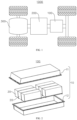
- the box 10 is used to provide an assembly space for the battery cells 20, and the box 10 may be in a variety of structures.
- the box 10 may include a first box body 11 and a second box body 12.
- the first box body 11 and the second box body 12 cover each other.
- the first box body 11 and the second box body 12 jointly define the assembly space for accommodating the battery cells 20.
- the second box body 12 may be in a hollow structure with one side open, and the first box body 11 may be in a plate-like structure.
- the first box body 11 covers the open side of the second box body 12, so that the first box body 11 and the second box body 12 jointly define an assembly space; and the first box body 11 and the second box body 12 may also be both in a hollow structure with one side open, and the open side of the first box body 11 covers the open side of the second box body 12.
- the box 10 formed by the first box body 11 and the second box body 12 may be in various shapes, such as a cylinder, a cuboid and so on. Exemplarily, in FIG. 2 , the box 10 is in the shape of a cuboid.
- FIG. 4 is a structural exploded view of a battery cell 20 provided by some embodiments of the present application
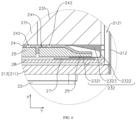
- FIG. 5 is a sectional view of a battery cell 20 provided by some embodiments of the present application.
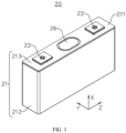
- the present application provides a battery cell 20.
- the battery cell 20 includes a shell 21, electrode terminals 22, electrode assemblies 23, a support frame 24 and liquid retaining layers 25.
- the shell 21 has a wall part 211, and the electrode terminals 22 are provided at the wall part 211.
- the electrode assemblies 23 are accommodated in the shell 21.
- the electrode assembly 23 has a main body 231 and tabs 232.
- the shell 21 may be further used to accommodate the electrolytic solution.
- the shell 21 may be in various structural form, such as a cylinder, a cuboid and so on.
- the shell 21 may be made of a variety of materials, such as copper, iron, aluminum, steel, aluminum alloy, etc.
- the shell 21 may include a casing 212 and an end cover 213, where an accommodation cavity 2121 is formed inside the casing 212, and the accommodation cavity 2121 is used to accommodate the electrode assemblies 23, and the accommodation cavity 2121 has an opening 2122, that is, the casing 212 is in a hollow structure with an opening 2122 at one end, and the end cover 213 covers the opening 2122 of the casing 212 and forms a sealed connection to form a sealed space for accommodating the electrode assemblies 23 and the electrolyte.
- the wall part 211 for mounting the electrode terminals 22 may be the end cover 213 or a wall of the casing 212.
- the wall part 211 is the end cover 213.
- the structure of the battery cell 20 is not limited thereto.
- the wall part 211 may also be a bottom wall of the casing 212 provided opposite to the end cover 213, or a side wall of the casing 212 adjacent to and abutting against the end cover 213.
- the electrode assemblies 23 When assembling the battery cell 20, the electrode assemblies 23 may be placed in the casing 212 first, followed by filling the electrolytic solution into the casing 212 and then making the end cover 213 cover the opening 2122 of the casing 212, to complete the assembly of the battery cell 20.
- the casing 212 may be in various shapes, such as a cylinder, a cuboid, or polygonal/prismatic structure and so on.
- the shape of the casing 212 may be determined by the specific shape of the electrode assembly 23. For example, if the electrode assembly 23 is in a cylinder structure, the casing 212 may be selected to be in a cylinder structure; and if the electrode assembly 23 is in a cuboid structure, the casing 212 may be selected to be in a cuboid structure.
- the end cover 213 may be in various structures.
- the end cover 213 is a plate-like structure or a hollow structure with one end open, or the like.
- the battery cell 212 is in a cuboid structure.
- the shell 21 is not only limited to the above structure.
- the shell 21 may also be in other structure.
- the shell 21 may include a casing 212 and two end covers 213.
- the casing 212 is a hollow structure with openings 2122 at opposite sides thereof.
- One end cover 213 correspondingly covers one opening 2122 of the casing 212 and forms a sealed connection to form a sealed space for accommodating the electrode assemblies 23 and the electrolyte. That is, the casing 212 is provided with openings 2122 at opposite sides thereof, and the two end covers 213 respectively covers the two sides of the casing 212 to seal the corresponding openings 2122.
- the electrode assembly 23 is a component in the battery cell 20 where electrochemical reactions occur.
- the main body 231 of the electrode assembly 23 may include a positive electrode sheet, a negative electrode sheet, and a separator.
- the electrode assembly 23 may be in various structures.
- the main body 231 of the electrode assembly 23 may be a wound structure formed by winding the positive electrode sheet, the separator and the negative electrode sheet, or may be in a laminated structure formed by stacking the positive electrode sheet, the separator and the negative electrode sheet.
- the tab 232 of the electrode assembly 23 is a component formed by stacking and connecting the regions of the positive electrode sheet not coated with the positive electrode active material layer or a component formed by stacking and connecting the regions of the negative electrode sheet not coated with the negative electrode active material layer.
- the shell 21 of the battery cell 20 is provided with two electrode assemblies 23, and the main bodies 231 of the two electrode assemblies 23 are stacked in the first direction Y, that is, the main bodies 231 of the two electrode assemblies 23 are stacked in the thickness direction of the main bodies 231, that is, the main bodies 231 of the two electrode assemblies 23 are stacked in the thickness direction of the battery cell 20.
- the electrode assemblies 23 accommodated in the shell 21 may also be stacked and in number of one, three, four, five, six, seven, etc.
- the tab 232 protrudes from one end of the main body 231 facing the wall part 211, that is, the tab 232 is connected to one end of the main body 231 close to the wall part 211 in the thickness direction X of the wall part. In other words, the tab 232 is formed at one end of the electrode assembly 23 close to the wall part 211 in the thickness direction X of the wall part.
- the tab 232 is used to be connected to the electrode terminal 22 to implement inputting or outputting of electric energy for the battery cell 20.
- each electrode assembly 23 has two tabs 232, and both tabs 232 protrude from one end of the main body 231 facing the wall part 211 in the thickness direction X of the wall part.
- the two tabs 232 are respectively used to output or input the positive electrode and the negative electrode of the electrode assembly 23. If the tab 232 is used to output the positive electrode of the electrode assembly 23, the tab 232 is a component formed by stacking and connecting the regions of the positive electrode sheet not coated with the positive electrode active material layer; and if the tab 232 is used to output the negative electrode of the electrode assembly 23, the tab 232 is a component formed by stacking and connecting the regions of the negative electrode sheet not coated with the negative electrode active material layer.
- the electrode terminal 22 may be connected to the tab 232 by various ways, which may be a direct connection, such as welding, snapping or abutting, or an indirect connection, that is, the tab 232 is connected to other components and then is welded to, snapped into or abuts against the electrode terminal 22.
- the electrode terminal 22 may be made of a variety of materials, such as copper, iron, aluminum, steel, aluminum alloy, etc.
- the tab 232 further includes a second section 2322 and a third section 2323, where the first section 2321, the second section 2322 and the third section 2323 are connected in succession, the third section 2323 is connected to the main body 231, and the third section 2323 is located at the side of the support frame 24 facing the main body 231.
- the third section 2323 is connected to the main body 231, and the third section 2323 is located on the side of the support frame 24 facing the main body 231, that is, the first section 2321 and the third section 2323 of the tab 232 connected through the second section 2322 are respectively located on two sides of the support frame 24 in the thickness direction X of the wall part, and the first section 2321 is connected to the electrode terminal 22, and the third section 2323 is connected to the main body 231.
- the tab 232 consists of the first section 2321, the second section 2322 and the third section 2323 connected in succession, the third section 2323 is connected to the main body 231 and located at the side of the support frame 24 facing the main body 231, and the first section 2321 is located at the side of the liquid retaining layer 25 facing the wall part 211 and connected to the electrode terminal 22, such that the tab 232 has a portion located at the side of the liquid retaining layer 25 facing the wall part 211, enabling simple structure and easy realization.
- the second section 2322 is located at one end of the support frame 24, and the first direction Y is perpendicular to the thickness direction X of the wall part.
- the first direction Y is perpendicular to the thickness direction X of the wall part, and the first direction Y may be the length direction of the wall part 211, or the width direction of the wall part 211.
- the wall part 211 is the end cover 213 of the shell 21, and the first direction Y is the width direction of the wall part 211. That is, the width direction of the wall part 211 is the same as that of the end cover 213, and is also the same as the thickness direction of the main body 231 of the electrode assembly 23.
- the battery cell 20 includes two electrode assemblies 23; and in the first direction Y, the main bodies 231 of the two electrode assemblies 23 are stacked, and the second sections 2322 of the tabs 232 with the same polarity of the two electrode assemblies 23 are located at two ends of the support frame 24, respectively.
- the second sections 2322 of the tabs 232 with the same polarity of the two electrode assemblies 23 are respectively located at the two ends of the support frame 24, that is, the tabs 232 of the two electrode assemblies 23 that are both positive electrodes or negative electrodes bend respectively from the two ends of the support frame 24 in the first direction Y to the side of the support frame 24 facing the wall part 211, so that the second sections 2322 of the tabs 232 with the same polarity of the two electrode assemblies 23 are respectively located at the two ends of the support frame 24 in the first direction Y. That is, the second sections 2322 of the tabs 232 with the same polarity of the two electrode assemblies 23 are provided facing each other in the first direction Y.
- the surface of the tab 232 is a rough surface. That is, the surface of the tab 232 is a roughened surface.
- the surface of the tab 232 is provided with a strip-shaped rib.
- the surface of the tab 232 is provided with the strip-shaped rib, to increase the climbing speed at which the electrolytic solution stored in the liquid retaining layer 25 climbs into the main body 231 of the electrode assembly 23, which is beneficial to further improve the reflux effect of the electrolytic solution stored in the liquid retaining layer 25 flowing back into the main body 231 of the electrode assembly 23.
- the battery cell 20 further includes an adhesive layer (not shown in the drawings), and the adhesive layer bonds with the liquid retaining layers 25 and the support frame 24. That is, the liquid retaining layer 25 are bonded to the support frame 24.
- the adhesive layer may be glue or double-sided tape disposed between the liquid retaining layers 25 and the support frame 24.
- the adhesive layer may be provided on the groove bottom surface of the groove 241, or on the groove side surface of the groove 241, or, the adhesive layer may be provided on both the groove bottom surface of the groove 241 and the groove side surface of the groove 241, so as to achieve the bonding of the liquid retaining layer 25 to the support frame 24
Landscapes
- Chemical & Material Sciences (AREA)
- Chemical Kinetics & Catalysis (AREA)
- Electrochemistry (AREA)
- General Chemical & Material Sciences (AREA)
- Battery Mounting, Suspending (AREA)
- Sealing Battery Cases Or Jackets (AREA)
Applications Claiming Priority (1)
| Application Number | Priority Date | Filing Date | Title |
|---|---|---|---|
| PCT/CN2023/074010 WO2024159410A1 (zh) | 2023-01-31 | 2023-01-31 | 电池单体、电池及用电装置 |
Publications (2)
| Publication Number | Publication Date |
|---|---|
| EP4579940A1 true EP4579940A1 (de) | 2025-07-02 |
| EP4579940A4 EP4579940A4 (de) | 2025-12-24 |
Family
ID=92145708
Family Applications (1)
| Application Number | Title | Priority Date | Filing Date |
|---|---|---|---|
| EP23918992.1A Pending EP4579940A4 (de) | 2023-01-31 | 2023-01-31 | Batteriezelle, batterie und elektrische vorrichtung |
Country Status (4)
| Country | Link |
|---|---|
| US (1) | US20250219199A1 (de) |
| EP (1) | EP4579940A4 (de) |
| CN (1) | CN119213627A (de) |
| WO (1) | WO2024159410A1 (de) |
Family Cites Families (5)
| Publication number | Priority date | Publication date | Assignee | Title |
|---|---|---|---|---|
| CN207398190U (zh) * | 2017-10-16 | 2018-05-22 | 华太电池(天津)有限公司 | 一种碱性电池负极密封结构 |
| JP2022118379A (ja) * | 2021-02-02 | 2022-08-15 | 昭和電工マテリアルズ株式会社 | 電池 |
| EP4120466B1 (de) * | 2021-05-28 | 2024-03-06 | Contemporary Amperex Technology Co., Limited | Batteriezelle, batterie, elektrische vorrichtung sowie herstellungsverfahren und -vorrichtung für batteriezelle |
| CN218182335U (zh) * | 2022-06-30 | 2022-12-30 | 宁德时代新能源科技股份有限公司 | 端盖、绝缘膜、电池单体、电池及用电装置 |
| CN218215489U (zh) * | 2022-09-29 | 2023-01-03 | 宁德时代新能源科技股份有限公司 | 电池单体、电池及用电装置 |
-
2023
- 2023-01-31 CN CN202380040777.8A patent/CN119213627A/zh active Pending
- 2023-01-31 WO PCT/CN2023/074010 patent/WO2024159410A1/zh not_active Ceased
- 2023-01-31 EP EP23918992.1A patent/EP4579940A4/de active Pending
-
2025
- 2025-03-21 US US19/087,267 patent/US20250219199A1/en active Pending
Also Published As
| Publication number | Publication date |
|---|---|
| US20250219199A1 (en) | 2025-07-03 |
| CN119213627A (zh) | 2024-12-27 |
| WO2024159410A1 (zh) | 2024-08-08 |
| EP4579940A4 (de) | 2025-12-24 |
Similar Documents
| Publication | Publication Date | Title |
|---|---|---|
| CN117199736B (zh) | 电池单体、电池以及用电装置 | |
| EP4632895A1 (de) | Batteriezelle, batterie und elektrische vorrichtung | |
| CN219350293U (zh) | 电池单体、电池及用电装置 | |
| US12160009B2 (en) | Battery cell, method and system for manufacturing same, battery, and electrical device | |
| EP4723343A1 (de) | Batteriezelle, batterie und elektrische vorrichtung | |
| JP2024509223A (ja) | 電池セル、電池および電気設備 | |
| EP4425691A1 (de) | Batteriezelle, batterie und elektrische vorrichtung | |
| WO2023133748A1 (zh) | 电池模块、电池、用电设备、制备电池的方法和设备 | |
| US20250279512A1 (en) | Battery cell, battery and electric device | |
| US20250192398A1 (en) | Electrode assembly, battery cell, battery, and electrical device | |
| US20260031513A1 (en) | Battery cell and manufacturing method thereof, battery, and electric device | |
| US20250174779A1 (en) | Battery cell, battery and electricity-consuming device | |
| CN115956321A (zh) | 电池、用电设备、制备电池的方法和设备 | |
| CN219457657U (zh) | 电极组件、电池单体、电池及用电装置 | |
| EP4579940A1 (de) | Batteriezelle, batterie und elektrische vorrichtung | |
| EP4553992A1 (de) | Batteriezelle, batterie und elektrische vorrichtung | |
| EP4553938A1 (de) | Batteriemonomer, batterie und elektrische vorrichtung | |
| WO2024148507A1 (zh) | 电池单体、电池及用电装置 | |
| WO2023133737A1 (zh) | 电池、用电设备、制备电池的方法和设备 | |
| CN223501921U (zh) | 电池单体、电池装置以及用电设备 | |
| CN223206425U (zh) | 电池单体、电连接件、电池装置、用电装置及储能装置 | |
| CN120784582B (zh) | 电池单体及其制造方法、电池装置、用电装置 | |
| CN223230485U (zh) | 电池单体、电池装置、用电装置及储能装置 | |
| CN220934324U (zh) | 电池、用电设备和储能设备 | |
| EP4510369A1 (de) | Batteriezelle, batterie und elektrische vorrichtung |
Legal Events
| Date | Code | Title | Description |
|---|---|---|---|
| STAA | Information on the status of an ep patent application or granted ep patent |
Free format text: STATUS: THE INTERNATIONAL PUBLICATION HAS BEEN MADE |
|
| PUAI | Public reference made under article 153(3) epc to a published international application that has entered the european phase |
Free format text: ORIGINAL CODE: 0009012 |
|
| STAA | Information on the status of an ep patent application or granted ep patent |
Free format text: STATUS: REQUEST FOR EXAMINATION WAS MADE |
|
| 17P | Request for examination filed |
Effective date: 20250325 |
|
| AK | Designated contracting states |
Kind code of ref document: A1 Designated state(s): AL AT BE BG CH CY CZ DE DK EE ES FI FR GB GR HR HU IE IS IT LI LT LU LV MC ME MK MT NL NO PL PT RO RS SE SI SK SM TR |
|
| REG | Reference to a national code |
Ref country code: DE Ref legal event code: R079 Free format text: PREVIOUS MAIN CLASS: H01M0050682000 Ipc: H01M0050533000 |
|
| A4 | Supplementary search report drawn up and despatched |
Effective date: 20251120 |
|
| RIC1 | Information provided on ipc code assigned before grant |
Ipc: H01M 50/533 20210101AFI20251114BHEP Ipc: H01M 50/682 20210101ALI20251114BHEP Ipc: H01M 50/538 20210101ALI20251114BHEP Ipc: H01M 50/60 20210101ALI20251114BHEP |