EP4579959A1 - Structure de connexion de borne - Google Patents
Structure de connexion de borne Download PDFInfo
- Publication number
- EP4579959A1 EP4579959A1 EP24217044.7A EP24217044A EP4579959A1 EP 4579959 A1 EP4579959 A1 EP 4579959A1 EP 24217044 A EP24217044 A EP 24217044A EP 4579959 A1 EP4579959 A1 EP 4579959A1
- Authority
- EP
- European Patent Office
- Prior art keywords
- contact
- contact portion
- terminal
- end portion
- contact member
- Prior art date
- Legal status (The legal status is an assumption and is not a legal conclusion. Google has not performed a legal analysis and makes no representation as to the accuracy of the status listed.)
- Pending
Links
Images


Classifications
-
- H—ELECTRICITY
- H01—ELECTRIC ELEMENTS
- H01R—ELECTRICALLY-CONDUCTIVE CONNECTIONS; STRUCTURAL ASSOCIATIONS OF A PLURALITY OF MUTUALLY-INSULATED ELECTRICAL CONNECTING ELEMENTS; COUPLING DEVICES; CURRENT COLLECTORS
- H01R13/00—Details of coupling devices of the kinds covered by groups H01R12/70 or H01R24/00 - H01R33/00
- H01R13/02—Contact members
- H01R13/15—Pins, blades or sockets having separate spring member for producing or increasing contact pressure
- H01R13/187—Pins, blades or sockets having separate spring member for producing or increasing contact pressure with spring member in the socket
-
- H—ELECTRICITY
- H01—ELECTRIC ELEMENTS
- H01R—ELECTRICALLY-CONDUCTIVE CONNECTIONS; STRUCTURAL ASSOCIATIONS OF A PLURALITY OF MUTUALLY-INSULATED ELECTRICAL CONNECTING ELEMENTS; COUPLING DEVICES; CURRENT COLLECTORS
- H01R13/00—Details of coupling devices of the kinds covered by groups H01R12/70 or H01R24/00 - H01R33/00
- H01R13/02—Contact members
- H01R13/22—Contacts for co-operating by abutting
- H01R13/24—Contacts for co-operating by abutting resilient; resiliently-mounted
- H01R13/2407—Contacts for co-operating by abutting resilient; resiliently-mounted characterized by the resilient means
- H01R13/2428—Contacts for co-operating by abutting resilient; resiliently-mounted characterized by the resilient means using meander springs
-
- H—ELECTRICITY
- H01—ELECTRIC ELEMENTS
- H01R—ELECTRICALLY-CONDUCTIVE CONNECTIONS; STRUCTURAL ASSOCIATIONS OF A PLURALITY OF MUTUALLY-INSULATED ELECTRICAL CONNECTING ELEMENTS; COUPLING DEVICES; CURRENT COLLECTORS
- H01R13/00—Details of coupling devices of the kinds covered by groups H01R12/70 or H01R24/00 - H01R33/00
- H01R13/02—Contact members
- H01R13/22—Contacts for co-operating by abutting
- H01R13/24—Contacts for co-operating by abutting resilient; resiliently-mounted
- H01R13/2464—Contacts for co-operating by abutting resilient; resiliently-mounted characterized by the contact point
- H01R13/2492—Contacts for co-operating by abutting resilient; resiliently-mounted characterized by the contact point multiple contact points
-
- H—ELECTRICITY
- H01—ELECTRIC ELEMENTS
- H01R—ELECTRICALLY-CONDUCTIVE CONNECTIONS; STRUCTURAL ASSOCIATIONS OF A PLURALITY OF MUTUALLY-INSULATED ELECTRICAL CONNECTING ELEMENTS; COUPLING DEVICES; CURRENT COLLECTORS
- H01R13/00—Details of coupling devices of the kinds covered by groups H01R12/70 or H01R24/00 - H01R33/00
- H01R13/02—Contact members
- H01R13/10—Sockets for co-operation with pins or blades
-
- H—ELECTRICITY
- H01—ELECTRIC ELEMENTS
- H01R—ELECTRICALLY-CONDUCTIVE CONNECTIONS; STRUCTURAL ASSOCIATIONS OF A PLURALITY OF MUTUALLY-INSULATED ELECTRICAL CONNECTING ELEMENTS; COUPLING DEVICES; CURRENT COLLECTORS
- H01R2201/00—Connectors or connections adapted for particular applications
- H01R2201/10—Connectors or connections adapted for particular applications for dynamoelectric machines
-
- H—ELECTRICITY
- H01—ELECTRIC ELEMENTS
- H01R—ELECTRICALLY-CONDUCTIVE CONNECTIONS; STRUCTURAL ASSOCIATIONS OF A PLURALITY OF MUTUALLY-INSULATED ELECTRICAL CONNECTING ELEMENTS; COUPLING DEVICES; CURRENT COLLECTORS
- H01R2201/00—Connectors or connections adapted for particular applications
- H01R2201/26—Connectors or connections adapted for particular applications for vehicles
Definitions
- the technology disclosed in the present specification relates to a terminal connection structure.
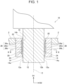
- the terminal connection structure includes a rod-shaped male terminal and a tube-shaped female terminal. Between the male terminal and the female terminal, a contact member that electrically connects the two terminals is provided. The contact member is disposed between an outer side surface of the male terminal and an inner side surface of the female terminal, and is configured to be capable of elastically deforming in the radial direction.
- the above terminal connection structure is used in a dynamic power circuit of an electrified vehicle, or the like.
- a relatively large electric current flows through the terminal connection structure.
- the amount of heat generation becomes large in the contact member that connects the two terminals.
- it is effective to increase the area of the contact of the contact member with the male terminal and the female terminal.
- the range of the elastic deformation of the contact member also increases when the male terminal is inserted into the female terminal.
- an insertion load that is, an insertion resistance
- the present disclosure provides a technology that makes it possible to increase the contact area of the contact member and to reduce the insertion load necessary for inserting the male terminal into the female terminal.
- a terminal connection structure in the present disclosure includes: a column-shaped male terminal that extends in an axial direction; a female terminal that demarcates a hole into which the male terminal is inserted; and at least one contact member that is sandwiched between an outer side surface of the male terminal and an inner side surface of the female terminal and that electrically connects the male terminal and the female terminal.
- the contact member includes a first contact portion and a second contact portion that are elastically deformed in a radial direction perpendicular to the axial direction, and the first contact portion and the second contact portion are provided at different positions from each other in the axial direction.
- the increase in the insertion load can be restrained even when the contact member is enlarged in the axial direction and the contact area of the contact member is increased. That is, when the male terminal is inserted into the female terminal, the first contact portion (or the second contact portion), first, elastically deforms, and thereafter, the second contact portion (or the first contact portion) elastically deforms. Thereby, a range of the contact member where the elastic deformations concurrently occur is relatively small, so that the increase in the insertion load is restrained.
- the first contact portion 26a extends from the upper end portion 22 to the intermediate portion 26m of the elastic piece 26 and the second contact portion 26b extends from the lower end portion 24 to the intermediate portion 26m of the elastic piece 26.
- a contact member 120 in Embodiment 2 includes an upper end portion 22, a lower end portion 24, and a plurality of elastic pieces 126 that extends between the upper end portion 22 and the lower end portion 24.
- Each of the plurality of elastic pieces 126 includes a first contact portion 26a, a second contact portion 126b, and an intermediate portion 26m that is positioned between the first contact portion 26a and the second contact portion 126b.
- the elastic deformation amount of the first contact portion 26a in the radial direction D2 is smaller than the elastic deformation amount of the second contact portion 126b in the radial direction D2.
- the protrusion amount X1 of the first contact portion 26a in the radial direction D2 is smaller than the protrusion amount X2 of the second contact portion 126b in the radial direction D2.
- the protrusion amount X1 of the first contact portion 26a is the protrusion amount with respect to the upper end portion 22 and the intermediate portion 26m
- the protrusion amount X2 of the second contact portion 126b is the protrusion amount with respect to the lower end portion 24 and the intermediate portion 26m.
- the first contact portion 26a and the second contact portion 126b are configured to have different elastic deformation amounts from each other, and in this respect, the contact member 120 in Embodiment 2 is different from the contact member 20 in Embodiment 1.
- the other configurations of the contact member 120 are the same as those in the terminal connection structure 10 in Embodiment 1.
- the first contact portion 26a is provided at a position that is closer to an opening (an insertion opening into which the male terminal 12 is inserted) of the hole 14h of the female terminal 14 than the second contact portion 126b is.
- the elastic deformation amount of the first contact portion 26a positioned on the insertion opening side of the hole 14h of the female terminal 14 can be relatively lessened, and the insertion load can be more effectively reduced.
- a contact member 220 in Embodiment 3 includes a plurality of first elastic pieces 26 and a plurality of second elastic pieces 226.
- the plurality of first elastic pieces 26 and the plurality of second elastic pieces 226 extend between the upper end portion 22 and the lower end portion 24.
- the plurality of first elastic pieces 26 can be configured similarly to the plurality of elastic pieces 26 in Embodiment 1, such that each first elastic piece 26 includes both of the first contact portion 26a and second contact portion 26b that elastically deforms in the radial direction D2.
- Each of the plurality of second elastic pieces 226 includes a third contact portion 226c.
- the first elastic piece 26 and the second elastic piece 226 are alternately arranged along the circumferential direction D3.
- the plurality of first elastic pieces 26 each of which includes both of the first contact portion 26a and the second contact portion 26b and the plurality of second elastic pieces 226 each of which includes the third contact portion 226c can be disposed evenly in the circumferential direction D3. Accordingly, the contact of the contact member 220 with the male terminal 12 and the female terminal 14 is stably maintained.
- the array order of the first elastic pieces 26 and the second elastic pieces 226 in the circumferential direction D3 is not limited to this, and can be freely designed.
- two or more first elastic pieces 26 adjacent to each other and two or more second elastic pieces 226 adjacent to each other may be alternately arranged along the circumferential direction D3.
- the first contact portion 26a extends from the upper end portion 22 to the intermediate portion 26m of the first elastic piece 26 and the second contact portion 26b extends from the lower end portion 24 to the intermediate portion 26m of the first elastic piece 26.
- the third contact portion 226c extends from the upper end portion 22 to the lower end portion 24. This configuration has an advantage in terms of the increase in the contact area of the contact member 220.
- the length of the first elastic piece 26 in the axial direction D1 and the length of the second elastic piece 226 in the axial direction D1 are equal to each other.
- the third contact portion 226c is larger in the dimension in the axial direction D1 than each of the first contact portion 26a and the second contact portion 26b. This configuration also has an advantage in terms of the increase in the contact area of the contact member 220.
- the contact member 220 in the embodiment is formed from a single plate member, by press working or the like. Accordingly, the thickness of the first elastic piece 26 and the thickness of the second elastic piece 226 are equal to each other. That is, the first contact portion 26a, the second contact portion 26b, and the third contact portion 226c are equal in thickness to each other.
- the elastic deformation amount of the third contact portion 226c in the radial direction D2 is larger than each of the elastic deformation amount of the first contact portion 26a in the radial direction D2 and the elastic deformation amount of the second contact portion 26b in the radial direction D2.
- a protrusion amount X3 of the third contact portion 226c in the radial direction D2 is larger than each of the protrusion amount X1 of the first contact portion 26a in the radial direction D2 and the protrusion amount X2 of the second contact portion 26b in the radial direction D2.
- the protrusion amount X1 of the first contact portion 26a is the protrusion amount of the first elastic piece 26 with respect to the upper end portion 22 and the intermediate portion 26m.
- the protrusion amount X2 of the second contact portion 26b is the protrusion amount of the first elastic piece 26 with respect to the lower end portion 24 and the intermediate portion 26m.
- the protrusion amount X3 of the third contact portion 226c is the protrusion amount of the second elastic piece 226 with respect to the upper end portion 22 and the lower end portion 24.
- the contact member 220 When the contact member 220 is disposed between the male terminal 12 and the female terminal 14 shown in FIG. 1 , the contact member 220 contacts with the inner side surface 14a of the female terminal 14, at the upper end portion 22, the lower end portion 24, and the intermediate portion 26m. Moreover, the contact member 220 contacts with the outer side surface 12a of the male terminal 12, at the first contact portion 26a, the second contact portion 26b, and the third contact portion 226c. In this configuration, the contact member 220 is stably held between the male terminal 12 and the female terminal 14.
- each terminal connection structure 10 disclosed in the present specification may be applied to only some of the plurality of terminal pairs 12, 14.
- the gap between the male terminal 12 and the female terminal 14 can be relatively lessened. Accordingly, even when the terminal connection structure 10 according to the present technology is applied to only at least one of the plurality of terminal pairs 12, 14, the positioning of the whole of the plurality of male terminals 12 can be performed with respect to the whole of the plurality of female terminals 14, with high accuracy.
- the vibration of the male terminal 12 with respect to the female terminal 14 is restrained, in all of the plurality of terminal pairs 12, 14.
- the male terminal 12 is a cylindrical member in the embodiments, but is not limited to this.
- the male terminal 12 may be a polygonal column-shaped member.
- the hole of the female terminal 14 is not limited to the configuration in the embodiments, and the female terminal 14 does not need to demarcate the hole 14h having a cylindrical section.
- the shape of the hole of the female terminal 14 can be appropriately altered in accordance with the shape of the male terminal 12.
Landscapes
- Coupling Device And Connection With Printed Circuit (AREA)
Applications Claiming Priority (1)
| Application Number | Priority Date | Filing Date | Title |
|---|---|---|---|
| JP2023220949A JP2025103511A (ja) | 2023-12-27 | 2023-12-27 | 端子接続構造 |
Publications (1)
| Publication Number | Publication Date |
|---|---|
| EP4579959A1 true EP4579959A1 (fr) | 2025-07-02 |
Family
ID=93743750
Family Applications (1)
| Application Number | Title | Priority Date | Filing Date |
|---|---|---|---|
| EP24217044.7A Pending EP4579959A1 (fr) | 2023-12-27 | 2024-12-03 | Structure de connexion de borne |
Country Status (5)
| Country | Link |
|---|---|
| US (1) | US20250219311A1 (fr) |
| EP (1) | EP4579959A1 (fr) |
| JP (1) | JP2025103511A (fr) |
| KR (1) | KR20250101853A (fr) |
| CN (1) | CN120222065A (fr) |
Citations (2)
| Publication number | Priority date | Publication date | Assignee | Title |
|---|---|---|---|---|
| JP2019008878A (ja) | 2017-06-20 | 2019-01-17 | 矢崎総業株式会社 | 端子接続構造 |
| US11139600B1 (en) * | 2020-06-23 | 2021-10-05 | TE Connectivity Services Gmbh | High performance contact element |
Family Cites Families (3)
| Publication number | Priority date | Publication date | Assignee | Title |
|---|---|---|---|---|
| CN102437454B (zh) * | 2011-08-31 | 2014-02-05 | 中航光电科技股份有限公司 | 双联冠簧及使用该冠簧的插孔 |
| JP5739827B2 (ja) * | 2012-03-12 | 2015-06-24 | 古河電気工業株式会社 | コネクタ端子用接触ばね、並びに、雌端子、雄端子、及び雌コネクタ |
| DE102013217256B3 (de) * | 2013-08-29 | 2015-03-05 | Robert Bosch Gmbh | Buchse sowie Hochstromsteckverbindung, die eine solche Buchse aufweist |
-
2023
- 2023-12-27 JP JP2023220949A patent/JP2025103511A/ja active Pending
-
2024
- 2024-11-28 KR KR1020240173436A patent/KR20250101853A/ko active Pending
- 2024-12-02 CN CN202411749536.3A patent/CN120222065A/zh active Pending
- 2024-12-03 EP EP24217044.7A patent/EP4579959A1/fr active Pending
- 2024-12-09 US US18/973,170 patent/US20250219311A1/en active Pending
Patent Citations (2)
| Publication number | Priority date | Publication date | Assignee | Title |
|---|---|---|---|---|
| JP2019008878A (ja) | 2017-06-20 | 2019-01-17 | 矢崎総業株式会社 | 端子接続構造 |
| US11139600B1 (en) * | 2020-06-23 | 2021-10-05 | TE Connectivity Services Gmbh | High performance contact element |
Also Published As
| Publication number | Publication date |
|---|---|
| US20250219311A1 (en) | 2025-07-03 |
| KR20250101853A (ko) | 2025-07-04 |
| JP2025103511A (ja) | 2025-07-09 |
| CN120222065A (zh) | 2025-06-27 |
Similar Documents
| Publication | Publication Date | Title |
|---|---|---|
| US11277047B2 (en) | Busbar apparatus, motor, and method of manufacturing busbar apparatus | |
| JP5335265B2 (ja) | 電動機 | |
| US10477717B2 (en) | Self-aligning busbar assembly | |
| US7795767B2 (en) | Motor with multiple bus rings | |
| US11189958B2 (en) | Connector that includes holding body with covering part | |
| JP6249991B2 (ja) | 配線モジュール | |
| US10636556B2 (en) | Bus bar unit and manufacturing method thereof | |
| JP2019032931A (ja) | 導体モジュール | |
| US11901792B2 (en) | Bus bar unit, stator, and motor | |
| WO2019102643A1 (fr) | Unité de barre omnibus et moteur | |
| CN116134681A (zh) | 连接器 | |
| EP4579959A1 (fr) | Structure de connexion de borne | |
| EP4557529A1 (fr) | Structure de connexion de borne | |
| WO2017204023A1 (fr) | Dispositif de conversion de puissance et procédé de fabrication associé | |
| US12341392B2 (en) | Connection ring terminal, connection ring, and motor | |
| JP6932219B1 (ja) | 電力変換装置 | |
| EP4580009A1 (fr) | Moteur | |
| US20250233472A1 (en) | Motor | |
| US12476442B2 (en) | Electrical connection box | |
| US20250038609A1 (en) | Armature and rotating electrical machine | |
| EP4303916A1 (fr) | Module à semi-conducteurs | |
| CN119864978A (zh) | 用于驱动车辆的电机 | |
| CN121128033A (zh) | 用于模块电极联接端的用于提供防触碰保护的壳体、模块电极联接端、连接组件和用于机动车的电池模块 | |
| WO2022138597A1 (fr) | Faisceau de câbles | |
| JP2007074879A (ja) | モータ用配電部材及びモータ用配電モジュール |
Legal Events
| Date | Code | Title | Description |
|---|---|---|---|
| PUAI | Public reference made under article 153(3) epc to a published international application that has entered the european phase |
Free format text: ORIGINAL CODE: 0009012 |
|
| STAA | Information on the status of an ep patent application or granted ep patent |
Free format text: STATUS: REQUEST FOR EXAMINATION WAS MADE |
|
| 17P | Request for examination filed |
Effective date: 20241203 |
|
| AK | Designated contracting states |
Kind code of ref document: A1 Designated state(s): AL AT BE BG CH CY CZ DE DK EE ES FI FR GB GR HR HU IE IS IT LI LT LU LV MC ME MK MT NL NO PL PT RO RS SE SI SK SM TR |