EP4579964A1 - Dispositif de contact de bande lumineuse avec dispositif de protection - Google Patents
Dispositif de contact de bande lumineuse avec dispositif de protection Download PDFInfo
- Publication number
- EP4579964A1 EP4579964A1 EP23220781.1A EP23220781A EP4579964A1 EP 4579964 A1 EP4579964 A1 EP 4579964A1 EP 23220781 A EP23220781 A EP 23220781A EP 4579964 A1 EP4579964 A1 EP 4579964A1
- Authority
- EP
- European Patent Office
- Prior art keywords
- contact
- arrangement
- unlocking
- plug
- section
- Prior art date
- Legal status (The legal status is an assumption and is not a legal conclusion. Google has not performed a legal analysis and makes no representation as to the accuracy of the status listed.)
- Pending
Links
Images



Classifications
-
- H—ELECTRICITY
- H01—ELECTRIC ELEMENTS
- H01R—ELECTRICALLY-CONDUCTIVE CONNECTIONS; STRUCTURAL ASSOCIATIONS OF A PLURALITY OF MUTUALLY-INSULATED ELECTRICAL CONNECTING ELEMENTS; COUPLING DEVICES; CURRENT COLLECTORS
- H01R25/00—Coupling parts adapted for simultaneous co-operation with two or more identical counterparts, e.g. for distributing energy to two or more circuits
- H01R25/14—Rails or bus-bars constructed so that the counterparts can be connected thereto at any point along their length
- H01R25/142—Their counterparts
-
- H—ELECTRICITY
- H01—ELECTRIC ELEMENTS
- H01R—ELECTRICALLY-CONDUCTIVE CONNECTIONS; STRUCTURAL ASSOCIATIONS OF A PLURALITY OF MUTUALLY-INSULATED ELECTRICAL CONNECTING ELEMENTS; COUPLING DEVICES; CURRENT COLLECTORS
- H01R13/00—Details of coupling devices of the kinds covered by groups H01R12/70 or H01R24/00 - H01R33/00
- H01R13/44—Means for preventing access to live contacts
- H01R13/447—Shutter or cover plate
- H01R13/453—Shutter or cover plate opened by engagement of counterpart
- H01R13/4534—Laterally sliding shutter
-
- H—ELECTRICITY
- H01—ELECTRIC ELEMENTS
- H01R—ELECTRICALLY-CONDUCTIVE CONNECTIONS; STRUCTURAL ASSOCIATIONS OF A PLURALITY OF MUTUALLY-INSULATED ELECTRICAL CONNECTING ELEMENTS; COUPLING DEVICES; CURRENT COLLECTORS
- H01R13/00—Details of coupling devices of the kinds covered by groups H01R12/70 or H01R24/00 - H01R33/00
- H01R13/44—Means for preventing access to live contacts
- H01R13/447—Shutter or cover plate
- H01R13/453—Shutter or cover plate opened by engagement of counterpart
- H01R13/4538—Covers sliding or withdrawing in the direction of engagement
-
- H—ELECTRICITY
- H01—ELECTRIC ELEMENTS
- H01R—ELECTRICALLY-CONDUCTIVE CONNECTIONS; STRUCTURAL ASSOCIATIONS OF A PLURALITY OF MUTUALLY-INSULATED ELECTRICAL CONNECTING ELEMENTS; COUPLING DEVICES; CURRENT COLLECTORS
- H01R13/00—Details of coupling devices of the kinds covered by groups H01R12/70 or H01R24/00 - H01R33/00
- H01R13/64—Means for preventing incorrect coupling
-
- F—MECHANICAL ENGINEERING; LIGHTING; HEATING; WEAPONS; BLASTING
- F21—LIGHTING
- F21V—FUNCTIONAL FEATURES OR DETAILS OF LIGHTING DEVICES OR SYSTEMS THEREOF; STRUCTURAL COMBINATIONS OF LIGHTING DEVICES WITH OTHER ARTICLES, NOT OTHERWISE PROVIDED FOR
- F21V21/00—Supporting, suspending, or attaching arrangements for lighting devices; Hand grips
- F21V21/34—Supporting elements displaceable along a guiding element
- F21V21/35—Supporting elements displaceable along a guiding element with direct electrical contact between the supporting element and electric conductors running along the guiding element
-
- F—MECHANICAL ENGINEERING; LIGHTING; HEATING; WEAPONS; BLASTING
- F21—LIGHTING
- F21V—FUNCTIONAL FEATURES OR DETAILS OF LIGHTING DEVICES OR SYSTEMS THEREOF; STRUCTURAL COMBINATIONS OF LIGHTING DEVICES WITH OTHER ARTICLES, NOT OTHERWISE PROVIDED FOR
- F21V23/00—Arrangement of electric circuit elements in or on lighting devices
- F21V23/06—Arrangement of electric circuit elements in or on lighting devices the elements being coupling devices, e.g. connectors
Definitions
- Generic systems and generic contact devices of such systems are designed to implement a generic luminaire that is elongated in a longitudinal direction and comprises a plurality of longitudinally elongated support rails.
- the support rails serve to fix the luminaire to a building structure, for example, to a ceiling.
- the support rails represent a type of basic framework for the luminaire and are designed to accommodate supply lines and preferably to accommodate mounting bodies to which lamps are attached.
- an infrastructure for the luminaire is provided via the support rails.
- Electrical functional elements of the luminaire are usually attached to the mounting bodies, for example lamps, in particular comprising circuit boards with LEDs, radio modules, electrical cables and/or operating devices.
- the respective support rail is usually first attached to the building structure and then the mounting body, which is equipped with at least one of the electrical functional elements of the luminaire, is fixed to the support rail, so that the support rail and the mounting body enclose an interior space in which essential elements of the luminaire are arranged, for example circuit boards, operating devices, contact devices, etc.
- the support rail and The mounting body is each elongated in a longitudinal direction; the longitudinal extent is preferably at least five times the extent perpendicular to the longitudinal direction.
- the support rail typically has a U-shaped cross-section perpendicular to the longitudinal direction, which extends in a vertical direction and in a transverse direction and is open at one vertical end and is formed by a support rail base and two support rail side walls.
- the support rail side walls thus run vertically away from the support rail base, and the support rail base connects the transversely spaced support rail side walls.
- the support rail base and the support rail side walls can have contours or recesses.
- the support rail base and the support rail side walls typically together form an interior space that is at least partially enclosed by the support rail side walls and the support rail base.
- the interior space is thus defined by the support rail.
- all support rails of a system have the features described here.
- a generic system often has at least a first and a second support rail, which are connected to one another at their mutually facing longitudinal ends to form the luminaire.
- the mounting body often has a cross-section perpendicular to the longitudinal direction, which comprises a mounting body base extending in the transverse direction and mounting body side walls extending vertically away from the mounting body base on the two transverse sides of the mounting base.
- the support rail and mounting body are usually manufactured separately from one another. Particularly preferably, the support rail and/or mounting body are each usually manufactured from a single sheet by forming.
- the mounting body is held in place by a retaining spring on the mounting rail anchors in the operating state of the system, in which the system is used as intended.
- the state of the art offers various possibilities for implementing a Such a retaining spring is known.
- a generic system comprises a current guide rail, which is usually made of plastic, in particular by means of an extrusion or injection molding process, and which is also elongated in the longitudinal direction, i.e., has an elongated longitudinal extension between its two longitudinal ends.
- the current guide rail is usually arranged on an inner side of the support rail facing the interior and is fixed to the support rail, in particular to the support rail base and/or to at least one of the support rail side walls.
- the current guide rail extends over a significant portion of the length of the support rail, in particular over at least 80% of the longitudinal extension of the support rail.
- the current guide rail typically has several channels arranged side by side along a row direction, which are open to an access side accessible from the interior.
- the current conducting rail is fixed to the support rail in such a way that the alignment direction runs perpendicular to the longitudinal direction.
- the alignment direction runs parallel to the transverse direction in the operating state of the system.
- the channels preferably extend continuously over the entire length of the current conducting rail.
- the transverse direction, the longitudinal direction and the vertical direction run perpendicular to one another.
- At least one conducting wire is arranged, in particular exactly one conducting wire or exactly two conducting wires, which in the respective channel are held at a distance from one another, and at at least one longitudinal end of the current conducting rail, the conducting wires are usually connected to an external voltage source, via which electrical energy and in particular electrical signals can be applied to the conducting wires.
- the conducting wires can thus serve as supply lines in the support rails.
- an electrical connector designed in particular as an electrical feed device, is usually arranged at the longitudinal end and is electrically connected to the conducting wires.
- an electrical connector is provided at each longitudinal end of the current conducting rail.
- the electrical connectors can, for example, be designed as mutually corresponding connectors, for example a first as a plug and a second as a socket.
- longitudinally adjacent current conducting rails can be electrically connected to one another, so that the conducting wires can form through-wiring.
- the system usually further comprises a contact device, via which an electrical contact is established between the conductor wires assigned to the conductor rail and at least one electrical functional element of the mounting body.
- the contact device is usually fixed to the mounting body and ensures an electrical connection of the at least one electrical functional element when the mounting body is held in the operating state of the system or in its intended position on the support rail in which the luminaire is realized.
- the contact device is designed to engage in the channels from the access side of the support rail in order to contact the conductor wires.
- the contact device has a plurality of contact units arranged next to one another in a direction of arrangement, wherein in the operating state of the system, each of the contact units is in electrically conductive contact with one of the conductor wires arranged in the channels of the conductor rail.
- the Arrangement direction which is defined with reference to the contact device, arranged parallel to the alignment direction, which is defined with reference to the current conducting rail.
- the contact device is arranged with its contact side on the access side of the current conducting rail, wherein the contact units for contacting the conductor wires are inserted into the channels along a plug-in direction resulting from the arrangement of the contact units and defined for the contact device, wherein the plug-in direction usually runs perpendicular to the arrangement direction and, accordingly, to realize the operating state, perpendicular to the alignment direction.
- Generic systems are used in a wide range of applications, for example in warehouses, production halls, supermarkets, or open-plan offices, where luminaires with a plurality of support rails and mounting bodies are used.
- the basic principle of luminaires manufactured with a generic system is that the support rails form the electrical and mechanical infrastructure of these luminaires, whereas the mounting bodies are attached to the support rails and contain the electrical functional elements required in the respective application area.
- the electrical functional elements are usually designed as lighting modules with light sources, in particular comprising LED boards.
- further electrical functional elements can also be provided on the respective mounting body, such as a presence sensor (e.g., an infrared sensor), a camera, a radio module, etc.
- the electrical functional elements are usually fixed to the mounting body.
- each luminaire component can comprise a support rail, a current conducting rail and a mounting body and in particular a coupling fastened to the support rail.
- the luminaire components are arranged one behind the other in the longitudinal direction, wherein the support rails of the respective luminaire components are mechanically connected to one another by means of the coupling and the supply lines that run in the support rails, in particular the lead wires arranged in the current conducting rails of the luminaire components, are electrically connected to one another in pairs, i.e. one lead wire of the first luminaire component is connected to one lead wire of the second luminaire component.
- a luminaire of the respective system thus comprises a plurality of support rails and in particular a plurality of mounting bodies and/or current guide rails or a plurality of luminaire components, which are each connected to one another as explained.
- the support rails are usually delivered with one longitudinal section of the coupling positioned in the respective support rail and another longitudinal section protruding from the support rail, with which it is then inserted into another support rail to secure the two support rails to each other.
- the contact devices are then arranged with their contact sides within the interior of the support rail on the access side of the current conducting rail so that the functional element connected to the respective contact device can be electrically connected to at least some of the conducting wires by means of the contact device.
- the contacting of the conducting wires by the contact device is often carried out in such a way that a mounting body with a contact device pre-mounted thereon is arranged at the open end of the support rail and the contact units of the contact device are inserted into the channels of the current conducting rail, while the contact device is fixed to the mounting body.
- a busbar of a generic system typically has a large number of channels arranged side by side in the direction of alignment, typically at least ten, preferably at least thirteen, ensuring correct contact between the conductor wires arranged in the channels is not easy. It must be taken into account that the busbar, with all its channels, usually extends in the direction of alignment over a limited area of extension, so that the busbar, and thus a luminaire manufactured using the system, does not have to have excessive dimensions.
- the busbar generally extends in the direction of alignment with its total length over less than 20 cm, in particular less than 15 cm.
- the channel walls that separate the clear cross-sections of two adjacent channels of the busbar generally have a channel wall thickness of less than 5 mm, in particular less than 4 mm, and in particular less than 3 mm.
- the contact device and its contact units must therefore be carefully aligned relative to the busbar so that their contact units fit into the channels provided for them. and in particular so that the contact units do not contact unwanted components at too early a point in time due to the contact device being positioned at an angle relative to the conductor rail.
- each of the conductor wires arranged in the channels of the conductor rail is usually assigned a specific function, for example the function as a data conductor, neutral conductor, phase conductor or PE conductor, so that correct positioning of the contact device relative to the conductor rail and correct contacting of the contact units on the conductor wires intended for them is necessary for the correct functioning of a luminaire and also for safety reasons.
- Various measures have already been taken in the prior art to design a contact device in such a way that incorrect contact is avoided wherever possible. For example, it is known to design the contact device on its outer contour corresponding to an inner contour of the support rail, so that the contact device can only be arranged in a desired position on the access side of the current conducting rail determined by the interaction of the contours.
- a contact device with a protective device which has a protective element which, in order to protect the contact units, covers them at least in sections and whose mobility along the plug-in direction is blocked in the rest position by a locking section of the protective device being in contact with a blocking section provided on the housing, wherein the protective device has a pivotable unlocking pawl and by pivoting the unlocking pawl the mobility can be released so that the contact device can be plugged onto a current conducting rail
- this principle has proven to be disadvantageous.
- Such a pivoting latch can be moved with little friction due to its rotatable bearing and can therefore be moved easily and reliably to enable the movement, such a latch does not, however, enable a sufficiently precise definition of a plug-in position in which only the contact device can be plugged onto the conductor rail to make contact with it, and this across the entire extent of a conductor rail. It must be taken into account that the distances between the channels and thus the conductor wires in a conductor rail are becoming increasingly smaller, so that a precise definition of a plug-in position is becoming increasingly important.
- the present invention is based on the object of providing a contact device for a system for producing a luminaire comprising a current conducting rail or such a system or a luminaire comprising the contact device or a method for realizing a luminaire, with which at least one disadvantage of generic contact devices or systems or luminaires or methods can be at least partially remedied.
- the invention proposes a contact device with the features according to claim 1.
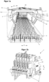
- the contact device is designed to be used as a contact device of a system as explained, which is designed to realize a longitudinally elongated luminaire, wherein the system has a mounting body elongated in a longitudinal direction, on which a lighting means is arranged as an electrical functional element, which is to be electrically supplied by means of the contact device.
- the contact device can also be provided for the electrical supply of other electrical functional elements that are arranged on further mounting bodies of the system.
- Such a system has a a longitudinally elongated support rail having an interior space in which a longitudinally elongated current conducting rail is arranged, which has channels arranged side by side in an array direction perpendicular to the longitudinal direction, are longitudinally elongated, and are open on an access side of the current conducting rail, in each of which at least one longitudinally elongated conductor wire is arranged.
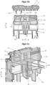
- the contact device is thus fundamentally designed to be used in such a system, for which purpose the contact device has a housing in which a plurality of contact units arranged side by side in an arrangement direction are arranged. The arrangement direction is defined with respect to the contact device or the housing of the contact device.
- each of the contact blades has an extension length of at least 5 mm, in particular an extension length of at least 7 mm, in particular an extension length of at least 10 mm, along a plug-in direction along which the contact units or their contact blades are to be introduced into the channels of the current conducting rail in order to contact the conductor wires.
- the contact device has a contact side and is designed to Contact side on the access side of the current conducting rail, which is defined by its explained properties, to be arranged by introducing at least some of its contact units along a plug-in direction into one of the channels in each case, contacting the conductor wires arranged in these channels.
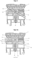
- the unlocking element is thus specifically mounted on the housing so that it can move freely, such that pressing on the unlocking arrangement along the plug-in direction causes the unlocking element to move relative to the housing perpendicular to the plug-in direction.
- the inclined position of the inclined surface section forces the unlocking element to move in the linear guide counter to the spring direction, thereby achieving the release position.
- the inclined surface section thus acts like a wedge-type friction device, generating a reversal of movement. Due to the inclined orientation of the inclined surface section, a pressing force exerted on the inclined surface section along the plug-in direction is converted into a displacement force counter to the spring direction.
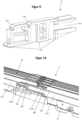
- each of the coding sections has at least one interruption along the longitudinal direction, wherein the interruptions of the coding sections are offset from one another in the longitudinal direction.
- the contact device can be arranged along the entire longitudinal extent of the coding arrangement on the access side of the current conducting rail, with its contact units being inserted into the channels. Despite the interruption provided in the respective coding section, the contact device can thus be arranged at any longitudinal position relative to the current conducting rail along the coding arrangement, i.e., along the extent of the coding sections, with its contact side on the access side, while reaching the release position. starting from the rest position.
- the coding arrangement preferably extends uninterruptedly over at least 90%, in particular at least 95%, of the total length of the conductor rail.
- the corresponding spaced-apart arrangements of the unlocking sections or the rigid coupling of the unlocking sections can be particularly advantageous for the functionality of the protective device; in particular, it can be particularly reliably ensured that pressing against only one optionally selectable of the two unlocking sections has the same effect as pressing against both unlocking sections, wherein the effect relates to reaching the release position starting from the rest position.
- the unlocking element is fixed in position relative to the protective element at least with a fixing section along the plug-in direction.
- the unlocking element can be guided particularly reliably to the protective element in such a way that the release position can be achieved by the unlocking element upon actuation of the unlocking arrangement or pressing against the unlocking arrangement along the plug-in direction, starting from the rest position.
- the unlocking element has an extension length in the arrangement direction that is a multiple, in particular at least three times, in particular at least four times, in particular at least five times, of an extension length of the unlocking element in a direction running perpendicular to the arrangement direction, in particular perpendicular to the arrangement direction and plug-in direction.
- the housing, the protective element, and the release element are each formed as a separately manufactured injection-molded component. This allows each of these injection-molded components to be specifically adapted to the requirements placed on it.
- the contact device comprises a first group of contact units and a second group of contact units spaced apart from the first group by a distance region in a direction perpendicular to the arrangement direction and perpendicular to the plug-in direction, wherein the protective device is arranged in the distance region between the two groups of contact units.
- the spaced-apart arrangement of the two groups of contact units can be particularly advantageous for arranging the contact units at a small distance from one another, relative to the arrangement direction, and at the same time ensuring good accessibility of the contact units for connecting an electrical functional element.
- All contact units are arranged next to one another or lined up one behind the other along the arrangement direction, wherein the contact units of the different groups are arranged offset from one another in the aforementioned direction.
- the protective element has a guide section for each individual contact unit assigned to this respective contact unit, which guides a contact blade of the respective contact unit laterally both in the rest position and in the release position, as well as during a movement of the protective element along the insertion direction starting from the release position.
- the guide section is preferably arranged on both sides of the contact blade, with the term " sides” referring to the two sides relative to the arrangement direction.
- the movement of the protective element starting from the release position along the insertion direction refers to a movement of the protective element that the protective element performs when the contact device is arranged with its contact side on the access side of the current conducting rail and its contact units are inserted into the channels along the insertion direction.
- the distance along the insertion direction over which the contact blades of the contact units protrude beyond the protective element on the contact side along the insertion direction is thus increased so that they can be inserted into the channels of the current conducting rail.
- the contact blades can be aligned particularly reliably so that they can be inserted smoothly into the channels of the current conducting rail.
- the contact units preferably each have a contact blade made of a conductive material, in particular metal. Such contact blades must have a certain length so that they can contact the conductor wires arranged in the channels.
- a contact blade preferably has a length along the extension direction that is at least ten times, in particular at least twenty times, in particular at least thirty times the contact blade thickness, i.e. the extension length of the contact blade in the arrangement direction.
- the guide section extends on both sides of the contact blade over the same longitudinal extension section as the contact blade.
- the longitudinal extension section refers to a length section along a direction that is perpendicular to the plug-in direction and perpendicular to the arrangement direction.
- the longitudinal extension length of the longitudinal extension section preferably increases starting from the release position during the movement of the protective element along the plug-in direction.
- the guide section and contact blade overlap along the aforementioned direction over a length that increases during the movement of the protective element, which the protective element, as explained above, carries out starting from the release position along the plug-in direction when the contact blades are introduced into the channels of the current-conducting rail along the plug-in direction or when the contact blades increasingly extend beyond the protective element along the plug-in direction.
- the guide section is funnel-shaped, with a free space provided for the contact blade tapering along the plug-in direction towards the contact side. This ensures improved guidance towards the contact side, i.e. guidance with less play the closer the guide is to the contact side.
- the guide section encloses the contact blade in the manner of a U-shape and is thus open at one end.
- the U-shape preferably describes the cross-section of the guide section perpendicular to the plug-in direction. This allows both a sufficient Flexibility must be guaranteed as well as sufficient guidance of the contact blade.
- a first group of contact units is arranged on a first side of the protective element, which are arranged next to one another in the arrangement direction, and a second group of contact units is arranged on a second side of the protective element, which are arranged next to one another in the arrangement direction.
- a first group of guide sections is provided on the first side, each of which guides the contact blade of one of the contact units of the first group, and a second group of guide sections is provided on the second side, each of which guides the contact blade of one of the contact units of the second group.
- the two groups of contact units can be the two groups of contact units explained above.
- all contact units i.e., both those of the first and those of the second group
- the protective element is preferably arranged between the two groups of contact units in a direction perpendicular to the plug-in direction and perpendicular to the arrangement direction, which in the case of intended use thus runs along the longitudinal direction, so that the sides of the protective element relate to this direction and thus point away from each other along this direction.
- the guide sections extend in the plug-in direction over at least 1%, in particular at least 3%, in particular at least 5% of a total extension length of the contact device, which the contact device in its rest position in the plug-in direction. In one embodiment, the guide sections extend in the plug-in direction over less than 50%, in particular less than 30%, in particular less than 20% of the total extension length of the contact device which it has in its rest position in the plug-in direction. In one embodiment, the guide sections extend in the plug-in direction over at least 5%, in particular at least 10% of a total extension length of the protective element which the protective element has in the plug-in direction. In one embodiment, the guide sections extend in the plug-in direction over less than 70%, in particular less than 50%, in particular less than 30% of the total extension length of the protective element which the protective element has in the plug-in direction.
- the unlocking element is arranged at least predominantly, in particular entirely, within the protective element. In one embodiment, the unlocking element extends over at least 50%, in particular at least 70%, of a total extension length that the protective element has along the arrangement direction. In one embodiment, the unlocking element extends over at least 50%, in particular at least 70%, of a total extension length that the contact device has along the arrangement direction.
- the housing has a sliding guide for the unlocking element, which extends along the plugging direction and in which the unlocking element is mounted and guided during a movement along the plugging direction relative to the housing, starting from the release position, perpendicular to the plugging direction.
- This sliding guide is preferably a linear guide.
- the unlocking element preferably has at least one guide section which is assigned to a sliding guide section of the sliding guide, wherein in the rest position the guide section is arranged offset perpendicular to the plugging direction with respect to the sliding guide section assigned to it, and in the release position is arranged in alignment with the sliding guide section assigned to it.
- the guide section is only guided along the plug-in direction by the sliding guide section when the release position is reached, whereas in the rest position such guidance is not possible due to the offset.
- the guide section preferably forms at least part of the locking section of the contact device.
- the unlocking element preferably has at least two guide sections which are spaced apart from one another perpendicular to the plug-in direction, in particular along the arrangement direction, and which are each assigned to one of two sliding guide sections of the sliding guide, which are also spaced apart from one another perpendicular to the plug-in direction, in particular along the arrangement direction.
- the protective element starting from the release position, can only be moved along the plug-in direction relative to the housing together with the unlocking element.
- the protective element and the unlocking element each have guide sections by means of which they are each guided on the housing during a movement along the plug-in direction relative to the housing.
- the movement along the plug-in direction can be the movement that the protective element executes together with the unlocking element when the contact units are arranged in the channels of the current guide rail.
- the protective element has a guide section that, during the movement, is guided in the same sliding guide section of the housing in which a guide section of the unlocking element is also guided.
- the cross sections of the guide sections of the unlocking element and protective element are each adapted to the cross section of the sliding guide section, so that the two guide sections are guided in the same way by the sliding guide section.
Landscapes
- Details Of Connecting Devices For Male And Female Coupling (AREA)
Priority Applications (1)
| Application Number | Priority Date | Filing Date | Title |
|---|---|---|---|
| EP23220781.1A EP4579964A1 (fr) | 2023-12-29 | 2023-12-29 | Dispositif de contact de bande lumineuse avec dispositif de protection |
Applications Claiming Priority (1)
| Application Number | Priority Date | Filing Date | Title |
|---|---|---|---|
| EP23220781.1A EP4579964A1 (fr) | 2023-12-29 | 2023-12-29 | Dispositif de contact de bande lumineuse avec dispositif de protection |
Publications (1)
| Publication Number | Publication Date |
|---|---|
| EP4579964A1 true EP4579964A1 (fr) | 2025-07-02 |
Family
ID=89428576
Family Applications (1)
| Application Number | Title | Priority Date | Filing Date |
|---|---|---|---|
| EP23220781.1A Pending EP4579964A1 (fr) | 2023-12-29 | 2023-12-29 | Dispositif de contact de bande lumineuse avec dispositif de protection |
Country Status (1)
| Country | Link |
|---|---|
| EP (1) | EP4579964A1 (fr) |
Citations (3)
| Publication number | Priority date | Publication date | Assignee | Title |
|---|---|---|---|---|
| DE102008032192B3 (de) | 2008-07-09 | 2010-01-21 | Wago Verwaltungsgesellschaft Mbh | Steckverbinder |
| DE102011001274A1 (de) * | 2011-03-15 | 2012-09-20 | Phoenix Contact Gmbh & Co. Kg | Stecksystem mit einem Hutschienenbus |
| DE102021106844A1 (de) * | 2021-03-19 | 2022-09-22 | Trilux Gmbh & Co. Kg | System und Kontakteinrichtung mit Fehlsteckschutz |
-
2023
- 2023-12-29 EP EP23220781.1A patent/EP4579964A1/fr active Pending
Patent Citations (3)
| Publication number | Priority date | Publication date | Assignee | Title |
|---|---|---|---|---|
| DE102008032192B3 (de) | 2008-07-09 | 2010-01-21 | Wago Verwaltungsgesellschaft Mbh | Steckverbinder |
| DE102011001274A1 (de) * | 2011-03-15 | 2012-09-20 | Phoenix Contact Gmbh & Co. Kg | Stecksystem mit einem Hutschienenbus |
| DE102021106844A1 (de) * | 2021-03-19 | 2022-09-22 | Trilux Gmbh & Co. Kg | System und Kontakteinrichtung mit Fehlsteckschutz |
Similar Documents
| Publication | Publication Date | Title |
|---|---|---|
| EP4413296B1 (fr) | Bande lumineuse modulaire dotée d'un dispositif de pré-centrage | |
| EP3644460B1 (fr) | Système de rails conducteurs | |
| EP4678976A2 (fr) | Luminaire avec connecteur détachable | |
| DE102022106587A1 (de) | System und Kontakteinrichtung mit Fehlsteckschutz | |
| DE102022112197A1 (de) | Modulares Lichtband mit Vorzentrierungseinrichtung | |
| EP4002615A1 (fr) | Fixation d'un couplage pour un système de bande lumineuse | |
| DE102018106234A1 (de) | Längenausgleichsvorrichtung für Stromführungssysteme | |
| DE102021106844A1 (de) | System und Kontakteinrichtung mit Fehlsteckschutz | |
| EP1518298B1 (fr) | Dispositif de derivation pour ligne electrique | |
| DE102018106235A1 (de) | Längenausgleichsvorrichtung für Stromführungssysteme | |
| DE102023136878A1 (de) | Lichtband-Kontakteinrichtung mit Schutzvorrichtung | |
| EP4122058B1 (fr) | Bande lumineuse à éléments d'éclairage connectés | |
| WO2025140910A1 (fr) | Dispositif de contact protégé pour une bande lumineuse | |
| DE102023136879A1 (de) | Stromleitschiene eines Lichtbands | |
| DE102021133713A1 (de) | Modulare Leuchte mit Kontakteinrichtung | |
| DE102020133152A1 (de) | Langgestreckte Leuchte mit korrespondierender Kontakteinrichtung | |
| DE102024106074A1 (de) | Modulare langgestreckte Leuchte | |
| DE102018131996B4 (de) | Leuchte und zu deren Realisierung vorgesehenes System und Verfahren | |
| EP4361499A2 (fr) | Bande lumineuse dotée de composants optimisés pour le démontage | |
| WO2025181285A1 (fr) | Luminaire modulaire allongé | |
| EP4646553A1 (fr) | Bande lumineuse ayant un composant indirect | |
| WO2025181084A1 (fr) | Bande lumineuse à composants positionnés de manière optimisée | |
| DE102024106072A1 (de) | Montageoptimiertes System zur Realisierung eines Lichtbands | |
| DE102024106070A1 (de) | Langlebiges Lichtband | |
| DE102022126024A1 (de) | Lichtband mit demontageoptimierten Komponenten |
Legal Events
| Date | Code | Title | Description |
|---|---|---|---|
| PUAI | Public reference made under article 153(3) epc to a published international application that has entered the european phase |
Free format text: ORIGINAL CODE: 0009012 |
|
| STAA | Information on the status of an ep patent application or granted ep patent |
Free format text: STATUS: REQUEST FOR EXAMINATION WAS MADE |
|
| 17P | Request for examination filed |
Effective date: 20241220 |
|
| AK | Designated contracting states |
Kind code of ref document: A1 Designated state(s): AL AT BE BG CH CY CZ DE DK EE ES FI FR GB GR HR HU IE IS IT LI LT LU LV MC ME MK MT NL NO PL PT RO RS SE SI SK SM TR |
|
| GRAP | Despatch of communication of intention to grant a patent |
Free format text: ORIGINAL CODE: EPIDOSNIGR1 |
|
| STAA | Information on the status of an ep patent application or granted ep patent |
Free format text: STATUS: GRANT OF PATENT IS INTENDED |
|
| RIC1 | Information provided on ipc code assigned before grant |
Ipc: H01R 25/14 20060101AFI20260129BHEP Ipc: F21V 21/35 20060101ALI20260129BHEP Ipc: F21V 23/06 20060101ALI20260129BHEP Ipc: H01R 13/453 20060101ALI20260129BHEP Ipc: H01R 13/64 20060101ALI20260129BHEP |
|
| INTG | Intention to grant announced |
Effective date: 20260303 |