EP4579979A1 - Procédé d'injection de puissance électrique dans un réseau d'alimentation électrique au moyen d'une éolienne - Google Patents
Procédé d'injection de puissance électrique dans un réseau d'alimentation électrique au moyen d'une éolienne Download PDFInfo
- Publication number
- EP4579979A1 EP4579979A1 EP23220516.1A EP23220516A EP4579979A1 EP 4579979 A1 EP4579979 A1 EP 4579979A1 EP 23220516 A EP23220516 A EP 23220516A EP 4579979 A1 EP4579979 A1 EP 4579979A1
- Authority
- EP
- European Patent Office
- Prior art keywords
- frequency
- power
- filter
- low
- weighting factor
- Prior art date
- Legal status (The legal status is an assumption and is not a legal conclusion. Google has not performed a legal analysis and makes no representation as to the accuracy of the status listed.)
- Pending
Links
Images




Classifications
-
- H—ELECTRICITY
- H02—GENERATION; CONVERSION OR DISTRIBUTION OF ELECTRIC POWER
- H02J—ELECTRIC POWER NETWORKS; CIRCUIT ARRANGEMENTS OR SYSTEMS FOR SUPPLYING OR DISTRIBUTING ELECTRIC POWER; SYSTEMS FOR STORING ELECTRIC ENERGY
- H02J3/00—Circuit arrangements for AC mains or AC distribution networks
- H02J3/38—Arrangements for feeding a single network from two or more generators or sources in parallel; Arrangements for feeding already energised networks from additional generators or sources in parallel
- H02J3/40—Synchronisation of generators for connection to a network or to another generator
-
- H—ELECTRICITY
- H02—GENERATION; CONVERSION OR DISTRIBUTION OF ELECTRIC POWER
- H02J—ELECTRIC POWER NETWORKS; CIRCUIT ARRANGEMENTS OR SYSTEMS FOR SUPPLYING OR DISTRIBUTING ELECTRIC POWER; SYSTEMS FOR STORING ELECTRIC ENERGY
- H02J3/00—Circuit arrangements for AC mains or AC distribution networks
- H02J3/001—Arrangements for handling faults or abnormalities, e.g. emergencies or contingencies
- H02J3/0014—Arrangements for handling faults or abnormalities, e.g. emergencies or contingencies for preventing or reducing power oscillations in networks
- H02J3/00142—Oscillations concerning frequency
-
- F—MECHANICAL ENGINEERING; LIGHTING; HEATING; WEAPONS; BLASTING
- F03—MACHINES OR ENGINES FOR LIQUIDS; WIND, SPRING, OR WEIGHT MOTORS; PRODUCING MECHANICAL POWER OR A REACTIVE PROPULSIVE THRUST, NOT OTHERWISE PROVIDED FOR
- F03D—WIND MOTORS
- F03D7/00—Controlling wind motors
- F03D7/02—Controlling wind motors the wind motors having rotation axis substantially parallel to the air flow entering the rotor
- F03D7/04—Automatic control; Regulation
- F03D7/042—Automatic control; Regulation by means of an electrical or electronic controller
- F03D7/048—Automatic control; Regulation by means of an electrical or electronic controller controlling wind farms
-
- H—ELECTRICITY
- H02—GENERATION; CONVERSION OR DISTRIBUTION OF ELECTRIC POWER
- H02J—ELECTRIC POWER NETWORKS; CIRCUIT ARRANGEMENTS OR SYSTEMS FOR SUPPLYING OR DISTRIBUTING ELECTRIC POWER; SYSTEMS FOR STORING ELECTRIC ENERGY
- H02J3/00—Circuit arrangements for AC mains or AC distribution networks
- H02J3/001—Arrangements for handling faults or abnormalities, e.g. emergencies or contingencies
-
- H—ELECTRICITY
- H02—GENERATION; CONVERSION OR DISTRIBUTION OF ELECTRIC POWER
- H02J—ELECTRIC POWER NETWORKS; CIRCUIT ARRANGEMENTS OR SYSTEMS FOR SUPPLYING OR DISTRIBUTING ELECTRIC POWER; SYSTEMS FOR STORING ELECTRIC ENERGY
- H02J3/00—Circuit arrangements for AC mains or AC distribution networks
- H02J3/38—Arrangements for feeding a single network from two or more generators or sources in parallel; Arrangements for feeding already energised networks from additional generators or sources in parallel
- H02J3/381—Dispersed generators
-
- F—MECHANICAL ENGINEERING; LIGHTING; HEATING; WEAPONS; BLASTING
- F03—MACHINES OR ENGINES FOR LIQUIDS; WIND, SPRING, OR WEIGHT MOTORS; PRODUCING MECHANICAL POWER OR A REACTIVE PROPULSIVE THRUST, NOT OTHERWISE PROVIDED FOR
- F03D—WIND MOTORS
- F03D7/00—Controlling wind motors
- F03D7/02—Controlling wind motors the wind motors having rotation axis substantially parallel to the air flow entering the rotor
- F03D7/028—Controlling wind motors the wind motors having rotation axis substantially parallel to the air flow entering the rotor controlling wind motor output power
- F03D7/0284—Controlling wind motors the wind motors having rotation axis substantially parallel to the air flow entering the rotor controlling wind motor output power in relation to the state of the electric grid
-
- H—ELECTRICITY
- H02—GENERATION; CONVERSION OR DISTRIBUTION OF ELECTRIC POWER
- H02J—ELECTRIC POWER NETWORKS; CIRCUIT ARRANGEMENTS OR SYSTEMS FOR SUPPLYING OR DISTRIBUTING ELECTRIC POWER; SYSTEMS FOR STORING ELECTRIC ENERGY
- H02J2101/00—Supply or distribution of decentralised, dispersed or local electric power generation
- H02J2101/20—Dispersed power generation using renewable energy sources
- H02J2101/28—Wind energy
Definitions
- the present invention relates to a method for feeding electrical power into an electrical supply grid by means of a feed-in unit, in particular by means of a wind turbine or a wind farm.
- the invention also relates to a corresponding feed-in unit, in particular a corresponding wind turbine or a corresponding wind farm.
- Wind turbines are well known for generating electrical power from wind and feeding it into the electrical grid. In addition to providing energy, wind turbines often also serve to support the grid. At the very least, wind turbines should operate in a grid-supporting manner as much as possible.
- converter-based feed-in technologies also known as Type 2 systems, which operate in a grid-following or grid-supporting manner
- the contribution to frequency stability is achieved by first determining the frequency and, based on this, determining an active power setpoint using a controller and a P(f) characteristic.
- This active power setpoint is then passed on to and implemented by an active power control system of the wind turbine, which acts as an actuator.
- the active power setpoint may be calculated in a central wind farm control unit, which has a delay in determining the frequency because it uses, for example, a discrete Fourier transform (DFT).
- the controller that determines the active power setpoint from the frequency may also have dynamics.
- the communication between the central wind farm control unit and the wind turbine, to which the active power setpoint is transmitted, may involve a delay. Further delays can occur at the wind turbine, firstly due to a delayed reception of the signal transmitted by the central wind farm control unit and secondly due to the dynamics of the active power control.
- existing feeders especially wind turbines, may have no or no significant damping behavior for such frequency-dependent active power feed-in.
- a low-pass filter can be provided to filter out a frequency change before an active power setpoint is specified depending on the frequency and thus a changed frequency.
- a low-pass filter may be undesirable in the event of a grid fault, as it can lead to excessive delay.
- the present invention is therefore based on the object of addressing at least one of the above-mentioned problems.
- a solution is to be proposed in which, when specifying a frequency-dependent active power for feeding into the electrical supply grid, vibration excitation is avoided even in weakly damped electrical supply grids, while simultaneously enabling a rapid response to a frequency event, especially to a grid fault.
- an alternative to previously known solutions is to be proposed.
- a method according to claim 1 is proposed.
- Such a method thus relates to the feeding of electrical power into an electrical supply network having a mains voltage with a mains frequency.
- the feeding takes place by means of a feed-in unit, in particular by means of a wind turbine or a wind farm.
- the mains frequency is detected and transmitted as a frequency measurement signal.
- the frequency measurement signal is filtered into a frequency filter signal by means of a filter device with low-pass behavior, and a frequency-dependent power setpoint component is determined depending on this frequency filter signal.
- both filter functions filter the frequency measurement signal and can each output a filtered measurement signal that has been filtered differently. This not only results in two differently filtered frequency signals, but also in two different delays. Simply put, the filtered frequency signal filtered with the filter function with a larger low-pass time constant is more delayed, i.e., slower, than the other filtered frequency signal.
- one weighting factor can have the value 0 and the other the value 1. In this case, only one of the two filtered frequency signals is transmitted. However, these two weighting factors can change their value; in the other extreme case, the first weighting factor is 1 and the second is 0. In this case, the second filtered frequency signal is transmitted instead of the first.
- weighting factors allow both filtered frequency signals to be combined.
- Such behavior can also fulfill a grid regulation that requires a quick response in the event of a grid fault.
- weighting factors are provided, one for each filter function. However, it may be sufficient to use a single weighting factor if this weighting factor is applied directly to one filter function and applied to the other filter function by first subtracting it from 1.
- the first and second filter functions operate in parallel, are weighted with the first and second weighting factors, respectively, and can be switched between by changing the weighting factors.
- This aspect thus implements the principle described above.
- the two weighting factors can thus be used to implement the basic setting of a fast low-pass filter or a fast low-pass filter function.
- This fast low-pass filter can therefore be permanently deployed.
- the filter function can be switched to the other by adjusting the weighting factors, specifically by lowering one from 1 to 0 and raising the other from 0 to 1. Later, once the network has settled down, the filter function can be switched back by setting one weighting factor back to 1 and the other to 0.
- a simulation circuit will be set up in which the grid is formed by a phase shifter and a variable load.
- the phase shifter can be designed, in particular, as a synchronous machine operating at idle. Current and voltage are then recorded and further used in the central wind farm control unit. In particular, the frequency is determined from this, and a frequency-dependent target power value is determined and passed to a wind turbine, which accordingly has a power output that feeds into this test grid.
- the entire test setup can therefore be made up of the central wind farm control unit and the wind turbine, which is connected to and feeds into the test grid, plus the aforementioned variable load and the aforementioned phase shifter.
- the safety time can range from 1 min to 10 min.
- the frequency-dependent determination of the wind farm's power output was essentially viewed more as a control process.
- Particularly small time constants were advantageous for this purpose, so that an input variable of such an assumed control, in this case the grid frequency, could influence the wind farm's power output to be determined as quickly as possible.
- the feed unit thus achieves the advantages as explained above for the method and can also be specified accordingly.
- the feed-in unit be characterized by the provision of a central control unit. If the feed-in unit is a wind farm, in particular, a central farm control unit is provided. The method explained above can be carried out according to at least one aspect on such a central control unit or central farm control unit.
- the feed-in unit be prepared to execute a method according to one of the aspects described above.
- the method can be implemented in particular on the central control unit or central park control unit, which are thus preferably prepared to execute the method.
- the feed-in unit is designed as a wind farm, which is controlled by a cascade controller with three control loops.
- the proposed filter device and the proposed choice of the second low-pass time constant can be used to ensure that it operates slowly enough, depending on demand, to network fault or a critical time period after it, to make the cascade controller correspondingly stable, but otherwise to make the cascade controller correspondingly fast.
- FIG. 1 shows a schematic representation of a wind turbine according to the invention.
- the wind turbine 100 has a tower 102 and a nacelle 104 on the tower 102.
- An aerodynamic rotor 106 with three rotor blades 108 and a spinner 110 is provided on the nacelle 104.
- the aerodynamic rotor 106 is The wind turbine is set into rotation by the wind and thus also rotates an electrodynamic rotor or rotor of a generator, which is directly or indirectly coupled to the aerodynamic rotor 106.
- the electric generator is arranged in the nacelle 104 and generates electrical energy.
- the pitch angles of the rotor blades 108 can be changed by pitch motors at the rotor blade roots 109 of the respective rotor blades 108.
- the wind turbine 100 has an electrical generator 101, which is indicated in the nacelle 104. Electrical power can be generated by means of the generator 101.
- a feed-in unit 105 is provided, which can be designed particularly as an inverter. This can generate a three-phase feed-in current and/or a three-phase feed-in voltage according to amplitude, frequency, and phase for feeding into a grid connection point PCC. This can be done directly or jointly with other wind turbines in a wind farm.
- a system controller 103 is provided to control the wind turbine 100 and the feed-in unit 105. The system controller 103 can also receive default values from external sources, in particular from a central farm control unit.
- a target plant power P AS is determined based on the frequency thus recorded. This depends on the frequency and can also depend on the total power fed into the farm, which can also be referred to as the farm power. Specifically, a target farm power is first determined based on the frequency and compared with the actual farm power, and the target plant power P AS is adjusted accordingly. All of this can also include dynamics and thus a delay.
- an actual power P AI is then fed in and output according to the target power P AS .
- This conversion also includes dynamics, including dynamics for receiving the target values and dynamics for converting the target values into actual values, i.e., the actual output power.
- the electrical supply grid reacts to this and can change its grid voltage U Ne .
- This change can include a frequency change, which in turn is detected in the central park control unit 302.
- the simulation setup 500 can be used according to Figure 5 This includes a central park control unit 302 and a wind turbine 304, which can be representative of several wind turbines or all wind turbines of a wind farm.
- the reference numerals for this are as in the Figures 3 and 4 chosen because the elements can be the same or at least similar.
- a simplified arrangement is selected as the electrical supply network 506, comprising a variable load 508 and a phase shifter 510.
- the phase shifter 510 which can in particular essentially refer to a synchronous machine in no-load operation, essentially specifies the mains voltage U Ne at the mains frequency, but itself has no damping. If a small synchronous machine is selected as the phase shifter, changes in the fed-in power have a correspondingly greater effect on the behavior of this synchronous machine, and oscillations can occur particularly easily, since at least the phase shifter 510, i.e. the synchronous machine itself, has no or no significant damping. This makes it possible to test whether a sufficient internal damping in the simplified control system 300, which is Figure 5 also finds again, is given.
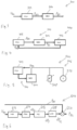
- FIG. 6 shows a schematic and simplified representation of a power control circuit 600.
- This circuit has a frequency detection block 612, which determines a frequency or frequency deviation df from the detected mains voltage U Ne .
- the frequency deviation df is a deviation from a nominal mains frequency.
- This frequency deviation df is fed into the low-pass filter block 614, resulting in a frequency filter signal df F.
- This signal is converted into a frequency-dependent nominal power component dPs in the power control block 616. This can be done using a droop, in which a power value is assigned to each frequency deviation from the nominal frequency.
- This frequency-dependent nominal power component dPs can be limited in the limiting block 618.
- the result is then a limited target power component dP SL .
- a basic target power component P 0S can be added to this limited target power component dP SL , namely in the summing point 620.
- the result is then a parking target power P PS .
- This parking target power can then be further processed, which is still related to Figure 9 It is particularly important that this parking target power P PS is compared with an actual parking power is compared to determine the plant's target power P AS .
- the park's target power P PS can be converted into a percentage value if the plant's target power P AS is desired as a percentage value.
- Such a power control structure 600 thus has some dynamic elements, including the low-pass filter block 614. This can be adjusted to try to achieve a desired speed and also a desired stability.
- FIG. 7 This power control structure 700 is based on the power control structure 600 of Figure 6 Except for the changes explained below, these two power control structures 600 and 700 may be the same and therefore the same reference numerals are used for the same or similar elements in Figure 7 as in Figure 6 used.
- the filter device 714 has a first and a second filter function 721 and 722. Both filter functions 721 and 722 are each designed as low-pass filters.
- the first filter function has a smaller time constant than the second filter function 722.
- the first filter function outputs a first partial filter frequency signal df F1
- the second filter function 722 outputs a second partial filter frequency signal df F2 .
- An average is then determined from the outputs of this previous step, i.e., the parallel filtering.
- the outputs are weighted by different factors, namely the weighting factors W1 and W2, and with more filters, correspondingly more weighting factors. If both weighting factors are set to 0.5 in the example shown, summing point 726 will output an arithmetic mean.
- the interval between the times t 1 and t 2 can be in the range of 0.1 s to 30 s, in particular 1 s to 10 s.
- the time ts can, for example, be 1 to 10 s after time t2 , but also up to 1 min or even up to 5 min. It is possible that the network is observed and as long as a certain oscillation amplitude is still recorded, nor is it assumed that the network is not completely stable or at least not yet fully recovered.
- the first weighting factor W1 can be ramped up from 0 to 1 from time ts to time t4
- the second weighting factor W2 can be ramped down from 1 to 0 from time ts to time t4 .
- the first weighting factor has reached the value 1 and the second weighting factor has reached the value 0. From time t4 , stable operation can be assumed again.
- FIG 9 schematically shows a cascade control structure and thus a cascade controller 900 for a wind farm.
- This wind farm has various wind turbines 904, which are indicated here by the dashed borders only with regard to the cascade control structure to be explained.
- Each of these wind turbines 904 outputs an actual plant power P AI , which is designated the same for all wind turbines, even if they are not identical signals. The same applies to the other elements of the individual wind turbines 904.
- This actual plant power P AI is adjusted to a plant target power P AS by subtracting the actual plant power P AI from a predetermined plant target power P AS at a first summing element 930.
- the plant difference power ⁇ P A is obtained as a control deviation, which is fed into the plant controller 932, which controls the wind turbine so that the actual plant power P AI generated is adjusted accordingly to the plant target power P AS .
- this feedback to the first summing element, together with the plant controller 932, forms an internal control loop 934.
- This parking power controller 936 thus forms a further, namely middle control loop 940. It is superimposed on the inner parking control loop 935, which is formed from the inner control loops 934.
- This middle control loop 940 or the park power controller 936 receives the park power setpoint P PS from an outer control loop 942.
- This outer control loop detects a grid voltage U Ne with the measuring block 944, which then detects the grid frequency f.
- a frequency determination takes place, but also a filtering, and in particular the filter device 714 according to Figure 7 can be used together with the frequency detection block 612, also according to Figure 7 , be contained in the measuring block 944.
- the measuring block 944 can therefore ideally also output the filter frequency or the filter frequency signal df F .
- This filter frequency signal df F is then sent to the frequency-dependent power control block 946, which can contain a static. This static can form a relationship between the input frequency and the power to be output.
- the frequency-dependent power control block 946 thus outputs a frequency-dependent Target power component dPs.
- a basic target power component P 0S is added to this at the third summing element 948. The result is the parking target power P PS , which is passed on to the middle control circuit 940.
- the outer control loop comprises the measuring block 944, in which it is proposed to set a time constant using the included filter device 714. This makes it possible, depending on the situation, to make the outer control loop 942 slower than the middle and/or inner control loop. However, it can also be provided to make the outer control loop 942 faster, especially if a stable supply network 950 is assumed.
Landscapes
- Engineering & Computer Science (AREA)
- Power Engineering (AREA)
- Life Sciences & Earth Sciences (AREA)
- Sustainable Development (AREA)
- Sustainable Energy (AREA)
- Chemical & Material Sciences (AREA)
- Combustion & Propulsion (AREA)
- Mechanical Engineering (AREA)
- General Engineering & Computer Science (AREA)
- Control Of Eletrric Generators (AREA)
Priority Applications (3)
| Application Number | Priority Date | Filing Date | Title |
|---|---|---|---|
| EP23220516.1A EP4579979A1 (fr) | 2023-12-28 | 2023-12-28 | Procédé d'injection de puissance électrique dans un réseau d'alimentation électrique au moyen d'une éolienne |
| US18/999,420 US20250253670A1 (en) | 2023-12-28 | 2024-12-23 | Method for Feeding Electrical Power into an Electrical Supply Network Using a Wind Turbine |
| CA3260806A CA3260806A1 (en) | 2023-12-28 | 2024-12-24 | Method for feeding electrical power into an electrical supply network using a wind turbine |
Applications Claiming Priority (1)
| Application Number | Priority Date | Filing Date | Title |
|---|---|---|---|
| EP23220516.1A EP4579979A1 (fr) | 2023-12-28 | 2023-12-28 | Procédé d'injection de puissance électrique dans un réseau d'alimentation électrique au moyen d'une éolienne |
Publications (1)
| Publication Number | Publication Date |
|---|---|
| EP4579979A1 true EP4579979A1 (fr) | 2025-07-02 |
Family
ID=89426714
Family Applications (1)
| Application Number | Title | Priority Date | Filing Date |
|---|---|---|---|
| EP23220516.1A Pending EP4579979A1 (fr) | 2023-12-28 | 2023-12-28 | Procédé d'injection de puissance électrique dans un réseau d'alimentation électrique au moyen d'une éolienne |
Country Status (3)
| Country | Link |
|---|---|
| US (1) | US20250253670A1 (fr) |
| EP (1) | EP4579979A1 (fr) |
| CA (1) | CA3260806A1 (fr) |
Citations (7)
| Publication number | Priority date | Publication date | Assignee | Title |
|---|---|---|---|---|
| AU2010227613A1 (en) * | 2009-03-23 | 2011-10-06 | Wobben, Aloys | Method for operating a wind turbine |
| CA3065883A1 (fr) * | 2017-06-13 | 2018-12-20 | Wobben Properties Gmbh | Procede d'injection de la puissance electrique dans un reseau d'alimentation electrique au moyen d'un dispositif d'injection commande par un convertisseur |
| DE102018116444A1 (de) * | 2018-07-06 | 2020-01-09 | Wobben Properties Gmbh | Verfahren zum Steuern eines Windparks |
| US20200382029A1 (en) * | 2019-05-28 | 2020-12-03 | General Electric Company | Dual-Frequency Filter for Distinguishing Between Different Types of Grid Events |
| EP3954896A1 (fr) * | 2020-08-14 | 2022-02-16 | Wobben Properties GmbH | Amortissement des balancements dans les éoliennes |
| EP4084261A1 (fr) * | 2021-04-28 | 2022-11-02 | Wobben Properties GmbH | Procédé d'injection de l'énergie électrique dans un réseau d'alimentation électrique |
| EP4261409A1 (fr) * | 2022-04-12 | 2023-10-18 | Siemens Gamesa Renewable Energy Innovation & Technology S.L. | Procédé de commande de fonctionnement d'une éolienne et éolienne |
-
2023
- 2023-12-28 EP EP23220516.1A patent/EP4579979A1/fr active Pending
-
2024
- 2024-12-23 US US18/999,420 patent/US20250253670A1/en active Pending
- 2024-12-24 CA CA3260806A patent/CA3260806A1/en active Pending
Patent Citations (7)
| Publication number | Priority date | Publication date | Assignee | Title |
|---|---|---|---|---|
| AU2010227613A1 (en) * | 2009-03-23 | 2011-10-06 | Wobben, Aloys | Method for operating a wind turbine |
| CA3065883A1 (fr) * | 2017-06-13 | 2018-12-20 | Wobben Properties Gmbh | Procede d'injection de la puissance electrique dans un reseau d'alimentation electrique au moyen d'un dispositif d'injection commande par un convertisseur |
| DE102018116444A1 (de) * | 2018-07-06 | 2020-01-09 | Wobben Properties Gmbh | Verfahren zum Steuern eines Windparks |
| US20200382029A1 (en) * | 2019-05-28 | 2020-12-03 | General Electric Company | Dual-Frequency Filter for Distinguishing Between Different Types of Grid Events |
| EP3954896A1 (fr) * | 2020-08-14 | 2022-02-16 | Wobben Properties GmbH | Amortissement des balancements dans les éoliennes |
| EP4084261A1 (fr) * | 2021-04-28 | 2022-11-02 | Wobben Properties GmbH | Procédé d'injection de l'énergie électrique dans un réseau d'alimentation électrique |
| EP4261409A1 (fr) * | 2022-04-12 | 2023-10-18 | Siemens Gamesa Renewable Energy Innovation & Technology S.L. | Procédé de commande de fonctionnement d'une éolienne et éolienne |
Also Published As
| Publication number | Publication date |
|---|---|
| CA3260806A1 (en) | 2025-10-31 |
| US20250253670A1 (en) | 2025-08-07 |
Similar Documents
| Publication | Publication Date | Title |
|---|---|---|
| EP2872777B1 (fr) | Procédé pour commander un générateur électrique | |
| EP2994970B1 (fr) | Procédé d'injection de puissance électrique dans un réseau de distribution électrique | |
| EP3602721B1 (fr) | Procédé d'injection de puissance électrique dans un réseau de distribution d'électricité | |
| EP2556247B1 (fr) | Régulation d'inertie dynamique | |
| EP2875562B1 (fr) | Procédé de commande d'un parc éolien | |
| EP3639340B1 (fr) | Procédé d'injection de la puissance électrique au moyen d'une unité de production commandée par un convertisseur, en particulier d'une éolienne | |
| EP2244348B1 (fr) | Parc éolien doté de plusieurs éoliennes et procédé de réglage de l'alimentation d'un parc éolien | |
| EP2989321B1 (fr) | Procédé de réglage d'un parc éolien | |
| DE102014200740A1 (de) | Verfahren und Regel- und/oder Steuereinrichtung zum Betrieb einer Windenergieanlage und/oder eines Windparks sowie Windenergieanlage und Windpark | |
| EP3095168B1 (fr) | Méthode de reglage et/ou controle pour l'exploitation d'une centrale éolienne et/ou d'un parc d'éoliennes et centrale éolienne et parc d'éoliennes | |
| EP3639339B1 (fr) | Procédé d'injection de la puissance électrique dans un réseau d'alimentation électrique au moyen d'un dispositif d'injection commandé par un convertisseur | |
| EP1892412A1 (fr) | Procédé de fonctionnement d'éoliennes | |
| WO2020008034A1 (fr) | Procédé pour commander un parc éolien | |
| EP3033816B1 (fr) | Procédé permettant d'injecter de l'énergie électrique dans un réseau d'alimentation | |
| WO2020008036A1 (fr) | Système éolien et procédé pour détecter des oscillations de basse fréquence dans un réseau d'alimentation électrique | |
| EP2351204B1 (fr) | DISPOSITIF DE COMMANDE D'UNE MACHINE À INDUCTION À & xA;DOUBLE ALIMENTATION | |
| EP3893351A1 (fr) | Procédé d'injection de l'énergie électrique dans un réseau d'alimentation électrique | |
| EP3772584A1 (fr) | Commande d'un parc éolien | |
| EP3345279B1 (fr) | Procédé d'injection de puissance électrique | |
| EP4170848A1 (fr) | Procédé d'amortissement des vibrations basse fréquence dans un réseau d'alimentation électrique | |
| EP4579979A1 (fr) | Procédé d'injection de puissance électrique dans un réseau d'alimentation électrique au moyen d'une éolienne | |
| DE102019115943A1 (de) | Verfahren zum Steuern einer Windenergieanlage | |
| EP3511564B1 (fr) | Procédé et système de commande d'une éolienne | |
| EP4084259A1 (fr) | Procédé et système d'énergie éolienne permettant d'injecter de l'énergie électrique dans un réseau d'alimentation électrique | |
| DE102010000838A1 (de) | Verfahren und Vorrichtung zum Aufsynchronisieren eines Generators in einem Netz |
Legal Events
| Date | Code | Title | Description |
|---|---|---|---|
| PUAI | Public reference made under article 153(3) epc to a published international application that has entered the european phase |
Free format text: ORIGINAL CODE: 0009012 |
|
| STAA | Information on the status of an ep patent application or granted ep patent |
Free format text: STATUS: THE APPLICATION HAS BEEN PUBLISHED |
|
| AK | Designated contracting states |
Kind code of ref document: A1 Designated state(s): AL AT BE BG CH CY CZ DE DK EE ES FI FR GB GR HR HU IE IS IT LI LT LU LV MC ME MK MT NL NO PL PT RO RS SE SI SK SM TR |
|
| STAA | Information on the status of an ep patent application or granted ep patent |
Free format text: STATUS: REQUEST FOR EXAMINATION WAS MADE |
|
| 17P | Request for examination filed |
Effective date: 20260102 |