EP4580024A1 - Leistungsumwandlungsvorrichtung und ladesäule - Google Patents
Leistungsumwandlungsvorrichtung und ladesäule Download PDFInfo
- Publication number
- EP4580024A1 EP4580024A1 EP24220991.4A EP24220991A EP4580024A1 EP 4580024 A1 EP4580024 A1 EP 4580024A1 EP 24220991 A EP24220991 A EP 24220991A EP 4580024 A1 EP4580024 A1 EP 4580024A1
- Authority
- EP
- European Patent Office
- Prior art keywords
- leakage current
- conversion device
- power
- voltage
- circuit
- Prior art date
- Legal status (The legal status is an assumption and is not a legal conclusion. Google has not performed a legal analysis and makes no representation as to the accuracy of the status listed.)
- Pending
Links
Images


Classifications
-
- H—ELECTRICITY
- H02—GENERATION; CONVERSION OR DISTRIBUTION OF ELECTRIC POWER
- H02J—ELECTRIC POWER NETWORKS; CIRCUIT ARRANGEMENTS OR SYSTEMS FOR SUPPLYING OR DISTRIBUTING ELECTRIC POWER; SYSTEMS FOR STORING ELECTRIC ENERGY
- H02J7/00—Circuit arrangements for charging or discharging batteries or for supplying loads from batteries
- H02J7/02—Circuit arrangements for charging or discharging batteries or for supplying loads from batteries for charging batteries from AC mains by converters
- H02J7/04—Regulation of charging current or voltage
- H02J7/06—Regulation of charging current or voltage using discharge tubes or semiconductor devices
-
- H—ELECTRICITY
- H02—GENERATION; CONVERSION OR DISTRIBUTION OF ELECTRIC POWER
- H02M—APPARATUS FOR CONVERSION BETWEEN AC AND AC, BETWEEN AC AND DC, OR BETWEEN DC AND DC, AND FOR USE WITH MAINS OR SIMILAR POWER SUPPLY SYSTEMS; CONVERSION OF DC OR AC INPUT POWER INTO SURGE OUTPUT POWER; CONTROL OR REGULATION THEREOF
- H02M7/00—Conversion of AC power input into DC power output; Conversion of DC power input into AC power output
- H02M7/02—Conversion of AC power input into DC power output without possibility of reversal
- H02M7/04—Conversion of AC power input into DC power output without possibility of reversal by static converters
- H02M7/12—Conversion of AC power input into DC power output without possibility of reversal by static converters using discharge tubes with control electrode or semiconductor devices with control electrode
- H02M7/21—Conversion of AC power input into DC power output without possibility of reversal by static converters using discharge tubes with control electrode or semiconductor devices with control electrode using devices of a triode or transistor type requiring continuous application of a control signal
- H02M7/217—Conversion of AC power input into DC power output without possibility of reversal by static converters using discharge tubes with control electrode or semiconductor devices with control electrode using devices of a triode or transistor type requiring continuous application of a control signal using semiconductor devices only
- H02M7/23—Conversion of AC power input into DC power output without possibility of reversal by static converters using discharge tubes with control electrode or semiconductor devices with control electrode using devices of a triode or transistor type requiring continuous application of a control signal using semiconductor devices only arranged for operation in parallel
-
- B—PERFORMING OPERATIONS; TRANSPORTING
- B60—VEHICLES IN GENERAL
- B60L—PROPULSION OF ELECTRICALLY-PROPELLED VEHICLES; SUPPLYING ELECTRIC POWER FOR AUXILIARY EQUIPMENT OF ELECTRICALLY-PROPELLED VEHICLES; ELECTRODYNAMIC BRAKE SYSTEMS FOR VEHICLES IN GENERAL; MAGNETIC SUSPENSION OR LEVITATION FOR VEHICLES; MONITORING OPERATING VARIABLES OF ELECTRICALLY-PROPELLED VEHICLES; ELECTRIC SAFETY DEVICES FOR ELECTRICALLY-PROPELLED VEHICLES
- B60L53/00—Methods of charging batteries, specially adapted for electric vehicles; Charging stations or on-board charging equipment therefor; Exchange of energy storage elements in electric vehicles
- B60L53/30—Constructional details of charging stations
- B60L53/31—Charging columns specially adapted for electric vehicles
-
- B—PERFORMING OPERATIONS; TRANSPORTING
- B60—VEHICLES IN GENERAL
- B60L—PROPULSION OF ELECTRICALLY-PROPELLED VEHICLES; SUPPLYING ELECTRIC POWER FOR AUXILIARY EQUIPMENT OF ELECTRICALLY-PROPELLED VEHICLES; ELECTRODYNAMIC BRAKE SYSTEMS FOR VEHICLES IN GENERAL; MAGNETIC SUSPENSION OR LEVITATION FOR VEHICLES; MONITORING OPERATING VARIABLES OF ELECTRICALLY-PROPELLED VEHICLES; ELECTRIC SAFETY DEVICES FOR ELECTRICALLY-PROPELLED VEHICLES
- B60L53/00—Methods of charging batteries, specially adapted for electric vehicles; Charging stations or on-board charging equipment therefor; Exchange of energy storage elements in electric vehicles
- B60L53/60—Monitoring or controlling charging stations
- B60L53/62—Monitoring or controlling charging stations in response to charging parameters, e.g. current, voltage or electrical charge
-
- B—PERFORMING OPERATIONS; TRANSPORTING
- B60—VEHICLES IN GENERAL
- B60L—PROPULSION OF ELECTRICALLY-PROPELLED VEHICLES; SUPPLYING ELECTRIC POWER FOR AUXILIARY EQUIPMENT OF ELECTRICALLY-PROPELLED VEHICLES; ELECTRODYNAMIC BRAKE SYSTEMS FOR VEHICLES IN GENERAL; MAGNETIC SUSPENSION OR LEVITATION FOR VEHICLES; MONITORING OPERATING VARIABLES OF ELECTRICALLY-PROPELLED VEHICLES; ELECTRIC SAFETY DEVICES FOR ELECTRICALLY-PROPELLED VEHICLES
- B60L53/00—Methods of charging batteries, specially adapted for electric vehicles; Charging stations or on-board charging equipment therefor; Exchange of energy storage elements in electric vehicles
- B60L53/60—Monitoring or controlling charging stations
- B60L53/66—Data transfer between charging stations and vehicles
- B60L53/665—Methods related to measuring, billing or payment
-
- H—ELECTRICITY
- H02—GENERATION; CONVERSION OR DISTRIBUTION OF ELECTRIC POWER
- H02H—EMERGENCY PROTECTIVE CIRCUIT ARRANGEMENTS
- H02H3/00—Emergency protective circuit arrangements for automatic disconnection directly responsive to an undesired change from normal electric working condition with or without subsequent reconnection ; integrated protection
- H02H3/16—Emergency protective circuit arrangements for automatic disconnection directly responsive to an undesired change from normal electric working condition with or without subsequent reconnection ; integrated protection responsive to fault current to earth, frame or mass
- H02H3/162—Emergency protective circuit arrangements for automatic disconnection directly responsive to an undesired change from normal electric working condition with or without subsequent reconnection ; integrated protection responsive to fault current to earth, frame or mass for AC systems
- H02H3/165—Emergency protective circuit arrangements for automatic disconnection directly responsive to an undesired change from normal electric working condition with or without subsequent reconnection ; integrated protection responsive to fault current to earth, frame or mass for AC systems for three-phase systems
-
- H—ELECTRICITY
- H02—GENERATION; CONVERSION OR DISTRIBUTION OF ELECTRIC POWER
- H02H—EMERGENCY PROTECTIVE CIRCUIT ARRANGEMENTS
- H02H3/00—Emergency protective circuit arrangements for automatic disconnection directly responsive to an undesired change from normal electric working condition with or without subsequent reconnection ; integrated protection
- H02H3/26—Emergency protective circuit arrangements for automatic disconnection directly responsive to an undesired change from normal electric working condition with or without subsequent reconnection ; integrated protection responsive to difference between voltages or between currents; responsive to phase angle between voltages or between currents
- H02H3/32—Emergency protective circuit arrangements for automatic disconnection directly responsive to an undesired change from normal electric working condition with or without subsequent reconnection ; integrated protection responsive to difference between voltages or between currents; responsive to phase angle between voltages or between currents involving comparison of the voltage or current values at corresponding points in different conductors of a single system, e.g. of currents in go and return conductors
-
- H—ELECTRICITY
- H02—GENERATION; CONVERSION OR DISTRIBUTION OF ELECTRIC POWER
- H02J—ELECTRIC POWER NETWORKS; CIRCUIT ARRANGEMENTS OR SYSTEMS FOR SUPPLYING OR DISTRIBUTING ELECTRIC POWER; SYSTEMS FOR STORING ELECTRIC ENERGY
- H02J2207/00—Details of circuit arrangements for charging or discharging batteries or supplying loads from batteries
- H02J2207/20—Charging or discharging characterised by the power electronics converter
-
- H—ELECTRICITY
- H02—GENERATION; CONVERSION OR DISTRIBUTION OF ELECTRIC POWER
- H02M—APPARATUS FOR CONVERSION BETWEEN AC AND AC, BETWEEN AC AND DC, OR BETWEEN DC AND DC, AND FOR USE WITH MAINS OR SIMILAR POWER SUPPLY SYSTEMS; CONVERSION OF DC OR AC INPUT POWER INTO SURGE OUTPUT POWER; CONTROL OR REGULATION THEREOF
- H02M1/00—Details of apparatus for conversion
- H02M1/32—Means for protecting converters other than automatic disconnection
Definitions
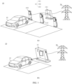
- a leakage current detection method is mainly as follows: Before parallel connection nodes of the plurality of AC-DC power conversion apparatuses are detected, a system leakage current is sampled by using a leakage current transformer, and the system may be directly protected by using the detected leakage current. Although this detection solution is simple and reliable, a specific location of failure cannot be identified in this leakage current detection method. When a failure occurs in the system, the entire system needs to be shut down for protection, leading to poor redundancy of the system.
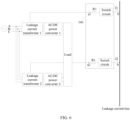
- a power conversion device includes a plurality of power converters and a plurality of leakage current sampling circuits. An input end of each power converter is configured to connect to a power supply, and an output end of each power converter is configured to connect to a load. The plurality of power converters are connected in parallel. The plurality of leakage current sampling circuits are in a one-to-one correspondence with the plurality of power converters. Each leakage current sampling circuit is configured to sample a leakage current of a corresponding power converter.
- the power conversion device is configured to: when a sum of leakage currents of the plurality of power converters is greater than a first current threshold, turn off at least some of first power converters, so that a sum of leakage currents of the plurality of power converters is less than or equal to the first current threshold.
- the first power converter is a power converter whose leakage current is greater than a second current threshold among the plurality of power converters.
- the first current threshold is a maximum leakage current allowed by the power conversion device
- the second current threshold is a maximum leakage current allowed by the first power converter.
- each power converter corresponds to one leakage current sampling circuit.
- one leakage current sampling circuit captures a leakage current of one power converter.
- the power conversion device may accurately identify a location of failure based on a leakage current of each power converter and the sum of the leakage currents of the plurality of power converters. Therefore, only a faulty component in the power conversion device needs to be turned off, and other normal components may still continue to operate. In this way, the power conversion device is protected.
- the first power converter whose leakage current is greater than the second current threshold among the plurality of power converters is turned off, so that a leakage current of the power conversion device meets an operation requirement. This can improve safety of the power conversion device.
- each power converter supports independent leakage current detection, when one of the power converters is turned off, normal operation of other power converters is not affected, in other words, the other power converters may still continue to operate. This can improve redundancy of the power conversion device.
- the power conversion device may turn off some of the first power converters, and a sum of leakage currents of power converters operating in the power conversion device is less than the maximum leakage current allowed by the power conversion device, so that a leakage current of the power conversion device can meet an operation requirement. This can improve safety of the power conversion device.
- the power conversion device may turn off all of the first power converters, and a sum of leakage currents of power converters in the power conversion device other than the first power converters is less than the maximum leakage current allowed by the power conversion device, so that a leakage current of the power conversion device can meet an operation requirement. This can improve safety of the power conversion device.
- the power conversion device because the power conversion device turns off all power converters whose leakage currents are greater than a leakage current allowed by the power conversion device, bodily harm can be avoided, and personal safety can be ensured.
- a leakage current transformer in an added leakage current sampling circuit only needs to be selected based on a current specification of a corresponding power converter.
- the leakage current transformer in the added leakage current sampling circuit only needs to have a capability of capturing a maximum leakage current of a corresponding power converter. Compared with a case in which one leakage current transformer is used to capture leakage currents of all power converters in a system, in this embodiment of this application, selection of a leakage current transformer in a leakage current sampling circuit is not greatly limited, and costs can also be reduced.
- parallel power converters when parallel power converters are added to the system, power converters may be directly combined, or power converters with different power levels may even be combined. This can improve flexibility and scalability of a parallel system.
- the power conversion device is further configured to: when a sum of leakage currents of the plurality of power converters is less than or equal to the first current threshold, turn off the first power converter; or when a sum of leakage currents of the plurality of power converters is less than or equal to the first current threshold, skip turning off the first power converter.
- the first power converter when the sum of the leakage currents of the plurality of power converters is less than or equal to the first current threshold, although the sum of the leakage currents of the plurality of power converters is less than the maximum leakage current allowed by the power conversion device, a leakage current of the first power converter is greater than the maximum leakage current allowed by the first power converter, and when insulation between a metal housing of the first power converter and an internal charged component fails, if the housing of the first power converter is not grounded and a human body is in contact with the housing, the leakage current flows into the ground through the human body, causing bodily harm. Therefore, in this case, the first power converter may be turned off, to avoid bodily harm and ensure personal safety.
- the power conversion device further includes a leakage current bus and an equalization circuit
- the leakage current sampling circuit includes a leakage current transformer.
- the leakage current transformer is configured to capture a leakage current of a corresponding power converter.
- An input end of the equalization circuit is connected to a plurality of leakage current transformers.
- An output end of the equalization circuit is connected to the leakage current bus.
- the equalization circuit is configured to average output values of the plurality of leakage current transformers and then output an average value.
- the power conversion device is configured to calculate a product of a leakage current corresponding to a voltage of the leakage current bus and a quantity of the plurality of power converters, to obtain the sum of the leakage currents of the plurality of power converters.
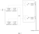
- the equalization circuit includes a plurality of equalization resistors and a plurality of switch circuits, and each leakage current transformer is connected to the leakage current bus through one equalization resistor and one switch circuit that are connected in series.
- each leakage current transformer is connected to the leakage current bus through one equalization resistor and one switch circuit that are connected in series. In this way, after an output value of each leakage current transformer passes through the equalization circuit, a value transmitted to the leakage current bus is an average value of sums of output values of the plurality of leakage current transformers. This helps the power conversion device calculate a sum of leakage currents of all power converters, to protect the power conversion device.
- the first operational amplifier is intended to isolate a circuit connected to an input end of the first operational amplifier from a circuit connected to an output end of the first operational amplifier.
- the circuit connected to the input end of the first operational amplifier and the circuit connected to the output end of the first operational amplifier do not affect each other. In this way, even if a node voltage in the circuit fluctuates, impact on a voltage value output by each leakage current transformer or a voltage value of the leakage current bus is small. This helps the power conversion device accurately obtain a leakage current of each power converter and a sum of all leakage currents. Further, this can improve accuracy of protecting the power conversion device.
- the switch circuit includes the two switching transistors, the current-limiting resistor, the first voltage source, and the drive circuit, and the drive circuit outputs different signals to control turn-on or turn-off of the switching transistors, to determine whether an output value of a leakage current transformer is to be transmitted to the leakage current bus.
- the drive circuit may output a high level, and control a switching transistor connected in series to the connection line connecting the equalization resistor and the leakage current bus to be turned off, so that an output value of a leakage current transformer corresponding to the power converter is not transmitted to the leakage current bus. This can avoid impact of the output value of the leakage current transformer on a system leakage current, and help the power conversion device obtain an accurate system leakage current. Further, this can improve accuracy of protecting the power conversion device.
- the switch circuit further includes a voltage-division resistor.
- One end of the voltage-division resistor is connected to an emitter of the other switching transistor.
- the other end of the voltage-division resistor is connected to a connection point between the current-limiting resistor and a collector of the other switching transistor.
- the voltage-division resistor is provided, and the first voltage source is grounded through the current-limiting resistor and the voltage-division resistor. Therefore, if a resistance of the voltage-division resistor is far greater than a resistance of the current-limiting resistor, the voltage-division resistor bears a large part of a voltage output by the first voltage source. In this way, a base voltage of one switching transistor can be reduced, to reduce a risk of damage to the switching transistor.
- the power conversion device further includes a plurality of controllers
- the leakage current sampling circuit further includes a plurality of voltage sampling circuits
- the plurality of voltage sampling circuits include a first voltage sampling circuit and a plurality of second voltage sampling circuits.
- the plurality of controllers are in a one-to-one correspondence with the plurality of power converters, and each controller is configured to control a corresponding power converter.
- Input ends of the plurality of first voltage sampling circuits are connected to the leakage current bus, an output end of each first voltage sampling circuit is connected to the controller in a one-to-one correspondence, and each first voltage sampling circuit is configured to capture a voltage value of the leakage current bus.
- each second voltage sampling circuit An input end of each second voltage sampling circuit is connected to a connection point between a corresponding leakage current transformer and the equalization circuit, an output end of each second voltage sampling circuit is connected to the controller in a one-to-one correspondence, and each second voltage sampling circuit is configured to capture a voltage value at a connection point between a corresponding leakage current transformer and the equalization circuit.
- each controller is connected to an output end of a first voltage sampling circuit, and each first voltage sampling circuit is configured to capture a voltage value of the leakage current bus, so that each controller can obtain the voltage value of the leakage current bus.
- each controller is connected to an output end of a corresponding second voltage sampling circuit, and each second voltage sampling circuit is configured to capture a voltage value of a connection point between a corresponding leakage current transformer and the equalization circuit, so that each controller can obtain a voltage value output by a corresponding leakage current transformer. In this way, each controller can obtain a voltage value of a corresponding leakage current transformer and a voltage value of the leakage current bus.
- each controller may derive a leakage current of a corresponding power converter and a sum of leakage currents of all power converters, to protect the power conversion device.
- each voltage sampling circuit includes a second operational amplifier, a first resistor, and a filter capacitor.
- a non-inverting input end of the second operational amplifier is an input end of the voltage sampling circuit.
- An inverting input end of the second operational amplifier is connected to an output end of the second operational amplifier.
- the output end of the second operational amplifier is connected to one end of the first resistor.
- the other end of the first resistor is connected to one end of the filter capacitor.
- the other end of the filter capacitor is grounded.
- a connection point between the other end of the first resistor and the filter capacitor is an output end of the voltage sampling circuit.
- the non-inverting input end of the second operational amplifier is the input end of the voltage sampling circuit, and the inverting input end of the second operational amplifier is connected to the output end of the second operational amplifier. Therefore, the output end of the second operational amplifier outputs a voltage value of the leakage current bus.
- the first resistor and the filter capacitor may filter a voltage output by the output end of the first operational amplifier, so that a voltage value captured by the controller is accurate. This helps the controller accurately control a status of a corresponding power converter.
- the first resistor may further limit a current. This can reduce a current flowing into a pin of a chip of the controller, to reduce a risk of damage to the pin of the chip.
- the equalization circuit averages the output values of the plurality of leakage current transformers and then outputs the average value, and the output end of the equalization circuit is connected to the leakage current bus. Therefore, the voltage value of the leakage current bus is the average value of the sums of the voltage values output by the plurality of leakage current transformers.
- the power conversion device only needs to derive a corresponding leakage current based on the voltage value of the leakage current bus, and multiply the leakage current by the quantity of the plurality of power converters to obtain the sum of the leakage currents of the plurality of power converters.
- the power conversion device can obtain the sum of the leakage currents of the plurality of power converters based only on the product of the leakage current corresponding to the voltage of the leakage current bus and the quantity of the plurality of power converters. This can reduce complexity of calculation.
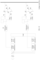
- the equalization circuit 340 includes a plurality of equalization resistors and a plurality of switch circuits, and each leakage current transformer is connected to the leakage current bus 330 through one equalization resistor and one switch circuit that are connected in series.
- the leakage current transformer 1 captures a leakage current of the AC/DC power converter 1, and a voltage value output by the leakage current transformer 1 is transmitted to an equalization circuit, and is transmitted to the leakage current bus 330 through one equalization resistor R1 and one switch circuit.
- the leakage current transformer 2 captures a leakage current of an AC/DC power converter 2, and a voltage value output by the leakage current transformer 2 is transmitted to the equalization circuit, and is transmitted to the leakage current bus 330 through one equalization resistor R1 and one switch circuit.
- each leakage current transformer is connected to the leakage current bus through one equalization resistor and one switch circuit that are connected in series. In this way, after an output value of each leakage current transformer passes through the equalization circuit, a value transmitted to the leakage current bus is an average value of sums of output values of the plurality of leakage current transformers. This helps the power conversion device calculate a sum of leakage currents of all power converters, to protect the power conversion device.
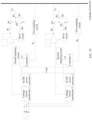
- the equalization circuit 340 further includes a plurality of first operational amplifiers.
- a non-inverting input end of each first operational amplifier is connected to a corresponding leakage current transformer.
- An inverting input end of each first operational amplifier is connected to an output end of the first operational amplifier.
- An output end of each first operational amplifier is connected to one end of the equalization resistor. The other end of the equalization resistor is connected to the leakage current bus through the switch circuit.
- FIG. 7 is a diagram of still another power conversion device according to an embodiment of this application.
- a leakage current transformer 1 is connected to a corresponding equalization resistor R1 through a corresponding first operational amplifier
- a leakage current transformer 2 is connected to a corresponding equalization resistor R1 through a corresponding first operational amplifier
- the equalization resistor R1 is connected to a leakage current bus through a switch circuit.
- a non-inverting input end of the first operational amplifier is connected to the leakage current transformer, and an inverting input end of the first operational amplifier is connected to an output end of the first operational amplifier. Therefore, a voltage at the non-inverting input end of the first operational amplifier is consistent with a voltage value at the output end of the first operational amplifier.
- an output value of the leakage current transformer 1 is input to the input end of the first operational amplifier, and the output end of the first operational amplifier also outputs the output value of the leakage current transformer 1.
- an output value of the leakage current transformer 2 is input to the input end of the first operational amplifier, and the output end of the first operational amplifier also outputs the output value of the leakage current transformer 2.
- the first operational amplifier is intended to isolate a circuit connected to the input end of the first operational amplifier from a circuit connected to the output end of the first operational amplifier.
- the circuit connected to the input end of the first operational amplifier and the circuit connected to the output end of the first operational amplifier do not affect each other. For example, fluctuation of a voltage of the circuit connected to the input end of the first operational amplifier does not affect a voltage value of the leakage current bus connected to the output end, or fluctuation of a voltage of the circuit connected to the output end of the first operational amplifier does not affect a voltage value of the leakage current transformer connected to the input end.
- the switch circuit includes a triode.
- a switch circuit includes two switching transistors Q1 and Q2, a current-limiting resistor R2, a first voltage source U1, and a drive circuit.
- One switching transistor Q1 is connected in series to a connection line connecting an equalization resistor R1 and a leakage current bus, and a base of the switching transistor Q1 is grounded through the other switching transistor Q2.
- the first voltage source U1 is connected to a connection point between the two switching transistors through the current-limiting resistor R2.
- the drive circuit is connected to a base of the other switching transistor Q2.
- each calibration circuit is configured to: during initial operation of the power conversion device, make output values of all the first voltage sampling circuits consistent when an input value of each leakage current transformer is a preset value. This can reduce a deviation, and help the power conversion device accurately obtain a leakage current of each power converter and a sum of all leakage currents. Further, this can improve accuracy of protecting the power conversion device.
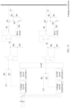
- FIG. 13 is a diagram of still another power conversion device according to an embodiment of this application.
- a calibration circuit includes a second resistor R6, a third resistor R7, a fourth resistor R8, a fifth resistor R9, a third operational amplifier, and a second voltage source U2.
- a non-inverting input end of the third operational amplifier is connected to the second voltage source through the second resistor.
- the non-inverting input end of the third operational amplifier is connected to a leakage current transformer through the third resistor.
- One end of the fourth resistor is connected to an output end of the third operational amplifier.
- the other end of the fourth resistor is grounded through the fifth resistor.
- An inverting input end of the third operational amplifier is connected to a connection point between the fourth resistor and the fifth resistor.
- resistances of the four resistors may be equal or unequal.
- resistances of the second resistor R6 and the third resistor R7 are equal, and resistances of the fourth resistor R8 and the fifth resistor R9 are equal.
- a difference between resistances of the second resistor R6 and the third resistor R7 is less than a preset value, and a difference between resistances of the fourth resistor R8 and the fifth resistor R9 is less than a preset value, where the preset value may be set randomly.
- a non-inverting input end of an operational amplifier is connected to an inverting input end of the operational amplifier, and the inverting input end of the third operational amplifier is connected to the output end of the third operational amplifier. Therefore, a voltage output by the output end of the third operational amplifier is also 2.0 V In other words, when a leakage current of an AC/DC power converter captured by a leakage current transformer is 0 mA, a voltage output by the calibration circuit is 2.0 V
- the calibration circuit includes four resistors, the third operational amplifier, and the second voltage source, and resistances of all the resistors are equal.
- a second voltage source connected to each leakage current transformer may provide a corresponding voltage according to a requirement, so that output values of all first voltage sampling circuits are consistent when an input value of each leakage current transformer is a preset value. This can reduce a deviation, and help the power conversion device accurately obtain a leakage current of each power converter and a sum of all leakage currents. Further, this can improve accuracy of protecting the power conversion device.
- the following further describes another manner of calculating a sum of leakage currents of a plurality of power converters included in a power conversion device.
- a leakage current sampling circuit includes a leakage current transformer, and a power conversion device further includes a summation circuit and a plurality of controllers.
- Each controller is configured to: obtain an output value of a corresponding leakage current transformer and an output value of the summation circuit; and turn on or turn off a corresponding power converter based on the output value of the leakage current transformer and the output value of the summation circuit.
- the summation circuit is configured to perform summation on the output values of all the leakage current transformers.
- the summation circuit may obtain an output value of a corresponding leakage current transformer from each controller, or may obtain an output value of a corresponding leakage current transformer from each leakage current transformer. Therefore, the summation circuit may perform summation based on the obtained output value of each leakage current transformer.
- each controller may obtain the output value of the summation circuit, and each controller may obtain an output value of a corresponding leakage current transformer. Therefore, each controller may turn on or turn off a corresponding power converter based on the output value of the leakage current transformer and the output value of the summation circuit.
- the controller 1 may further obtain a leakage current of 750 mA output by the summation circuit, so that the controller 1 can control turn-on or turn-off of the AC/DC power converter 1 based on the obtained leakage current of the AC/DC power converter 1 and the leakage current of 750 mA output by the summation circuit.
- the controller 2 may further obtain a leakage current of 750 mA output by the summation circuit, so that the controller 2 can control turn-on or turn-off of the AC/DC power converter 2 based on the obtained leakage current of the AC/DC power converter 2 and the leakage current of 750 mA output by the summation circuit.
- the summation circuit may be a hardware adder, a summation operator, or the like.
- a leakage current sampling circuit includes a leakage current transformer, and a power conversion device further includes a plurality of controllers.
- each controller may obtain an output value of a corresponding leakage current transformer, and broadcast the obtained output value of the corresponding leakage current transformer, so that each controller can further obtain an output of another leakage current transformer in the power conversion device in addition to an output value of a leakage current transformer corresponding to the controller.
- a voltage value corresponding to a leakage current of 0 mA is 2.0 V, and each time the leakage current increases by 250 mA, the voltage value increases by 0.1 V
- a controller 1 may learn that a leakage current of an AC/DC power converter 1 is 250 mA
- a controller 2 may learn that a leakage current of an AC/DC power converter 2 is 500 mA.
- the controller 1 and the controller 2 may respectively broadcast the leakage currents of the AC/DC power converters that are obtained by the controller 1 and the controller 2.
- a manner of broadcasting, by each controller, a leakage current of a power converter obtained by the controller is not specifically limited.
- the leakage current may be broadcast through wired communication or wireless communication.
- the wired communication may include a CAN.
- the wireless communication may include Wi-Fi, Bluetooth, and the like.
- a leakage current of a power converter may not be broadcast by a corresponding controller, but may be performed by a corresponding leakage current sampling circuit.
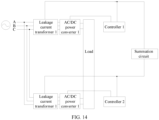
- a leakage current sampling circuit is located on an input side of a power converter.
- a location of a leakage current sampling circuit is not specifically limited in embodiments of this application.
- each leakage current sampling circuit is located at an output end of a power converter; or each leakage current sampling circuit is located at an input end of a power converter; or some leakage current sampling circuits of a plurality of leakage current sampling circuits each are located at an input end of a power converter, and a leakage current sampling circuit other than the some leakage current sampling circuits is located at an output end of a power converter.
- FIG. 17 is a diagram of still another power conversion device according to an embodiment of this application. As shown in FIG. 17 , a leakage current sampling circuit 1 is located at an input end of a power converter 1, and a leakage current sampling circuit 2 is located at an output end of the power converter 2. A specific operation principle of the leakage current sampling circuit is similar to that in the foregoing embodiments. Details are not described herein again.
Landscapes
- Engineering & Computer Science (AREA)
- Power Engineering (AREA)
- Transportation (AREA)
- Mechanical Engineering (AREA)
- Inverter Devices (AREA)
Applications Claiming Priority (1)
| Application Number | Priority Date | Filing Date | Title |
|---|---|---|---|
| CN202311762213.3A CN118399564A (zh) | 2023-12-19 | 2023-12-19 | 一种功率转换设备和充电桩 |
Publications (1)
| Publication Number | Publication Date |
|---|---|
| EP4580024A1 true EP4580024A1 (de) | 2025-07-02 |
Family
ID=91993114
Family Applications (1)
| Application Number | Title | Priority Date | Filing Date |
|---|---|---|---|
| EP24220991.4A Pending EP4580024A1 (de) | 2023-12-19 | 2024-12-18 | Leistungsumwandlungsvorrichtung und ladesäule |
Country Status (2)
| Country | Link |
|---|---|
| EP (1) | EP4580024A1 (de) |
| CN (1) | CN118399564A (de) |
Citations (2)
| Publication number | Priority date | Publication date | Assignee | Title |
|---|---|---|---|---|
| US20040189251A1 (en) * | 2003-03-28 | 2004-09-30 | Kutkut Nasser H. | Modular and reconfigurable rapid battery charger |
| EP3333005A1 (de) * | 2016-12-09 | 2018-06-13 | Dr. Ing. h.c. F. Porsche AG | Modulare leistungselektronik zum laden eines elektrisch betriebenen fahrzeugs |
-
2023
- 2023-12-19 CN CN202311762213.3A patent/CN118399564A/zh active Pending
-
2024
- 2024-12-18 EP EP24220991.4A patent/EP4580024A1/de active Pending
Patent Citations (2)
| Publication number | Priority date | Publication date | Assignee | Title |
|---|---|---|---|---|
| US20040189251A1 (en) * | 2003-03-28 | 2004-09-30 | Kutkut Nasser H. | Modular and reconfigurable rapid battery charger |
| EP3333005A1 (de) * | 2016-12-09 | 2018-06-13 | Dr. Ing. h.c. F. Porsche AG | Modulare leistungselektronik zum laden eines elektrisch betriebenen fahrzeugs |
Non-Patent Citations (2)
| Title |
|---|
| "Protection of Electrical Networks", 1 January 2006, JOHN WILEY & SONS, INC., ISBN: 978-1-905209-06-4, article CHRISTOPHE PREVE: "Protection of Network Elements", pages: 361 - 486, XP055298510, DOI: 10.1002/9780470612224.ch10 * |
| CHRISTOPHE PR?V?: "Protection Functions and their Applications", PROTECTION OF ELECTRICAL NETWORKS, 1 January 2006 (2006-01-01), pages 207 - 316, XP055698340, ISBN: 978-0-470-61222-4, Retrieved from the Internet <URL:https://onlinelibrary.wiley.com/doi/pdfdirect/10.1002/9780470612224.ch7> [retrieved on 20200526], DOI: 10.1002/9780470612224 * |
Also Published As
| Publication number | Publication date |
|---|---|
| CN118399564A (zh) | 2024-07-26 |
Similar Documents
| Publication | Publication Date | Title |
|---|---|---|
| US11594917B2 (en) | Overvoltage protection device and method thereof | |
| US11320481B2 (en) | High voltage interlock circuit and detection method | |
| EP3817232B1 (de) | Ansteuerungsschaltung für nmos-schalter und stromversorgungsvorrichtung | |
| CN105099001B (zh) | 用于无接触地传输能量的装置 | |
| KR20150057946A (ko) | 전원관리유닛 및 이를 응용하는 무선전력시스템 | |
| US20250183790A1 (en) | Power conversion device and protection method for power conversion device | |
| CN110036547A (zh) | 低电压断路器设备 | |
| CN112959964A (zh) | 一种电机控制模块的供电系统及车辆 | |
| EP4580024A1 (de) | Leistungsumwandlungsvorrichtung und ladesäule | |
| US20240106015A1 (en) | Power supply system and method for charging a power supply system | |
| CN113162009A (zh) | 一种过能保护电路、剩余电流装置、电子设备和配电盒 | |
| US11283366B2 (en) | Rectifier arrangement | |
| CN211880080U (zh) | 本安型供电电路及本安型通信网络设备 | |
| WO2025082171A1 (zh) | 直流变换器以及光伏系统 | |
| CN103847532A (zh) | 用于电动车辆的电能管理装置和方法 | |
| KR20250042113A (ko) | 재폐쇄기 동작을 이용한 전환 스위치 시스템 및 방법 | |
| CN117937705A (zh) | 一种功率转换装置及充电设备 | |
| US20190228925A1 (en) | Electrical circuit breaker assembly | |
| US11791719B2 (en) | Device, method, and system for resolving common-mode voltage interference | |
| US20240364100A1 (en) | Overcurrent protection based on slope detection | |
| TWI914780B (zh) | 用於固態電池斷接及保護系統的控制電路 | |
| CN210041670U (zh) | 直流电源电路 | |
| EP4447244A1 (de) | Schutzschalter | |
| US20260018877A1 (en) | Multiport protection apparatus | |
| JP7852418B2 (ja) | コンバータ装置、および、コンバータ装置の制御方法 |
Legal Events
| Date | Code | Title | Description |
|---|---|---|---|
| PUAI | Public reference made under article 153(3) epc to a published international application that has entered the european phase |
Free format text: ORIGINAL CODE: 0009012 |
|
| STAA | Information on the status of an ep patent application or granted ep patent |
Free format text: STATUS: THE APPLICATION HAS BEEN PUBLISHED |
|
| AK | Designated contracting states |
Kind code of ref document: A1 Designated state(s): AL AT BE BG CH CY CZ DE DK EE ES FI FR GB GR HR HU IE IS IT LI LT LU LV MC ME MK MT NL NO PL PT RO RS SE SI SK SM TR |
|
| STAA | Information on the status of an ep patent application or granted ep patent |
Free format text: STATUS: REQUEST FOR EXAMINATION WAS MADE |
|
| 17P | Request for examination filed |
Effective date: 20260102 |