EP4580060A1 - Magnetschalter - Google Patents
Magnetschalter Download PDFInfo
- Publication number
- EP4580060A1 EP4580060A1 EP23472010.0A EP23472010A EP4580060A1 EP 4580060 A1 EP4580060 A1 EP 4580060A1 EP 23472010 A EP23472010 A EP 23472010A EP 4580060 A1 EP4580060 A1 EP 4580060A1
- Authority
- EP
- European Patent Office
- Prior art keywords
- component
- threshold
- switch
- magnetic field
- measurement
- Prior art date
- Legal status (The legal status is an assumption and is not a legal conclusion. Google has not performed a legal analysis and makes no representation as to the accuracy of the status listed.)
- Pending
Links
Images

Classifications
-
- H—ELECTRICITY
- H03—ELECTRONIC CIRCUITRY
- H03K—PULSE TECHNIQUE
- H03K17/00—Electronic switching or gating, i.e. not by contact-making and –breaking
- H03K17/94—Electronic switching or gating, i.e. not by contact-making and –breaking characterised by the way in which the control signals are generated
- H03K17/965—Switches controlled by moving an element forming part of the switch
- H03K17/97—Switches controlled by moving an element forming part of the switch using a magnetic movable element
-
- H—ELECTRICITY
- H03—ELECTRONIC CIRCUITRY
- H03K—PULSE TECHNIQUE
- H03K17/00—Electronic switching or gating, i.e. not by contact-making and –breaking
- H03K17/94—Electronic switching or gating, i.e. not by contact-making and –breaking characterised by the way in which the control signals are generated
- H03K17/945—Proximity switches
- H03K17/95—Proximity switches using a magnetic detector
- H03K17/9512—Proximity switches using a magnetic detector using digital techniques
-
- H—ELECTRICITY
- H03—ELECTRONIC CIRCUITRY
- H03K—PULSE TECHNIQUE
- H03K17/00—Electronic switching or gating, i.e. not by contact-making and –breaking
- H03K17/94—Electronic switching or gating, i.e. not by contact-making and –breaking characterised by the way in which the control signals are generated
- H03K17/945—Proximity switches
- H03K17/95—Proximity switches using a magnetic detector
-
- H—ELECTRICITY
- H03—ELECTRONIC CIRCUITRY
- H03K—PULSE TECHNIQUE
- H03K17/00—Electronic switching or gating, i.e. not by contact-making and –breaking
- H03K17/51—Electronic switching or gating, i.e. not by contact-making and –breaking characterised by the components used
- H03K17/90—Electronic switching or gating, i.e. not by contact-making and –breaking characterised by the components used by the use, as active elements, of galvano-magnetic devices, e.g. Hall-effect devices
-
- H—ELECTRICITY
- H03—ELECTRONIC CIRCUITRY
- H03K—PULSE TECHNIQUE
- H03K17/00—Electronic switching or gating, i.e. not by contact-making and –breaking
- H03K17/94—Electronic switching or gating, i.e. not by contact-making and –breaking characterised by the way in which the control signals are generated
- H03K17/945—Proximity switches
- H03K17/95—Proximity switches using a magnetic detector
- H03K17/9517—Proximity switches using a magnetic detector using galvanomagnetic devices
-
- H—ELECTRICITY
- H03—ELECTRONIC CIRCUITRY
- H03K—PULSE TECHNIQUE
- H03K17/00—Electronic switching or gating, i.e. not by contact-making and –breaking
- H03K17/94—Electronic switching or gating, i.e. not by contact-making and –breaking characterised by the way in which the control signals are generated
- H03K17/965—Switches controlled by moving an element forming part of the switch
- H03K17/97—Switches controlled by moving an element forming part of the switch using a magnetic movable element
- H03K2017/9713—Multiposition, e.g. involving comparison with different thresholds
-
- H—ELECTRICITY
- H03—ELECTRONIC CIRCUITRY
- H03K—PULSE TECHNIQUE
- H03K2217/00—Indexing scheme related to electronic switching or gating, i.e. not by contact-making or -breaking covered by H03K17/00
- H03K2217/94—Indexing scheme related to electronic switching or gating, i.e. not by contact-making or -breaking covered by H03K17/00 characterised by the way in which the control signal is generated
- H03K2217/965—Switches controlled by moving an element forming part of the switch
- H03K2217/9651—Switches controlled by moving an element forming part of the switch the moving element acting on a force, e.g. pressure sensitive element
Definitions
- Magnetic field sensors which use magnetic field sensing elements. These applications include current sensors that senses a magnetic field generated by a current through a conductor, position sensors for detecting position of a magnetic source, for example a rotation detector that senses passing of a magnetically sensitive materials such as gear teeth and the like.
- the switch further comprises comparing means adapted for comparing the measurement signal with a respective threshold value.
- the switch comprises signal processing means for providing a measurement signal of the measurement of a first component and/or of at least a second component.
- the measurement signal may be representative of the absolute value of the respective component of the magnetic field in at least one direction.
- the switch further comprises one or more integrated magnetic concentrators for redirecting the magnetic field in at least one predetermined direction being the direction of maximum sensitivity of the Hall element.
- the switch is configured to provide an output signal being either the first output corresponding to a measurement of a component being higher that the respective threshold value, or the result of the last comparison.
- the switch is adapted to stop the comparison sequence when the signal representative of the result of at least one comparison is provided.
- a proximity sensing system can be provided with a simple and reliable magnetic sensor as a magnetic switch.
- the magnetic field of the magnet may be between 0.5 mT to 100 mT.
- the present invention relates to a magnetic switch, including a magnetic field sensing system for detecting or sensing magnetic fields.
- Existing methods entail measuring the magnetic field and comparing it with the threshold, to check if the object is close enough to trigger a response of the switch.
- measuring the magnetic field of the object is usually done by obtaining signals depending on each of the magnetic field components, e.g. Bx, By, Bz in a 3D case.
- the signals need to be processed to obtain whether the object is close enough or not.
- the signals need to be compared in a look-up table (LUT). This requires a look-up table with a large amount of data, or a drastic simplification of the model.
- a 'measurement signal' of a field component or a 'measurement' for short, reference is made to the signal provided by the sensing system representative of the value of the magnetic field for that component.
- the measurement signal represents the magnitude and the direction (e.g. the polarity, as positive and negative), however in some embodiments it may represent only the magnitude or absolute value, without information on polarity.
- FIG. 1 shows a region A, defined by magnetic field magnitude thresholds a and b in the directions of Bx and By respectively, wherein the point 10 represents zero value of the magnetic field.
- This is a simplified model, where each measured magnetic field component of an object 11, 12 is compared to the predetermined thresholds a, b.
- the magnetic field of the objects 11 and 12 is represented by the vectors B 11 and B 12 in the magnetic field plane, which vectors have two components, one in the direction of Bx and the other in the direction of By, which are then compared to the thresholds a and b, respectively. It is apparent that such simplified model may lead to switching at different field strengths.
- a magnetic field with small By component will switch when its strength is close to the threshold a in the other, Bx, direction.
- At least one threshold for comparison with a further measurement is obtained from a previous measurement of the field in a previous direction.
- the second and/or third thresholds for subsequent directions can be obtained from measurements made in previous iterations.
- the sensing sequence starts with the measurement of a first component Bx of the magnetic field.
- the rest of components By, Bz can be also measured at this stage, or could be measured at any point before the relevant comparison, for example after obtaining the output indicating that a comparison with a component in a different direction may be needed.
- the 3D switch can be programmed to perform, as an example:
- the 3D switch is programmed to perform:
- Thz is a constant value regardless of the values of Bx and By.
- the maximum value of Thz may be used, instead of a different threshold value per measurement signal, in order to cover all the potential measurement signals that could correspond to values over the threshold.
- the components could be compared rather than their absolute value, including information of the polarity (the signs) and comparing them with the threshold as explained earlier.
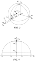
- the volume would be a cylinder if the relationship between the other two components is that of a circumference (either as a function or as values stored in the LUT).
- the first threshold and another threshold are fixed at a predetermined value, and the remaining further threshold is based on at least one measurement previously performed.
- Thz equal to a function of the absolute value of any one of the previous measurement, f(Abs(Bx)) or f(Abs(By)). These correspond to provide a particular area (e.g. a circle) in the x-z plane or in the y-z plane respectively (e.g. stored as a LUT).
- Table 5 with n rows Bx Thy 0 Val0 ⁇ ⁇ Bxi Vali
- Table 6 with n rows Axis (Bx, By, or Bz) Thx, Thy, or Thz 0 Val0 ⁇ ⁇ Bxi, Byi or Bzi Vali
- the switch may be programmed to execute the following algorithm:
- the two thresholds for one direction Z can be obtained, each from the measurement of the field component in each of the previous directions X, Y.
- the comparing means is configured to provide a third threshold based on the measurement of different components of the magnetic field.
- the third threshold may be provided sequentially, based on the measurement of different components of the magnetic field.
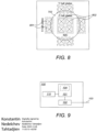
- the system may comprise a magnetic sensor including sensing elements which are adapted to provide the required signals, e.g. two or three signals representative of the field components in two respectively three different directions. This can be provided in a single chip.
- horizontal and vertical Hall plates may be provided in combination, optionally including one or more magnetic concentrators (e.g. integrated Magnetic Concentrator (IMC)).
- IMC integrated Magnetic Concentrator
- the Hall plates and optionally MCs may be combined to provide the required signals representative of the field components in the required directions, for example two or three different directions.
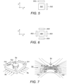
- FIG. 5 shows a horizontal Hall plate 501 combined with two vertical Hall plates 502, 503 which can be used as part of the magnetic field sensing system in accordance with some embodiments of the present invention. They may be configured so that the signal provided by them represents the magnetic field components in 3 different directions, e.g. three perpendicular directions.
- the vertical plates 502, 503 are sensitive to the field in X, Y directions and the horizontal plate 501 is sensitive to the vertical component Z of the field.
- FIG. 6 shows an alternative embodiment wherein two vertical plates 602, 603 are sensitive to one horizontal component X and two other vertical plates 604, 605 are sensitive to a horizontal component Y in different direction, e.g. perpendicular, to the previous component X. These can be used to obtain different combinations of the signals from the field if required, for example to reduce external influences such as noise and the like.
- magnetic concentrators MC can be used, e.g. an integrated MC, in combination with Hall plates.
- FIG. 7 shows a perspective view on the left, and a cross section on the right, of a sensing system with one or more Hall plates 701 distributed through the surface, to obtain differential fields for example.
- the IMC provides field component conversion, so the horizontal component of the field (e.g. Bx) can be converted into a combination of a parallel component B// and perpendicular component B1.
- the perpendicular components are detectable by the horizontal Hall plates 703, 704.
- the threshold can be provided with an input of two previous measurements, or with any one of the previous measurements.
- the first and any one of the further thresholds may have a fixed value, as long as at least one threshold is obtained from a previous measurement or measurements.
- the method may comprise providing the third threshold based on the measurement of different components of the magnetic field. For example, the value of one of the previous measurements, or of both, can be taken into account. in some embodiments, the third threshold may be provided sequentially based on the measurement of different components of the field.
Landscapes
- Measuring Magnetic Variables (AREA)
Priority Applications (3)
| Application Number | Priority Date | Filing Date | Title |
|---|---|---|---|
| EP23472010.0A EP4580060A1 (de) | 2023-12-28 | 2023-12-28 | Magnetschalter |
| US18/975,447 US20250219638A1 (en) | 2023-12-28 | 2024-12-10 | Magnetic switch |
| CN202411954423.7A CN120238112A (zh) | 2023-12-28 | 2024-12-27 | 磁开关 |
Applications Claiming Priority (1)
| Application Number | Priority Date | Filing Date | Title |
|---|---|---|---|
| EP23472010.0A EP4580060A1 (de) | 2023-12-28 | 2023-12-28 | Magnetschalter |
Publications (1)
| Publication Number | Publication Date |
|---|---|
| EP4580060A1 true EP4580060A1 (de) | 2025-07-02 |
Family
ID=89854488
Family Applications (1)
| Application Number | Title | Priority Date | Filing Date |
|---|---|---|---|
| EP23472010.0A Pending EP4580060A1 (de) | 2023-12-28 | 2023-12-28 | Magnetschalter |
Country Status (3)
| Country | Link |
|---|---|
| US (1) | US20250219638A1 (de) |
| EP (1) | EP4580060A1 (de) |
| CN (1) | CN120238112A (de) |
Citations (4)
| Publication number | Priority date | Publication date | Assignee | Title |
|---|---|---|---|---|
| US20150046117A1 (en) * | 2012-03-01 | 2015-02-12 | Tyco Electronics Amp Gmbh | Method for contactlessly measuring a relative position by means of a 3d hall sensor having measurement signal store |
| WO2017030772A1 (en) * | 2015-08-19 | 2017-02-23 | Allegro Microsystems, Llc | Magnetic field sensor to detect a magnitude of a magnetic field in any direction |
| US20170307407A1 (en) * | 2013-05-24 | 2017-10-26 | Allegro Microsystems, Llc | Magnetic Field Sensor To Detect A Magnitude Of A Magnetic Field In Any Direction |
| US20230098109A1 (en) * | 2021-09-29 | 2023-03-30 | Semtech Corporation | Environmental sensor |
-
2023
- 2023-12-28 EP EP23472010.0A patent/EP4580060A1/de active Pending
-
2024
- 2024-12-10 US US18/975,447 patent/US20250219638A1/en active Pending
- 2024-12-27 CN CN202411954423.7A patent/CN120238112A/zh active Pending
Patent Citations (4)
| Publication number | Priority date | Publication date | Assignee | Title |
|---|---|---|---|---|
| US20150046117A1 (en) * | 2012-03-01 | 2015-02-12 | Tyco Electronics Amp Gmbh | Method for contactlessly measuring a relative position by means of a 3d hall sensor having measurement signal store |
| US20170307407A1 (en) * | 2013-05-24 | 2017-10-26 | Allegro Microsystems, Llc | Magnetic Field Sensor To Detect A Magnitude Of A Magnetic Field In Any Direction |
| WO2017030772A1 (en) * | 2015-08-19 | 2017-02-23 | Allegro Microsystems, Llc | Magnetic field sensor to detect a magnitude of a magnetic field in any direction |
| US20230098109A1 (en) * | 2021-09-29 | 2023-03-30 | Semtech Corporation | Environmental sensor |
Also Published As
| Publication number | Publication date |
|---|---|
| CN120238112A (zh) | 2025-07-01 |
| US20250219638A1 (en) | 2025-07-03 |
Similar Documents
| Publication | Publication Date | Title |
|---|---|---|
| KR101737765B1 (ko) | 가동체의 이중적인 절대 위치 결정을 위한 장치 및 방법 | |
| US8718964B2 (en) | Method and system for calibrating current sensors | |
| US9835472B2 (en) | Using cartesian coordinates for position detection with a magnetic sensor | |
| US5461311A (en) | Rod axial position detector including plural scales wherein nonmagnetized portions have differing spacing and differing depths and means for calculating the absolute position are provided | |
| RU2727565C1 (ru) | Способ измерения тока и устройство для измерения тока | |
| US20110025313A1 (en) | Measurement Method, Sensor Arrangement and Measurement System | |
| JP2018072344A (ja) | 磁気センサを用いた多次元測定システムならびに関連するシステム、方法、および集積回路 | |
| WO2013153015A1 (en) | Displacement sensor for contactlessly measuring a relative position by means of a magnetic field sensor array on the basis of the hall effect | |
| CN110412339B (zh) | 一种电力系统电流测量装置及方法 | |
| CN110044388B (zh) | 一种旋转体的非接触式绝对角度位置传感器的使用方法 | |
| Weiss et al. | Current measurement of flat conductors with a circular array of magnetic sensors | |
| EP4580060A1 (de) | Magnetschalter | |
| JP6947194B2 (ja) | 信号処理回路および磁気センサシステム | |
| US10215593B2 (en) | Magnetic sensor | |
| US20240210211A1 (en) | Magnetic switch and proximity sensing | |
| US11789092B2 (en) | Magnetic sensor devices, systems and methods with error detection | |
| CN111982122A (zh) | 一种基于霍尔传感器的磁导航传感器及其检测方法 | |
| CN117250395A (zh) | 电流检测装置及电子设备 | |
| US20240067018A1 (en) | Device for automatic positioning of a charge plug | |
| CN107621224B (zh) | 用于计算三相系统的相移或幅度的方法 | |
| US12525853B2 (en) | Synchronous sampling | |
| EP1074815A1 (de) | Biaxialer magnetischer Positionssensor | |
| US12339695B2 (en) | Stray field robust magnetic sensor system for detecting a state of a tiltable and rotatable object | |
| CN111341712B (zh) | 一种晶片位置校准装置及方法 | |
| CN106813688B (zh) | 数据检测装置 |
Legal Events
| Date | Code | Title | Description |
|---|---|---|---|
| PUAI | Public reference made under article 153(3) epc to a published international application that has entered the european phase |
Free format text: ORIGINAL CODE: 0009012 |
|
| STAA | Information on the status of an ep patent application or granted ep patent |
Free format text: STATUS: THE APPLICATION HAS BEEN PUBLISHED |
|
| AK | Designated contracting states |
Kind code of ref document: A1 Designated state(s): AL AT BE BG CH CY CZ DE DK EE ES FI FR GB GR HR HU IE IS IT LI LT LU LV MC ME MK MT NL NO PL PT RO RS SE SI SK SM TR |
|
| STAA | Information on the status of an ep patent application or granted ep patent |
Free format text: STATUS: REQUEST FOR EXAMINATION WAS MADE |
|
| 17P | Request for examination filed |
Effective date: 20251010 |