EP4580078A1 - Procédé et dispositif de configuration de tci unifiée dans un système de communication utilisant de multiples points de transmission et de réception - Google Patents
Procédé et dispositif de configuration de tci unifiée dans un système de communication utilisant de multiples points de transmission et de réception Download PDFInfo
- Publication number
- EP4580078A1 EP4580078A1 EP23886400.3A EP23886400A EP4580078A1 EP 4580078 A1 EP4580078 A1 EP 4580078A1 EP 23886400 A EP23886400 A EP 23886400A EP 4580078 A1 EP4580078 A1 EP 4580078A1
- Authority
- EP
- European Patent Office
- Prior art keywords
- tci state
- panel
- base station
- panels
- tci
- Prior art date
- Legal status (The legal status is an assumption and is not a legal conclusion. Google has not performed a legal analysis and makes no representation as to the accuracy of the status listed.)
- Pending
Links
Images





Classifications
-
- H—ELECTRICITY
- H04—ELECTRIC COMMUNICATION TECHNIQUE
- H04W—WIRELESS COMMUNICATION NETWORKS
- H04W72/00—Local resource management
- H04W72/20—Control channels or signalling for resource management
- H04W72/23—Control channels or signalling for resource management in the downlink direction of a wireless link, i.e. towards a terminal
- H04W72/231—Control channels or signalling for resource management in the downlink direction of a wireless link, i.e. towards a terminal the control data signalling from the layers above the physical layer, e.g. RRC or MAC-CE signalling
-
- H—ELECTRICITY
- H04—ELECTRIC COMMUNICATION TECHNIQUE
- H04B—TRANSMISSION
- H04B7/00—Radio transmission systems, i.e. using radiation field
- H04B7/02—Diversity systems; Multi-antenna system, i.e. transmission or reception using multiple antennas
- H04B7/04—Diversity systems; Multi-antenna system, i.e. transmission or reception using multiple antennas using two or more spaced independent antennas
- H04B7/06—Diversity systems; Multi-antenna system, i.e. transmission or reception using multiple antennas using two or more spaced independent antennas at the transmitting station
- H04B7/0613—Diversity systems; Multi-antenna system, i.e. transmission or reception using multiple antennas using two or more spaced independent antennas at the transmitting station using simultaneous transmission
- H04B7/0615—Diversity systems; Multi-antenna system, i.e. transmission or reception using multiple antennas using two or more spaced independent antennas at the transmitting station using simultaneous transmission of weighted versions of same signal
- H04B7/0619—Diversity systems; Multi-antenna system, i.e. transmission or reception using multiple antennas using two or more spaced independent antennas at the transmitting station using simultaneous transmission of weighted versions of same signal using feedback from receiving side
- H04B7/0621—Feedback content
- H04B7/0628—Diversity capabilities
-
- H—ELECTRICITY
- H04—ELECTRIC COMMUNICATION TECHNIQUE
- H04B—TRANSMISSION
- H04B7/00—Radio transmission systems, i.e. using radiation field
- H04B7/02—Diversity systems; Multi-antenna system, i.e. transmission or reception using multiple antennas
- H04B7/04—Diversity systems; Multi-antenna system, i.e. transmission or reception using multiple antennas using two or more spaced independent antennas
- H04B7/0404—Diversity systems; Multi-antenna system, i.e. transmission or reception using multiple antennas using two or more spaced independent antennas the mobile station comprising multiple antennas, e.g. to provide uplink diversity
-
- H—ELECTRICITY
- H04—ELECTRIC COMMUNICATION TECHNIQUE
- H04B—TRANSMISSION
- H04B7/00—Radio transmission systems, i.e. using radiation field
- H04B7/02—Diversity systems; Multi-antenna system, i.e. transmission or reception using multiple antennas
- H04B7/04—Diversity systems; Multi-antenna system, i.e. transmission or reception using multiple antennas using two or more spaced independent antennas
- H04B7/0413—MIMO systems
-
- H—ELECTRICITY
- H04—ELECTRIC COMMUNICATION TECHNIQUE
- H04B—TRANSMISSION
- H04B7/00—Radio transmission systems, i.e. using radiation field
- H04B7/02—Diversity systems; Multi-antenna system, i.e. transmission or reception using multiple antennas
- H04B7/04—Diversity systems; Multi-antenna system, i.e. transmission or reception using multiple antennas using two or more spaced independent antennas
- H04B7/06—Diversity systems; Multi-antenna system, i.e. transmission or reception using multiple antennas using two or more spaced independent antennas at the transmitting station
- H04B7/0686—Hybrid systems, i.e. switching and simultaneous transmission
- H04B7/0691—Hybrid systems, i.e. switching and simultaneous transmission using subgroups of transmit antennas
-
- H—ELECTRICITY
- H04—ELECTRIC COMMUNICATION TECHNIQUE
- H04B—TRANSMISSION
- H04B7/00—Radio transmission systems, i.e. using radiation field
- H04B7/02—Diversity systems; Multi-antenna system, i.e. transmission or reception using multiple antennas
- H04B7/04—Diversity systems; Multi-antenna system, i.e. transmission or reception using multiple antennas using two or more spaced independent antennas
- H04B7/06—Diversity systems; Multi-antenna system, i.e. transmission or reception using multiple antennas using two or more spaced independent antennas at the transmitting station
- H04B7/0686—Hybrid systems, i.e. switching and simultaneous transmission
- H04B7/0695—Hybrid systems, i.e. switching and simultaneous transmission using beam selection
- H04B7/06952—Selecting one or more beams from a plurality of beams, e.g. beam training, management or sweeping
- H04B7/06956—Selecting one or more beams from a plurality of beams, e.g. beam training, management or sweeping using a selection of antenna panels
-
- H—ELECTRICITY
- H04—ELECTRIC COMMUNICATION TECHNIQUE
- H04W—WIRELESS COMMUNICATION NETWORKS
- H04W8/00—Network data management
- H04W8/22—Processing or transfer of terminal data, e.g. status or physical capabilities
- H04W8/24—Transfer of terminal data
Definitions
- the present disclosure relates to improved communication technology, and more particularly, to a transmission technology of a multiple transmission and reception point (MTRP).
- MTRP multiple transmission and reception point
- Communication networks are being developed to provide improved communication services compared to existing communication networks (e.g., LTE (long term evolution), LTE-A (advanced), etc.).
- a 5G communication network e.g., NR (new radio) communication network
- NR new radio
- the 5G communication network can support various communication services and scenarios compared to an LTE communication network.
- usage scenarios of the 5G communication network may include eMBB (enhanced Mobile BroadBand), URLLC (Ultra Reliable Low Latency Communication), mMTC (massive Machine Type Communication), etc.
- 6G communication networks can support various communication services and scenarios compared to 5G communication networks.
- 6G communication networks can satisfy requirements of ultra-performance, ultra-bandwidth, ultra-space, ultra-precision, ultra-intelligence, and/or ultra-reliability.
- 6G communication networks can support various and wide frequency bands and can be applied to various usage scenarios (e.g., terrestrial communication, non-terrestrial communication, sidelink communication, etc.).
- a joint TCI state indication may be configured for a first panel of the UE and the DL channel separate TCI state indication and the UL channel separate TCI state indication may be configured for a second panel of the UE.
- signaling may be at least one of higher layer signaling, MAC signaling, or PHY (physical) signaling.
- a message used for higher layer signaling may be referred to as a "higher layer message” or a “higher layer signaling message”.
- a message used for MAC signaling may be referred to as a "MAC message” or a "MAC signaling message”.
- a message used for PHY signaling may be referred to as a "PHY message” or a "PHY signaling message”.
- Higher layer signaling may mean a transmission and reception operation of system information (e.g., MIB (master information block), SIB (system information block)) and/or RRC message.
- MAC signaling may mean a transmission and reception operation of MAC CE (control element).
- PHY signaling may mean a transmission and reception operation of control information (e.g., DCI (downlink control information), UCI (uplink control information), SCI (sidelink control information)).
- the plurality of communication nodes 110 to 130 may support a communication protocol specified in a 3rd generation partnership project (3GPP) standard (e.g., LTE communication protocol, LTE-A communication protocol, NR communication protocol, etc.).
- the plurality of communication nodes 110 to 130 may support CDMA (code division multiple access) technology, WCDMA (wideband CDMA) technology, TDMA (time division multiple access) technology, FDMA (frequency division multiple access) technology, OFDM (orthogonal frequency division multiplexing) technology, Filtered OFDM technology, CP (cyclic prefix)-OFDM technology, DFT-s-OFDM (discrete Fourier transform-spread-OFDM) technology, OFDMA (orthogonal frequency division multiple access) technology, SC (single carrier)-FDMA technology, NOMA (non-orthogonal multiple access) technology, GFDM (generalized frequency division multiplexing) technology, FBMC (filter bank multi-carrier) technology, UFMC (universal filtered multi-car
- FIG. 2 is a block diagram illustrating a first embodiment of a communication node constituting a communication system.
- the communication node 200 may include at least one processor 210, a memory 220, and a transmission/reception device 230 connected to a network to perform communication.
- the communication node 200 may further include an input interface device 240, an output interface device 250, a storage device 260, etc.
- Each component included in the communication node 200 may be connected by a bus 270 to perform communication with each other.
- the processor 210 may execute a program command stored in at least one of the memory 220 and the storage device 260.
- the processor 210 may mean a central processing unit (CPU), a graphics processing unit (GPU), or a dedicated processor on which methods according to embodiments of the present disclosure are performed.
- Each of the memory 220 and the storage device 260 may be composed of at least one of a volatile storage medium and a nonvolatile storage medium.
- the memory 220 may be composed of at least one of a read only memory (ROM) and a random access memory (RAM).
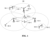
- the communication system 100 may include a plurality of base stations 110-1, 110-2, 110-3, 120-1 and 120-2 and a plurality of terminals 130-1, 130-2, 130-3, 130-4, 130-5 and 130-6.
- Each of the first base station 110-1, the second base station 110-2, and the third base station 110-3 may form a macro cell.
- Each of the fourth base station 120-1 and the fifth base station 120-2 may form a small cell.
- the fourth base station 120-1, the third terminal 130-3, and the fourth terminal 130-4 may be within the cell coverage of the first base station 110-1.
- the second terminal 130-2, the fourth terminal 130-4, and the fifth terminal 130-5 may be within the cell coverage of the second base station 110-2.
- the fifth base station 120-2, the fourth terminal 130-4, the fifth terminal 130-5, and the sixth terminal 130-6 may be within the cell coverage of the third base station 110-3.
- the first terminal 130-1 may be within the cell coverage of the fourth base station 120-1.
- the sixth terminal 130-6 may be within the cell coverage of the fifth base station 120-2.
- each of the plurality of base stations 110-1, 110-2, 110-3, 120-1 and 120-2 may be referred to as a NodeB (NB), an evolved NodeB (eNB), a gNB, an advanced base station (ABS), a high reliability-base station (HR-BS), a base transceiver station (BTS), a radio base station, a radio transceiver, an access point, an access node, a radio access station (RAS), a mobile multihop relay-base station (MMR-BS), a relay station (RS), an advanced relay station (ARS), a high reliability-relay station (HR-RS), a home NodeB (HNB), a home eNodeB (HeNB), a road side unit (RSU), a radio remote head (RRH), a transmission point (TP), a transmission and reception point (TRP), etc.
- NB NodeB
- eNB evolved NodeB
- gNB an advanced base station
- HR-BS high reliability-base station
- Each of the plurality of terminals 130-1, 130-2, 130-3, 130-4, 130-5 and 130-6 may be referred to as a user equipment (UE), terminal equipment (TE), advanced mobile station (AMS), high reliability-mobile station (HR-MS), terminal, access terminal, mobile terminal, station, subscriber station, mobile station, portable subscriber station, node, device, OBU (on board unit), etc.
- UE user equipment
- TE terminal equipment
- AMS advanced mobile station
- HR-MS high reliability-mobile station
- each of the plurality of base stations 110-1, 110-2, 110-3, 120-1 and 120-2 may support MIMO transmission (e.g., single user (SU)-MIMO, multi user (MU)-MIMO, massive MIMO, etc.), coordinated multipoint (CoMP) transmission, carrier aggregation (CA) transmission, transmission in an unlicensed band, sidelink communication (e.g., device to device communication (D2D), proximity services (ProSe)), Internet of Things (IoT) communication, dual connectivity (DC), etc.
- MIMO transmission e.g., single user (SU)-MIMO, multi user (MU)-MIMO, massive MIMO, etc.
- CoMP coordinated multipoint
- CA carrier aggregation
- sidelink communication e.g., device to device communication (D2D), proximity services (ProSe)
- IoT Internet of Things
- DC dual connectivity
- each of the plurality of terminals 130-1, 130-2, 130-3, 130-4, 130-5 and 130-6 may perform an operation corresponding to the base station 110-1, 110-2, 110-3, 120-1 and 120-2 and an operation supported by the base station 110-1, 110-2, 110-3, 120-1 and 120-2.
- the second base station 110-2 may transmit a signal to the fourth terminal 130-4 based on the SU-MIMO method, and the fourth terminal 130-4 may receive a signal from the second base station 110-2 by the SU-MIMO method.
- the second base station 110-2 may transmit signals to the fourth terminal 130-4 and the fifth terminal 130-5 based on the MU-MIMO method, and each of the fourth terminal 130-4 and the fifth terminal 130-5 may receive signals from the second base station 110-2 by the MU-MIMO method.
- Each of the first base station 110-1, the second base station 110-2, and the third base station 110-3 may transmit a signal to the fourth terminal 130-4 based on the CoMP method, and the fourth terminal 130-4 may receive a signal from the first base station 110-1, the second base station 110-2, and the third base station 110-3 based on the CoMP method.
- Each of the plurality of base stations 110-1, 110-2, 110-3, 120-1 and 120-2 may transmit and receive a signal to and from the terminals 130-1, 130-2, 130-3, 130-4, 130-5 and 130-6 within its cell coverage based on the CA method.
- Each of the first base station 110-1, the second base station 110-2, and the third base station 110-3 may control sidelink communication between the fourth terminal 130-4 and the fifth terminal 130-5, and each of the fourth terminal 130-4 and the fifth terminal 130-5 may perform sidelink communication under the control of the second base station 110-2 and the third base station 110-3.
- FIG. 3 is a block diagram illustrating a first embodiment of communication nodes performing communication.
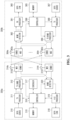
- each of a first communication node 300a and a second communication node 300b may be a base station or a UE.
- the first communication node 300a may transmit a signal to the second communication node 300b.
- a transmission processor 311 included in the first communication node 300a may receive data (e.g., a data unit) from a data source 310.
- the transmission processor 311 may receive control information from a controller 316.
- the control information may include at least one of system information, RRC configuration information (e.g., information configured by RRC signaling), MAC control information (e.g., MAC CE), or PHY control information (e.g., DCI, SCI).
- the transmission processor 311 may perform a processing operation (e.g., an encoding operation, a symbol mapping operation, etc.) on data to generate data symbol(s).
- the transmission processor 311 may perform a processing operation (e.g., an encoding operation, a symbol mapping operation, etc.) on control information to generate control symbol(s).
- the transmission processor 311 may generate synchronization/reference symbol(s) for a synchronization signal and/or a reference signal.
- a Tx MIMO processor 312 may perform a spatial processing operation (e.g., a precoding operation) on data symbol(s), control symbol(s), and/or synchronization/reference symbol(s).
- Output (e.g., a symbol stream) of the Tx MIMO processor 312 may be provided to modulators (MODs) included in transceivers 313a to 313t.
- the modulators (MODs) may perform a processing operation on the symbol stream to generate modulation symbols, and may perform an additional processing operation (e.g., an analog conversion operation, an amplification operation, a filtering operation, an up-conversion operation) on the modulation symbols to generate signals.
- the signals generated by the modulators (MODs) of the transceivers 313a to 313t may be transmitted via antennas 314a to 314t.
- the signals transmitted by the first communication node 300a may be received by the antennas 364a to 364r of the second communication node 300b.
- the signals received by the antennas 364a to 364r may be provided to demodulators (DEMODs) included in the transceivers 363a to 363r.
- the demodulator (DEMOD) may perform a processing operation (e.g., a filtering operation, an amplification operation, a down-conversion operation, a digital conversion operation) on the signal to obtain samples.
- the demodulator (DEMOD) may perform an additional processing operation on the samples to obtain symbols.
- a MIMO detector 362 may perform a MIMO detection operation on the symbols.
- the reception processor 361 may perform a processing operation (e.g., a deinterleaving operation, a decoding operation) on the symbols.
- the output of the reception processor 361 may be provided to a data sink 360 and the controller 366.
- data may be provided to the data sink 360 and control information may be provided to the controller 366.
- the second communication node 300b may transmit a signal to the first communication node 300a.
- a transmission processor 368 included in the second communication node 300b may receive data (e.g., data unit) from a data source 367 and perform a processing operation on the data to generate data symbol(s).
- the transmission processor 368 may receive control information from the controller 366 and perform a processing operation on the control information to generate control symbol(s).
- the transmission processor 368 may perform a processing operation on a reference signal to generate reference symbol(s).
- the Tx MIMO processor 369 may perform a spatial processing operation (e.g., a precoding operation) on data symbol(s), control symbol(s), and/or reference symbol(s). Output (e.g., a symbol stream) of the Tx MIMO processor 369 may be provided to modulators (MODs) included in transceivers 363a to 363t.
- the modulators (MODs) may perform processing operations on the symbol stream to generate modulation symbols, and may perform additional processing operations (e.g., an analog conversion operation, an amplification operation, a filtering operation, an up-conversion operation) on the modulation symbols to generate signals.
- the signals generated by the modulators (MODs) of the transceivers 363a to 363t may be transmitted via the antennas 364a to 364t.
- the signals transmitted by the second communication node 300b may be received by the antennas 314a to 314r of the first communication node 300a.
- the signals received by the antennas 314a to 314r may be provided to the demodulators (DEMODs) included in transceivers 313a to 313r.
- the demodulator (DEMOD) may perform a processing operation (e.g., a filtering operation, an amplification operation, a down-conversion operation, a digital conversion operation) on the signal to obtain samples.
- the demodulator (DEMOD) may perform an additional processing operation on the samples to obtain symbols.
- a MIMO detector 320 may perform a MIMO detection operation on the symbols.
- the reception processor 319 may perform a processing operation (e.g., a deinterleaving operation, a decoding operation) on the symbols.
- the output of the reception processor 319 may be provided to a data sink 318 and the controller 316.
- data may be provided to the data sink 318 and control information may be provided to the controller 316.
- Memories 315 and 365 may store data, control information, and/or program code.
- a scheduler 317 may perform a scheduling operation for communication.
- the processors 311, 312, 319, 361, 368 and 369 and the controllers (316, 366) illustrated in FIG. 3 may be the processor 210 illustrated in FIG. 2 and may be used to perform the methods described in the present disclosure.
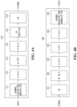
- FIG. 4a is a block diagram illustrating a first embodiment of a transmission path
- FIG. 4b is a block diagram illustrating a first embodiment of a reception path.
- the receiving path 420 may include a down-converter (DC) 421, a CP removal block 422, an S-to-P block 423, an N FFT block 424, a P-to-S block 425, and a channel decoding and demodulation block 426.
- DC down-converter
- CP CP removal block
- N N FFT block
- P-to-S block 425 P-to-S block 425
- a channel decoding and demodulation block 426 may be a natural number.
- information bits may be input to the channel coding and modulation block 411.
- the channel coding and modulation block 411 may perform a coding operation (e.g., low-density parity check (LDPC) coding operation, polar coding operation, etc.) and a modulation operation (e.g., Quadrature Phase Shift Keying (QPSK), Quadrature Amplitude Modulation (QAM), etc.) on the information bits.
- a coding operation e.g., low-density parity check (LDPC) coding operation, polar coding operation, etc.
- a modulation operation e.g., Quadrature Phase Shift Keying (QPSK), Quadrature Amplitude Modulation (QAM), etc.
- QPSK Quadrature Phase Shift Keying
- QAM Quadrature Amplitude Modulation
- each of the blocks may be implemented by at least one of hardware, software, or firmware.
- some of the blocks may be implemented by software, and the remaining blocks may be implemented by hardware or a "combination of hardware and software.”
- one block may be subdivided into multiple blocks, multiple blocks may be integrated into one block, some blocks may be omitted, and blocks supporting other functions may be added.
- FIG. 6 is a conceptual diagram illustrating a first embodiment of a subframe in a communication system.
- FIG. 7 is a conceptual diagram illustrating a first embodiment of a slot in a communication system.
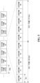
- one slot may include one or more symbols.
- One slot illustrated in FIG. 7 may include 14 symbols.
- the length of the slot may vary depending on the number of symbols included in the slot and the length of the symbol. Alternatively, the length of the slot may vary depending on the numerology.
- the numerology applied to the physical signal and channel in the communication system may vary.
- the numerology may vary to meet various technical requirements of the communication system.
- the numerology may include a subcarrier spacing and a CP length (or a CP type).
- Table 1 may be a first embodiment of a numerology configuration method for a CP-OFDM-based communication system. At least some of the numerologies in Table 1 may be supported depending on the frequency band on which the communication system operates. Additionally, in the communication system, numerology(s) not listed in Table 1 may be further supported.
- the length of the slot may be 1 ms. In this case, one system frame may include 10 slots.
- a symbol may be set as a downlink (DL) symbol, a flexible (FL) symbol, or an uplink (UL) symbol.
- DL slot A slot consisting of only DL symbols may be referred to as a "DL slot”
- FL slot a slot consisting of only FL symbols
- UL slot a slot consisting of only UL symbols
- the slot format may be semi-fixedly set by higher layer signaling (e.g., RRC signaling).
- Information indicating the semi-fixed slot format may be included in system information, and the semi-fixed slot format may be set cell-specifically.
- the semi-fixed slot format may be additionally set for each terminal through terminal-specific higher layer signaling (e.g., RRC signaling).
- a flexible symbol of a slot format set cell-specifically may be overridden with a downlink symbol or an uplink symbol by terminal-specific higher layer signaling.
- the slot format may be dynamically indicated by physical layer signaling (e.g., a slot format indicator (SFI) included in DCI).
- SFI slot format indicator
- a semi-fixedly set slot format may be overridden by a dynamically indicated slot format. For example, a flexible symbol set semi-fixedly may be overridden with a downlink symbol or an uplink symbol by SFI.
- a reference signal may be a channel state information-reference signal (CSI-RS), a sounding reference signal (SRS), a demodulation-reference signal (DM-RS), a phase tracking-reference signal (PT-RS), etc.
- a channel may be a physical broadcast channel (PBCH), a physical downlink control channel (PDCCH), a physical downlink shared channel (PDSCH), a physical uplink control channel (PUCCH), a physical uplink shared channel (PUSCH), a physical sidelink control channel (PSCCH), a physical sidelink shared channel (PSSCH), etc.
- a control channel may mean a PDCCH, a PUCCH, or a PSCCH
- a data channel may mean a PDSCH, a PUSCH, or a PSSCH.
- FIG. 8 is a conceptual diagram illustrating a first embodiment of a time-frequency resource in a communication system.
- a resource consisting of one symbol (e.g., OFDM symbol) in the time domain and one subcarrier in the frequency domain may be defined as a "RE (resource element)".
- Resources consisting of one OFDM symbol in the time domain and K subcarriers in the frequency domain may be defined as a "REG (resource element group)".
- a REG may include K REs.
- the REG may be used as a basic unit of resource allocation in the frequency domain.
- K may be a natural number.
- K may be 12.
- N may be a natural number.
- N may be 14.
- N OFDM symbols may be used as a basic unit of resource allocation in the time domain.
- the terminal may perform a monitoring operation for the PDCCH in order to receive the PDSCH transmitted from the base station.
- the base station may inform the terminal of the configuration information for the monitoring operation of the PDCCH using a higher layer message (e.g., an RRC (radio resource control) message).
- the configuration information for the monitoring operation of the PDCCH may include CORESET (control resource set) information and search space information.
- the CORESET information may include PDCCH DMRS (demodulation reference signal) information, PDCCH precoding information, PDCCH occasion information, etc.
- the PDCCH DMRS may be a DMRS used to demodulate the PDCCH.
- the PDCCH occasion may be an area where the PDCCH may be present. That is, the PDCCH occasion may be an area where DCI may be transmitted.
- the PDCCH occasion may be referred to as a PDCCH candidate.
- the PDCCH occasion information may include time resource information and frequency resource information of the PDCCH occasion.
- the length of the PDCCH occasion in the time domain may be indicated in symbol units.
- the size of the PDCCH occasion in the frequency domain may be indicated in RB units (for example, in PRB (physical resource block) units or CRB (common resource block) units).
- the search space information may include a CORESET ID (identifier) associated with the search space, a period of PDCCH monitoring, and/or an offset. Each of the period of PDCCH monitoring and the offset may be indicated in slot units.
- the search space information may further include an index of a symbol at which a PDCCH monitoring operation starts.
- the base station may configure a BWP (bandwidth part) for downlink communication.
- the BWP may be configured differently for each terminal.
- the base station may inform the terminal of the configuration information of the BWP using upper layer signaling.
- the upper layer signaling may mean "transmission operation of system information" and/or "transmission operation of RRC (radio resource control) message.”
- the number of BWPs configured for one terminal may be 1 or more.
- the terminal may receive the configuration information of the BWP from the base station, and may identify the BWP(s) configured by the base station based on the configuration information of the BWP.
- the base station may activate one or more BWPs among the plurality of BWPs.
- the base station may transmit the configuration information of the activated BWP(s) to the terminal using at least one of upper layer signaling, MAC (medium access control) CE (control element), or DCI.
- the base station may perform downlink communication using the activated BWP(s).
- the terminal may identify the activated BWP(s) by receiving configuration information of the activated BWP(s) from the base station, and perform a downlink reception operation in the activated BWP(s).
- the Multiple Transmission and Reception Point (MTRP) technology refers to a technique in which a base station (e.g., gNB) communicates with a terminal by utilizing multiple transmission reception points (TRPs) that are physically separated.
- the MTRP technology may solve the problem of reduced quality-of-service (QoS) when a terminal located at the cell edge is far from the base station by utilizing multiple TRPs, and at the same time solve the problem of inter-cell interference received from base stations located in different cells.
- QoS quality-of-service
- the MTPR technology may play a role in providing an additional communication path, which is a non-line-of-sight (NLOS) path, from the base station in cases where the line-of-sight (LOS) path from the base station is limited, such as in the millimeter wave band.
- NLOS non-line-of-sight
- CJT Coherent Joint Transmission
- NCJT Non-Coherent Joint Transmission
- the CJT method based on a stable backhaul link between a TRP and a connected base station, and two or more TRPs may support data transmission to a single terminal by cooperating with each other in a synchronized manner.
- the NCJT method is a method that determines scheduling, precoding matrix selection, modulation, and coding schemes without cooperation between the TRPs in a situation where two or more TRPs support a single terminal.
- the definition of beam management for TRP in 5G NR may be defined as a set of L1/L2 procedures that find or maintain an optimal beam required for transmission/reception of each TRP and terminal.
- the beam management procedures may be broadly classified into four types as follows.
- the TRP and the UE may utilize the reciprocity characteristics of downlink (DL)/uplink (UL) channels during beam management.
- the UE may utilize the values measured at the receive (Rx) beams of the DL channel when configuring the transmit (Tx) beam.
- the UE may utilize the values measured at the transmit (Tx) beams of the UL channel when configuring the receive (Rx) beam.
- these procedures for configuring the transmit beam and the receive beam may be performed in the same manner as in the UE.
- a transmission configuration indicator (TCI) has been introduced for beam management related to analog beamforming.
- the TCI may be used to configure a beam to be used for transmission of a specific channel and/or signal, for example, a PDSCH and/or CSI-RS and/or a PDCCH.
- the base station may dynamically indicate quasi-colocation (QCL) information to the UE by transmitting TCI through downlink control information (DCI).
- QCL quasi-colocation
- 3GGP Rel-17 introduced a TCI configuration method utilizing a unified TCI pool, or in other words, a unified TCI framework, to reduce signaling overhead for QCL configuration of DL and/or UL channels and to simplify multi-beam operation compared to previous releases of 3GGP Rel-16.
- the base station may pre-configure a common TCI pool that may be commonly used (or applied) to DL channels and UL channels through RRC signaling.
- the base station may directly indicate the TCI for DL channels and UL channels in the configured common TCI pool using the medium access control (MAC) control element (CE) (MAC-CE)/downlink control information (DCI).
- the base station may support update for the common TCI state.
- the common TCI state may be indicated (or set) for multiple component carriers (CCs).
- a reference CC among the multiple CCs may be additionally set, and TCI updates for other CCs within the indicated list may be performed simultaneously through a TCI update command for the reference CC.
- the above three methods may be divided into a joint TCI state indication method that commonly indicates the DL channel and the UL channel, and a separate TCI state indication method that separately sets the TCI for each DL channel or UL channel.
- the fundamental difference between the above two division methods may be whether or not there is reciprocity between the DL channel and the UL channel.
- Unified TCI framework was designed to target a single TRP (sTRP) in 3GPP Rel-17. However, it is targeted to expand to a multi-TRP (mTRP) system in 3GPP Rel-18.
- sTRP single TRP
- mTRP multi-TRP
- the TCI pool maybe configured using the above two methods.
- a user equipment (UE) 901, a first TRP 911, and a second TRP 912 are illustrated.
- the UE 901 may perform bidirectional (DL and UL) communication using a first TRP 911 and a first channel 921, and may perform bidirectional (DL and UL) communication using a second TRP 912 and a second channel 922.
- CJT-type communication or NCJT-type communication may be performed.
- the first TCI state pool 930 may be composed of a DL TCI state pool 931 and a DL TCI state pool 932 or may be composed of a joint TCI state pool 933.
- the first TCI state pool 930 is not composed of all of the DL TCI state pool 931, the DL TCI state pool 932 and the joint TCI state pool 933.
- a DL TCI state 931 and a UL TCI state 932 may be activated for the first TRP 911, and a DL TCI state 941 and a UL TCI state 942 may be activated for the second TRP 912.
- four TCI states may be activated in the UE 901.
- the base station and the UE may report the measurement results of the channel for beam management in units of panels, and even in UL transmission, such as STxMO, the UE may transmit the UL channel using the panel supported by the UE at the same time. Therefore, a technology for configuring the TCI state considering the panel in the UE is additionally required.
- the present disclosure described below will describe a unified TCI framework before Rel-17, which targets a single TRP, and a TCI configuration/indication method considering multiple panels on the MTRP environment and the UE side.
- the unified TRI framework may be largely divided into three procedures.
- Step 1 The base station may transmit candidates for the TCI state, for example, DL/UL/Joint state list, indicating QCL/spatial relation information for DL channels and UL channels on the UE side, via RRC.
- the TCI state transmitted via RRC may be transmitted by CC or CC group via reference CC.
- Step 3 The base station may indicate a specific TCI state to the UE for a target channel, such as a PDSCH, via DCI.
- a target channel such as a PDSCH
- the present disclosure described below will describe a unified TCI framework suitable for a terminal having multiple panels when utilizing all or some of the three-step procedures above.
- the base station may determine a TCI state that may be indicated (or set) to the UE. Then, the base station may transmit the determined TCI state information to the UE through RRC. At this time, the base station may preconfigure the TCI state for the joint TCI state or the separated TCI state in the serving cell configuration, and transmit the configuration information to the UE.
- the UE may use a TCI state pool that may be used for DL channel transmission when transmitting an UL channel.
- the base station shall separately configure a TCI state pool for a separate UL channel through a UE specific configuration for UL BWP. Then, the base station may transmit the TCI state pool information configured for the UL channel to the UE. In this case, the base station may configure the TCI pool for the UL channel of the UE without considering the terminal panel.
- FIG. 10 is a conceptual diagram explaining a TCI state pool configuration considering panels of a UE.
- a base station may know the panel number information of a UE.
- the base station may request UE capability information from the UE using a UE Capability Information enquiry message.
- the UE may transmit its capability information (UE Capability Information) to the base station.
- the UE capability information may include information such as the number of panels the UE has, the number of ports, the number of layers, and delay.
- the base station may obtain the panel number information of the UE.
- the base station may configure multiple TCI state pools based on the obtained panel number information of the UE.
- the base station may transmit TCI state pool information configured for each of the multiple panels to the UE.
- a TCI state pool 1000 may be composed of a joint TCI state pool 1010 or may be composed of a DL TCI state pool 1020 and a UL TCI state pool 1030.
- the TCI state pool 1000 is not composed of all of the j oint TCI state pool 1010, the DL TCI state pool 1020 and the UL TCI state pool 1030.
- the base station may divide the joint TCI state pool 1010 into a joint TCI state pool 1011 for panel 1 and a joint TCI state pool 1012 for panel 2 and transmit TCI state pool information to the UE.
- the base station may transmit DL TCI state pool 1020 information to the UE.
- the DL TCI state pool 1020 information may include DL TCI state pool 1021 information for panel 1 and DL TCI state pool 1022 information for panel 2.
- the base station may transmit UL TCI state pool 1030 information to the UE.
- the UL TCI state pool 1030 information may include UL TCI state pool 1031 information for panel 1 and UL TCI state pool 1032 information for panel 2.
- the base station may configure DL TCI state pools and DL TCI state pools for each of the panels and transmit them to the UE.
- the base station When a separated TCI state is set, the base station shall distinguish TCI state pools 1021 and 1022 for each panel in the DL TCI state pool 1020, and shall distinguish TCI state pools 1031 and 1032 for each panel in the UL TCI state pool 1030. Accordingly, each of the state pools may be mapped to TCI state pools in descending order of the panel index.
- This index mapping will be described as an example. Assume that the first panel index of the UE is "0" and the second panel index of the UE is "1". Also, assume that the index of the DL TCI state pool 1021 information for the first panel of the DL TCI state pool 1020 is "00" and the index of the DL TCI state pool 1022 for the panel of the DL TCI state pool 1020 is "01". Also, assume that the index of the UL TCI state pool 1031 information for the first panel of the UL TCI state pool 1030 is "10" and the index of the DL TCI state pool 1022 for the second panel of the UL TCI state pool 1030 is "11".
- the first panel and the DL TCI state pool 1021 for the first panel may be mapped to "000".
- the second panel and the TCI state pool 1022 for the second panel may be mapped to "001".
- the first panel and the UL TCI state pool 1031 for the first panel may be mapped to "010”
- the second panel and the UL TCI state pool 1032 for the second panel may be mapped to "111”.
- the index mapping using 3 bits has been described above. However, if there are two panels of the UE, they may be mapped to 2 bits if it is agreed in advance between the base station and the UE to sort them in descending order of the panel index.
- an identifier may be assigned to each panel, and the ID and TCI state pools may be mapped. It should be noted that the mapping of the panels of the UE described above and the TCI state pools for each of the UL channel and DL channel is only an example, and the present disclosure is not limited thereto.
- the base station when transferring a single TCI state pool to the UE as before, the base station (or UE) may be expected to perform reception or transmission without distinguishing the TCI state pool by panel. Therefore, when the base station transmits multiple TCI state pools to the UE, the base station (or UE) may be expected to apply the TCI state to the target channel by panel.
- the base station may configure a joint TCI state pool for a specific panel and a separated TCI state pool for another panel.
- the base station may configure a joint TCI state pool for a first panel of the UE and a separated TCI state pool for a second panel of the UE.
- the TCI states described in the present disclosure may also be supported in the case of carrier aggregation (CA) and/or dual connectivity (DC).
- CA and/or DC the base station may activate or deactivate the TCI state for the serving cell and/or CCs through a single signaling using a MAC-CE.
- the base station providing the CA and/or DC service shall transmit to the UE a combination of serving cells for activating or deactivating the TCI state for the serving cell and/or CCs through a single signaling.
- the combination of serving cells may be written as a single list, as shown in Table 2 below. [Table 2] simultaneousU-TCI-UpdateList1, simultaneousU-TCI-UpdateList2, simultaneousU-TCI-UpdateList3, simultaneousU-TCI-UpdateList4
- Each of "simultaneousU-TCI-UpdateList1", “simultaneousU-TCI-UpdateList2", “simultaneousU-TCI-UpdateList3" and “simultaneousU-TCI-UpdateList4" may include one or more cell groups.
- each of the lists may be mapped 1:1 with a master cell group and/or secondary cell groups. Accordingly, each list may include only one cell or may contain two or more cells.
- the activation or deactivation of the TCI state may also be performed.
- the lists shown in Table 2 may be configured regardless of the number of panels included in the UE.
- a suitable serving cell may differ between the panels of the UE. This is because the locations of the panels included in the UE are different, and each panel may have a different serving cell due to geographical location or obstacles in the communication path. Accordingly, the list of serving cells shown in Table 2 may also need to be configured for each panel. In other words, a list for a combination of serving cells may be needed for each panel of the UE.
- the present disclosure proposes a method for providing a list of combinations of serving cells for each panel.
- a set of lists for each panel may be additionally configured separately.
- one list may be additionally configured for each panel.
- a list of combinations of serving cells for panel 1 and a list of combinations of serving cells for panel 2 may be configured as shown in Table 3 below.
- Table 3 List of serving cells for panel 1 simultaneousU-TCI-UpdateList #1_1, simultaneousU-TCI-UpdateList #1_2, simultaneousU-TCI-UpdateList #1_3, simultaneousU-TCI-UpdateList #1_4 List of serving cells for panel 2 simultaneousU-TCI-UpdateList #2_1, simultaneousU-TCI-UpdateList #2_2, simultaneousU-TCI-UpdateList #2_3, simultaneousU-TCI-UpdateList #2_4
- step S1332 the base station 1302 may transmit the DCI generated in step S1330 to the UE 1301. Therefore, in step S1332, the UE 1301 may receive the DCI and obtain TCI state information included in the DCI. At this time, as described above, the UE 1301 may receive the DCI through the CC configured for each panel.
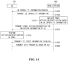
- FIG. 14 is a flowchart for a case where a base station instructs on/off at least one of the panels of a UE according to the present disclosure.
- a UE 1401 and a base station 1402 are illustrated.
- the UE 1401 and the base station 1402 illustrated in FIG. 14 may have the same configuration as described in FIG. 13 . Therefore, description of the overlapping configurations will be omitted.
- step S1400 the base station 1402 may transmit a UE capability information Enquiry message to the UE 1401. Accordingly, the UE 1401 may receive the UE capability information Enquiry message.
- the UE 1401 may generate UE capability information in response to the UE capability information enquiry message and transmit it to the base station 1402.
- the UE capability information may include information such as the number of panels the UE has, the number of ports, the number of layers, and delay. Accordingly, the base station 1402 may obtain information on the number of panels the UE has, which is included in the UE capability information.
- the base station 1402 may generate panel activation or deactivation instruction information of the UE based on the UE capability information.
- the activation/deactivation indication may use a MAC-CE or DCI as described above. It should be noted that the embodiment of FIG. 14 exemplifies a case of using the MAC-CE. In the case of using the MAC-CE, an implicit method or an explicit method may be used as described in the above section.
- the base station 1402 may transmit a MAC-CE including the panel activation/deactivation indication information of the UE to the UE 1401. Therefore, the UE 1401 may obtain the panel activation/deactivation instruction information based on the MAC-CE transmitted by the base station 1402 in step S1412.
- the base station 1402 may transmit DCI including TCI state information to the UE 1401. Therefore, the UE 1401 may receive the DCI transmitted by the base station 1402. In addition, the UE may obtain TCI state information included in the received DCI.
- the base station 1402 may transmit data via DL based on the DCI transmitted in step S1402. At this time, if the base station 1402 transmits data using two or more TRPs, data may be transmitted for each TRP. In addition, the base station 1402 may transmit data based on the TCI state configured for each panel of the UE 1401. Therefore, the UE 1401 may receive data through different TRPs for each panel.
- each of steps S1320 and S1322 of FIG. 13 may include each of steps S1410 and S1412 described in FIG. 14 .
- step S1320 of FIG. 13 may include step S1410 described in FIG. 14
- step S1322 of FIG. 13 may include step S1412 described in FIG. 14 .
- steps S1410 and S1412 of FIG. 14 are included in FIG. 13 , panel on/off of the UE may be indicated together.
- the operation of the method according to the present disclosure may be implemented as a computer-readable program or code on a computer-readable recording medium.
- the computer-readable recording medium includes all types of recording devices that store information that can be read by a computer system.
- the computer-readable recording medium may be distributed over network-connected computer systems so that the computer-readable program or code may be stored and executed in a distributed manner.
- the computer-readable recording medium may include a hardware device specially configured to store and execute program instructions, such as ROM, RAM, flash memory, etc.
- the program instructions may include not only machine language codes generated by a compiler, but also high-level language codes that can be executed by a computer using an interpreter, etc.
- a block or device corresponds to a method step or a feature of a method step.
- aspects described in the context of a method may also be described as a feature of a corresponding block or item or a corresponding device.
- Some or all of the method steps may be performed by (or using) a hardware device, such as, for example, a microprocessor, a programmable computer or an electronic circuit. In some embodiments, at least one or more of the most significant method steps may be performed by such a device.
- a programmable logic device e.g., a field-programmable gate array
- a field-programmable gate array may operate with a microprocessor to perform one of the methods described in the present disclosure. In general, the methods are preferably performed by some hardware device.
Landscapes
- Engineering & Computer Science (AREA)
- Computer Networks & Wireless Communication (AREA)
- Signal Processing (AREA)
- Databases & Information Systems (AREA)
- Mobile Radio Communication Systems (AREA)
Applications Claiming Priority (2)
| Application Number | Priority Date | Filing Date | Title |
|---|---|---|---|
| KR20220146341 | 2022-11-04 | ||
| PCT/KR2023/017591 WO2024096706A1 (fr) | 2022-11-04 | 2023-11-03 | Procédé et dispositif de configuration de tci unifiée dans un système de communication utilisant de multiples points de transmission et de réception |
Publications (1)
| Publication Number | Publication Date |
|---|---|
| EP4580078A1 true EP4580078A1 (fr) | 2025-07-02 |
Family
ID=90931063
Family Applications (1)
| Application Number | Title | Priority Date | Filing Date |
|---|---|---|---|
| EP23886400.3A Pending EP4580078A1 (fr) | 2022-11-04 | 2023-11-03 | Procédé et dispositif de configuration de tci unifiée dans un système de communication utilisant de multiples points de transmission et de réception |
Country Status (4)
| Country | Link |
|---|---|
| EP (1) | EP4580078A1 (fr) |
| KR (1) | KR20240064576A (fr) |
| CN (1) | CN120113161A (fr) |
| WO (1) | WO2024096706A1 (fr) |
Family Cites Families (1)
| Publication number | Priority date | Publication date | Assignee | Title |
|---|---|---|---|---|
| EP4224769A4 (fr) * | 2020-09-29 | 2024-11-06 | LG Electronics Inc. | Procédé et dispositif de transmission et de réception de liaison montante dans un système de communication sans fil |
-
2023
- 2023-11-03 EP EP23886400.3A patent/EP4580078A1/fr active Pending
- 2023-11-03 KR KR1020230151190A patent/KR20240064576A/ko active Pending
- 2023-11-03 WO PCT/KR2023/017591 patent/WO2024096706A1/fr not_active Ceased
- 2023-11-03 CN CN202380071913.XA patent/CN120113161A/zh active Pending
Also Published As
| Publication number | Publication date |
|---|---|
| KR20240064576A (ko) | 2024-05-13 |
| CN120113161A (zh) | 2025-06-06 |
| WO2024096706A1 (fr) | 2024-05-10 |
Similar Documents
| Publication | Publication Date | Title |
|---|---|---|
| US11863364B2 (en) | Method and apparatus for performing initial access in wireless communication system | |
| KR20240164429A (ko) | 단일 trp와 다중 trp 간의 스위칭의 방법 및 장치 | |
| EP4580078A1 (fr) | Procédé et dispositif de configuration de tci unifiée dans un système de communication utilisant de multiples points de transmission et de réception | |
| EP4626117A1 (fr) | Procédé et dispositif d'activation / de désactivation de tci dans un système mtrp | |
| EP4694490A1 (fr) | Procédé et appareil d'indication d'un état tci dans un système de communication | |
| EP4664786A1 (fr) | Procédé et dispositif de détermination de faisceaux dans un système de communication | |
| EP4675937A1 (fr) | Procédé et appareil pour la transmission d'un signal de liaison montante dans un système de communication | |
| EP4734391A1 (fr) | Procédé et dispositif de gestion de faisceaux dans un système multi-trp | |
| EP4580268A1 (fr) | Procédé et dispositif de commande de puissance de liaison montante dans un système de communication prenant en charge un mtrp | |
| US20250373375A1 (en) | Method and device for data transmission and reception in mobile communication system in mtrp environment | |
| EP4604654A1 (fr) | Procédé et dispositif d'attribution de ressources à de multiples points d'émission et de réception dans un système de communication sans fil | |
| KR20240128623A (ko) | 통신 시스템에서 다중 송수신점을 이용한 통신 방법 및 장치 | |
| KR20250063765A (ko) | 무선 통신 시스템에서 다중 송수신점 환경을 위한 전력 헤드룸 보고를 송신하기 위한 방법 및 장치 | |
| KR20250023926A (ko) | Trp 환경에서 상향링크 데이터 전송 방법 및 장치 | |
| KR20240164430A (ko) | Trp 스위칭의 적용 방법 및 장치 | |
| KR20250023294A (ko) | 다중 trp 시스템에서 빔 스위칭의 방법 및 장치 | |
| KR20250063232A (ko) | 통신 시스템에서 mpe 보고의 방법 및 장치 | |
| KR20250046223A (ko) | 무선 통신 시스템에서 상향링크 신호 전송 방식 전환을 위한 방법 및 장치 | |
| KR20250046199A (ko) | 다중 trp 통신에서 trp 스위칭의 방법 및 장치 | |
| KR20240018395A (ko) | Mtrp 환경의 이동 통신 시스템에서 빔 복구 방법 및장치 | |
| KR20250046200A (ko) | 다중 trp 통신에서 tci 상태의 업데이트 방법 및 장치 | |
| KR20250126600A (ko) | 비대칭 trp 시스템에서 전력 제어의 방법 및 장치 | |
| KR20250023316A (ko) | 무선 통신 시스템에서 상향링크 신호 전송 방식 전환을 위한 방법 및 장치 | |
| KR20250023927A (ko) | 통신 시스템에서 상향링크 송신 방법 및 장치 | |
| KR20250063234A (ko) | 통신 시스템에서 상향링크 채널의 전송 방법 및 장치 |
Legal Events
| Date | Code | Title | Description |
|---|---|---|---|
| STAA | Information on the status of an ep patent application or granted ep patent |
Free format text: STATUS: THE INTERNATIONAL PUBLICATION HAS BEEN MADE |
|
| PUAI | Public reference made under article 153(3) epc to a published international application that has entered the european phase |
Free format text: ORIGINAL CODE: 0009012 |
|
| STAA | Information on the status of an ep patent application or granted ep patent |
Free format text: STATUS: REQUEST FOR EXAMINATION WAS MADE |
|
| 17P | Request for examination filed |
Effective date: 20250324 |
|
| AK | Designated contracting states |
Kind code of ref document: A1 Designated state(s): AL AT BE BG CH CY CZ DE DK EE ES FI FR GB GR HR HU IE IS IT LI LT LU LV MC ME MK MT NL NO PL PT RO RS SE SI SK SM TR |
|
| DAV | Request for validation of the european patent (deleted) | ||
| DAX | Request for extension of the european patent (deleted) |