EP4580080A1 - Procédé et appareil de traitemement d'informations csi - Google Patents
Procédé et appareil de traitemement d'informations csi Download PDFInfo
- Publication number
- EP4580080A1 EP4580080A1 EP23862515.6A EP23862515A EP4580080A1 EP 4580080 A1 EP4580080 A1 EP 4580080A1 EP 23862515 A EP23862515 A EP 23862515A EP 4580080 A1 EP4580080 A1 EP 4580080A1
- Authority
- EP
- European Patent Office
- Prior art keywords
- csi
- transformation matrix
- application
- elements
- matrix
- Prior art date
- Legal status (The legal status is an assumption and is not a legal conclusion. Google has not performed a legal analysis and makes no representation as to the accuracy of the status listed.)
- Pending
Links
Images




Classifications
-
- H—ELECTRICITY
- H04—ELECTRIC COMMUNICATION TECHNIQUE
- H04B—TRANSMISSION
- H04B7/00—Radio transmission systems, i.e. using radiation field
- H04B7/02—Diversity systems; Multi-antenna system, i.e. transmission or reception using multiple antennas
- H04B7/04—Diversity systems; Multi-antenna system, i.e. transmission or reception using multiple antennas using two or more spaced independent antennas
- H04B7/06—Diversity systems; Multi-antenna system, i.e. transmission or reception using multiple antennas using two or more spaced independent antennas at the transmitting station
- H04B7/0613—Diversity systems; Multi-antenna system, i.e. transmission or reception using multiple antennas using two or more spaced independent antennas at the transmitting station using simultaneous transmission
- H04B7/0615—Diversity systems; Multi-antenna system, i.e. transmission or reception using multiple antennas using two or more spaced independent antennas at the transmitting station using simultaneous transmission of weighted versions of same signal
- H04B7/0619—Diversity systems; Multi-antenna system, i.e. transmission or reception using multiple antennas using two or more spaced independent antennas at the transmitting station using simultaneous transmission of weighted versions of same signal using feedback from receiving side
- H04B7/0621—Feedback content
- H04B7/0626—Channel coefficients, e.g. channel state information [CSI]
-
- H—ELECTRICITY
- H04—ELECTRIC COMMUNICATION TECHNIQUE
- H04B—TRANSMISSION
- H04B7/00—Radio transmission systems, i.e. using radiation field
- H04B7/02—Diversity systems; Multi-antenna system, i.e. transmission or reception using multiple antennas
- H04B7/04—Diversity systems; Multi-antenna system, i.e. transmission or reception using multiple antennas using two or more spaced independent antennas
- H04B7/0413—MIMO systems
- H04B7/0456—Selection of precoding matrices or codebooks, e.g. using matrices antenna weighting
- H04B7/0478—Special codebook structures directed to feedback optimisation
-
- H—ELECTRICITY
- H04—ELECTRIC COMMUNICATION TECHNIQUE
- H04B—TRANSMISSION
- H04B7/00—Radio transmission systems, i.e. using radiation field
- H04B7/02—Diversity systems; Multi-antenna system, i.e. transmission or reception using multiple antennas
- H04B7/04—Diversity systems; Multi-antenna system, i.e. transmission or reception using multiple antennas using two or more spaced independent antennas
- H04B7/06—Diversity systems; Multi-antenna system, i.e. transmission or reception using multiple antennas using two or more spaced independent antennas at the transmitting station
- H04B7/0613—Diversity systems; Multi-antenna system, i.e. transmission or reception using multiple antennas using two or more spaced independent antennas at the transmitting station using simultaneous transmission
- H04B7/0615—Diversity systems; Multi-antenna system, i.e. transmission or reception using multiple antennas using two or more spaced independent antennas at the transmitting station using simultaneous transmission of weighted versions of same signal
- H04B7/0617—Diversity systems; Multi-antenna system, i.e. transmission or reception using multiple antennas using two or more spaced independent antennas at the transmitting station using simultaneous transmission of weighted versions of same signal for beam forming
-
- H—ELECTRICITY
- H04—ELECTRIC COMMUNICATION TECHNIQUE
- H04B—TRANSMISSION
- H04B7/00—Radio transmission systems, i.e. using radiation field
- H04B7/02—Diversity systems; Multi-antenna system, i.e. transmission or reception using multiple antennas
- H04B7/04—Diversity systems; Multi-antenna system, i.e. transmission or reception using multiple antennas using two or more spaced independent antennas
- H04B7/06—Diversity systems; Multi-antenna system, i.e. transmission or reception using multiple antennas using two or more spaced independent antennas at the transmitting station
- H04B7/0613—Diversity systems; Multi-antenna system, i.e. transmission or reception using multiple antennas using two or more spaced independent antennas at the transmitting station using simultaneous transmission
- H04B7/0615—Diversity systems; Multi-antenna system, i.e. transmission or reception using multiple antennas using two or more spaced independent antennas at the transmitting station using simultaneous transmission of weighted versions of same signal
- H04B7/0619—Diversity systems; Multi-antenna system, i.e. transmission or reception using multiple antennas using two or more spaced independent antennas at the transmitting station using simultaneous transmission of weighted versions of same signal using feedback from receiving side
- H04B7/0636—Feedback format
- H04B7/0639—Using selective indices, e.g. of a codebook, e.g. pre-distortion matrix index [PMI] or for beam selection
-
- H—ELECTRICITY
- H04—ELECTRIC COMMUNICATION TECHNIQUE
- H04B—TRANSMISSION
- H04B7/00—Radio transmission systems, i.e. using radiation field
- H04B7/02—Diversity systems; Multi-antenna system, i.e. transmission or reception using multiple antennas
- H04B7/04—Diversity systems; Multi-antenna system, i.e. transmission or reception using multiple antennas using two or more spaced independent antennas
- H04B7/06—Diversity systems; Multi-antenna system, i.e. transmission or reception using multiple antennas using two or more spaced independent antennas at the transmitting station
- H04B7/0613—Diversity systems; Multi-antenna system, i.e. transmission or reception using multiple antennas using two or more spaced independent antennas at the transmitting station using simultaneous transmission
- H04B7/0615—Diversity systems; Multi-antenna system, i.e. transmission or reception using multiple antennas using two or more spaced independent antennas at the transmitting station using simultaneous transmission of weighted versions of same signal
- H04B7/0619—Diversity systems; Multi-antenna system, i.e. transmission or reception using multiple antennas using two or more spaced independent antennas at the transmitting station using simultaneous transmission of weighted versions of same signal using feedback from receiving side
- H04B7/0658—Feedback reduction
-
- H—ELECTRICITY
- H04—ELECTRIC COMMUNICATION TECHNIQUE
- H04B—TRANSMISSION
- H04B7/00—Radio transmission systems, i.e. using radiation field
- H04B7/02—Diversity systems; Multi-antenna system, i.e. transmission or reception using multiple antennas
- H04B7/04—Diversity systems; Multi-antenna system, i.e. transmission or reception using multiple antennas using two or more spaced independent antennas
- H04B7/06—Diversity systems; Multi-antenna system, i.e. transmission or reception using multiple antennas using two or more spaced independent antennas at the transmitting station
- H04B7/0613—Diversity systems; Multi-antenna system, i.e. transmission or reception using multiple antennas using two or more spaced independent antennas at the transmitting station using simultaneous transmission
- H04B7/0615—Diversity systems; Multi-antenna system, i.e. transmission or reception using multiple antennas using two or more spaced independent antennas at the transmitting station using simultaneous transmission of weighted versions of same signal
- H04B7/0619—Diversity systems; Multi-antenna system, i.e. transmission or reception using multiple antennas using two or more spaced independent antennas at the transmitting station using simultaneous transmission of weighted versions of same signal using feedback from receiving side
- H04B7/0658—Feedback reduction
- H04B7/0663—Feedback reduction using vector or matrix manipulations
-
- H—ELECTRICITY
- H04—ELECTRIC COMMUNICATION TECHNIQUE
- H04B—TRANSMISSION
- H04B7/00—Radio transmission systems, i.e. using radiation field
- H04B7/02—Diversity systems; Multi-antenna system, i.e. transmission or reception using multiple antennas
- H04B7/04—Diversity systems; Multi-antenna system, i.e. transmission or reception using multiple antennas using two or more spaced independent antennas
- H04B7/08—Diversity systems; Multi-antenna system, i.e. transmission or reception using multiple antennas using two or more spaced independent antennas at the receiving station
- H04B7/0837—Diversity systems; Multi-antenna system, i.e. transmission or reception using multiple antennas using two or more spaced independent antennas at the receiving station using pre-detection combining
- H04B7/0842—Weighted combining
- H04B7/086—Weighted combining using weights depending on external parameters, e.g. direction of arrival [DOA], predetermined weights or beamforming
-
- H—ELECTRICITY
- H04—ELECTRIC COMMUNICATION TECHNIQUE
- H04L—TRANSMISSION OF DIGITAL INFORMATION, e.g. TELEGRAPHIC COMMUNICATION
- H04L1/00—Arrangements for detecting or preventing errors in the information received
- H04L1/0001—Systems modifying transmission characteristics according to link quality, e.g. power backoff
- H04L1/0023—Systems modifying transmission characteristics according to link quality, e.g. power backoff characterised by the signalling
- H04L1/0026—Transmission of channel quality indication
-
- H—ELECTRICITY
- H04—ELECTRIC COMMUNICATION TECHNIQUE
- H04L—TRANSMISSION OF DIGITAL INFORMATION, e.g. TELEGRAPHIC COMMUNICATION
- H04L1/00—Arrangements for detecting or preventing errors in the information received
- H04L1/0001—Systems modifying transmission characteristics according to link quality, e.g. power backoff
- H04L1/0023—Systems modifying transmission characteristics according to link quality, e.g. power backoff characterised by the signalling
- H04L1/0028—Formatting
- H04L1/0029—Reduction of the amount of signalling, e.g. retention of useful signalling or differential signalling
-
- H—ELECTRICITY
- H04—ELECTRIC COMMUNICATION TECHNIQUE
- H04L—TRANSMISSION OF DIGITAL INFORMATION, e.g. TELEGRAPHIC COMMUNICATION
- H04L27/00—Modulated-carrier systems
- H04L27/26—Systems using multi-frequency codes
- H04L27/2601—Multicarrier modulation systems
- H04L27/2626—Arrangements specific to the transmitter only
- H04L27/2627—Modulators
- H04L27/2634—Inverse fast Fourier transform [IFFT] or inverse discrete Fourier transform [IDFT] modulators in combination with other circuits for modulation
- H04L27/2636—Inverse fast Fourier transform [IFFT] or inverse discrete Fourier transform [IDFT] modulators in combination with other circuits for modulation with FFT or DFT modulators, e.g. standard single-carrier frequency-division multiple access [SC-FDMA] transmitter or DFT spread orthogonal frequency division multiplexing [DFT-SOFDM]
-
- H—ELECTRICITY
- H04—ELECTRIC COMMUNICATION TECHNIQUE
- H04L—TRANSMISSION OF DIGITAL INFORMATION, e.g. TELEGRAPHIC COMMUNICATION
- H04L27/00—Modulated-carrier systems
- H04L27/26—Systems using multi-frequency codes
- H04L27/2601—Multicarrier modulation systems
- H04L27/2626—Arrangements specific to the transmitter only
- H04L27/2627—Modulators
- H04L27/2639—Modulators using other transforms, e.g. discrete cosine transforms, Orthogonal Time Frequency and Space [OTFS] or hermetic transforms
-
- H—ELECTRICITY
- H04—ELECTRIC COMMUNICATION TECHNIQUE
- H04W—WIRELESS COMMUNICATION NETWORKS
- H04W24/00—Supervisory, monitoring or testing arrangements
- H04W24/10—Scheduling measurement reports ; Arrangements for measurement reports
-
- H—ELECTRICITY
- H04—ELECTRIC COMMUNICATION TECHNIQUE
- H04W—WIRELESS COMMUNICATION NETWORKS
- H04W84/00—Network topologies
- H04W84/02—Hierarchically pre-organised networks, e.g. paging networks, cellular networks, WLAN [Wireless Local Area Network] or WLL [Wireless Local Loop]
- H04W84/10—Small scale networks; Flat hierarchical networks
- H04W84/12—WLAN [Wireless Local Area Networks]
Definitions
- This application relates to the field of communication technologies, and in particular, to a channel state information (channel state information, CSI) processing method and apparatus.
- channel state information channel state information, CSI
- wireless local area network wireless local area network
- MIMO massive multiple input multiple output
- millimeter wave a millimeter wave
- an increase in an antenna quantity and an increase in a frequency bandwidth both lead to an increase in a quantity of subcarriers that require channel detection. Consequently, channel state information (channel state information, CSI) feedback overheads are increased, and transmission performance is degraded.
- An orthogonal frequency division multiplexing (orthogonal frequency division multiple, OFDM) technology is one of core WLAN technologies.
- a basic principle of the OFDM technology is to convert a serial high-rate transmission bit stream into a plurality of parallel low-rate transmission bit streams and modulate the data to different orthogonal subcarriers.
- a bandwidth of 20 megahertz (MHz) includes 64 subcarriers.
- a quantity of 20 MHz subcarriers is increased to 256, resulting in a fourfold increase in CSI feedback overheads.
- a channel coefficient of each subcarrier needs to be estimated, and an increase in the quantity of subcarriers means an increase in CSI feedback overheads.
- MIMO is another core WLAN technology.
- MIMO means that, given a same bandwidth and a same quantity of subcarriers, a plurality of transmit antennas and a plurality of receive antennas can be used at a transmit end and a receive end respectively, so that signals are transmitted and received through the plurality of antennas at the transmit end and the plurality of antennas at the receive end, thereby improving communication quality.
- estimation and feedback are required for a channel between each transmit antenna and each receive antenna, and an increase in the antenna quantity also means an increase in CSI feedback overheads.
- Both OFDM and MIMO lead to an increase in CSI feedback overheads, and a combination of OFDM and MIMO in a WLAN leads to an exponential increase in CSI overheads.
- modulus values of the uncompressed CSI vary slowly, that is, the uncompressed CSI has similar (or approximate) modulus values. Therefore, by setting the modulus values of the elements in the transformation matrix to be the same and all to 1, it is possible to ensure that modulus values of elements in restored CSI are also similar (or approximate) when a receive end restores the CSI based on the compressed CSI and the transformation matrix. Therefore, accuracy of the CSI restored by the receive end is ensured, and accuracy of CSI compression is effectively improved.
- angles of the uncompressed CSI vary periodically. Therefore, by ensuring that the angles of the elements in the at least one column in the transformation matrix vary periodically, periodic angle variations of the CSI restored by the receive end based on the transformation matrix and the compressed CSI can be made as similar as possible to periodic angle variations of the uncompressed CSI, thereby improving accuracy of CSI restoration at the receive end.
- Angles of elements in the uncompressed CSI have different frequency components, that is, periodic angle variations of the uncompressed CSI are not completely regular (which may also be understood as not precisely periodic variations). Angle variations of elements in different columns in the transformation matrix are designed with different periods, so that an angle variation rule (which may also be referred to as a phase characteristic) of the uncompressed CSI can be effectively matched.
- T 0 is determined based on a frequency component of the DFT of the angles of the second CSI.
- the CSI report further includes at least one piece of the following information: M, N, T 0 , and f 0 .
- angles of elements in at least one column in the transformation matrix vary periodically, and angles of elements in different columns vary with different periods.
- an embodiment of this application provides a communication apparatus, configured to perform the method according to any one of the first aspect or the possible implementations of the first aspect.
- the communication apparatus includes units that perform the method according to any one of the first aspect or the possible implementations of the first aspect.
- the communication apparatus may include a processing unit and a transceiver unit.
- an embodiment of this application provides a communication apparatus, configured to perform the method according to any one of the second aspect or the possible implementations of the second aspect.
- the communication apparatus includes units that perform the method according to any one of the second aspect or the possible implementations of the second aspect.
- the communication apparatus may include a processing unit and a transceiver unit.
- the memory is located outside the communication apparatus.
- the memory is located inside the communication apparatus.
- the processor and the memory may alternatively be integrated into one device.
- the processor and the memory may alternatively be integrated together.
- the communication apparatus further includes a transceiver.
- the transceiver is configured to receive a signal and/or send a signal.
- an embodiment of this application provides a communication apparatus.
- the communication apparatus includes a processor, configured to perform the method according to any one of the second aspect or the possible implementations of the second aspect.
- the processor is configured to execute a program stored in a memory. When the program is executed, the method according to any one of the second aspect or the possible implementations of the second aspect is performed.
- an embodiment of this application provides a communication apparatus.
- the communication apparatus includes a logic circuit and an interface, where the logic circuit is coupled to the interface; the interface is configured to input a CSI report; and the logic circuit is configured to process the first CSI based on a transformation matrix to obtain second CSI.
- an embodiment of this application provides a computer program.
- the computer program When the computer program is run on a computer, the method according to any one of the second aspect or the possible implementations of the second aspect is performed.
- an embodiment of this application provides a communication system.
- the communication system includes a transmit end and a receive end.
- the transmit end is configured to perform the method according to any one of the first aspect or the possible implementations of the first aspect.
- the receive end is configured to perform the method according to any one of the second aspect or the possible implementations of the second aspect.
- At least one of the following or a similar expression thereof means any combination of these items.
- at least one of a, b, or c may represent: a, b, c, "a and b", “a and c", “b and c", or "a and b and c”.
- the technical solutions provided in this application may be applied to a WLAN system, for example, Wi-Fi.
- the methods provided in this application may be applied to IEEE 802.11 series protocols, for example, the 802.11a/b/g protocol, the 802.11n protocol, the 802.11ac protocol, the 802.11ax protocol, the 802.11be protocol, or a next-generation protocol. Examples are not listed one by one herein.
- the technical solutions provided in this application may be further applied to a wireless personal area network (wireless personal area network, WPAN) based on a UWB technology.
- WPAN wireless personal area network
- the methods provided in this application may be applied to IEEE 802.15 series protocols, for example, the 802.15.4a protocol, the 802.15.4z protocol, the 802.15.4ab protocol, or a future generation UWB WPAN protocol. Examples are not listed one by one herein.
- an Internet of Things Internet of Things
- V2X vehicle to everything
- NB-IoT narrowband Internet of Things
- IoT Internet of Things
- NB-IoT narrowband Internet of Things
- embodiments of this application mainly use a WLAN as an example for description, and especially a network applied to IEEE 802.11 series standards, for example, a system supporting Wi-Fi 7 that may also be referred to as extremely high throughput (extremely high throughput, EHT), and for another example, a system supporting Wi-Fi 8 that may also be referred to as ultra high reliability (ultra high reliability, UHR) or ultra high reliability and throughput (ultra high reliability and throughput, UHRT), a person skilled in the art easily understands that aspects in this application may be extended to other networks using various standards or protocols, for example, Bluetooth (Bluetooth), a high performance radio LAN (high performance radio LAN, HIPERLAN) (which is a wireless standard similar to the IEEE 802.11 standard, and is mainly used in Europe), a wide area network (WAN), or other networks known or developed in the future. Therefore, regardless of used coverage and a used wireless access protocol, various aspects provided in this application are applicable to any appropriate wireless network.
- Bluetooth Bluetooth
- the methods provided in this application may be implemented by a communication apparatus in a wireless communication system.
- the communication apparatus may be an access point (access point, AP) or a station (station, STA).
- the access point is an apparatus with a wireless communication function, supports communication or sensing by using a WLAN protocol, and has a function of communicating with or sensing another device (for example, a station or another access point) in a WLAN network.
- the access point may further have a function of communicating with or sensing another device.
- the access point is equivalent to a bridge that connects a wired network and a wireless network.
- a main function of the access point is to connect various wireless network clients together and then connect the wireless network to the Ethernet.
- the access point may be referred to as an access point station (AP STA).
- the apparatus with a wireless communication function may be an entire device, or may be a chip, a processing system, or the like installed in an entire device.
- the device in which the chip or the processing system is installed may implement the methods and functions in embodiments of this application under control of the chip or the processing system.
- the AP in embodiments of this application is an apparatus that provides a service for the STA, and may support the 802.11 series protocols or later protocols, or the like.
- the access point may be an access point for a terminal (for example, a mobile phone) to access a wired (or wireless) network, and is mainly deployed at home, inside a building, and inside a campus. A typical coverage radius is tens of meters to hundreds of meters.
- the access point may alternatively be deployed outdoors.
- the AP may be a communication entity such as a communication server, a router, a switch, or a network bridge.
- the AP may include various forms of macro base stations, micro base stations, relay stations, and the like.
- the AP may alternatively be a chip and a processing system in these various forms of devices, to implement the methods and the functions in embodiments of this application.
- the station is an apparatus with a wireless communication function, supports communication or sensing by using the WLAN protocol, and has a capability of communicating with or sensing another station or access point in the WLAN network.
- the station may be referred to as a non-access point station (non-access point station, non-AP STA).
- the STA is any user communication device that allows a user to communicate with or sense an AP to communicate with the WLAN.
- the apparatus with a wireless communication function may be an entire device, or may be a chip, a processing system, or the like installed in an entire device.
- the device in which the chip or the processing system is installed may implement the methods and functions in embodiments of this application under control of the chip or the processing system.
- the station may be a wireless communication chip, a wireless sensor, or a wireless communication terminal; and may also be referred to as a user.
- the station may be a mobile phone supporting a Wi-Fi communication function, a tablet computer supporting a Wi-Fi communication function, a set-top box supporting a Wi-Fi communication function, a smart television supporting a Wi-Fi communication function, a smart wearable device supporting a Wi-Fi communication function, a vehicle-mounted communication device supporting a Wi-Fi communication function, or a computer supporting a Wi-Fi communication function.
- the WLAN system can provide high-rate and low-latency transmission.
- the WLAN system is to be applied to more scenarios or industries, for example, the Internet of Things industry, the Internet of Vehicles industry, the banking industry, enterprise offices, stadiums and exhibition halls, concert halls, hotel rooms, dormitories, wards, classrooms, shopping malls and supermarkets, squares, streets, workshops, and warehouses.
- a device for example, an access point or a station
- a sensor node for example, a smart water meter, a smart electricity meter, or a smart air detection node
- a smart device in a smart home for example, a smart camera, a projector, a display, a television, a speaker, a refrigerator, or a washing machine
- a node in the Internet of Things an entertainment terminal (for example, a wearable device such as augmented reality (augmented reality, AR) or virtual reality (virtual reality, VR)), a smart device in a smart office (for example, a printer, a projector, a loudspeaker, or a speaker)
- an Internet of Vehicles device in the Internet of Vehicles, an infrastructure in a daily life scenario (for example, a vending machine, a self-service navigation console in a shopping mall or supermarket, a self-checkout machine, or a self-service ordering machine), a device
- the access point and the station each may be a device used in the Internet of Vehicles, an Internet of Things node or a sensor in the Internet of Things, a smart camera, a smart remote control, and a smart water or electricity meter in a smart home, or a sensor in a smart city.
- Specific forms of the STA and the AP are not limited in embodiments of this application, and are merely examples for description herein.
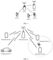
- FIG. 2 is a diagram of an architecture of a communication system according to an embodiment of this application.
- the communication system may include at least one network device and at least one terminal device, for example, a terminal device 1 to a terminal device 4 in FIG. 2 .
- the terminal device 3 and the terminal device 4 shown in FIG. 2 may directly communicate with each other.
- direct communication between the terminal devices may be implemented by using a D2D technology.
- the terminal device 1 to the terminal device 4 may separately communicate with the network device.
- the terminal device 3 and the terminal device 4 may directly communicate with the network device, or may indirectly communicate with the network device, for example, communicate with the network device via another terminal device (not shown in FIG. 2 ). It should be understood that FIG.
- the network device may alternatively be a communication apparatus or the like functioning as a base station in a non-terrestrial communication system, D2D, V2X, or M2M.
- a specific type of the network device is not limited in this embodiment of this application.
- names of communication apparatuses with network device functions may be different, and are not listed in this embodiment of this application.
- the network device may include a central unit (central unit, CU), a distributed unit (distributed unit, DU), and the like.
- a CU may be further divided into a CU-control plane (control plane, CP), a CU-user plane (user plane, UP), and the like.
- the network device may alternatively be an open radio access network (open radio access network, ORAN) architecture or the like.
- ORAN open radio access network
- a subcarrier grouping method for example, a plurality of adjacent subcarriers report one piece of CSI, to reduce feedback overheads of CSI reports.
- CSI of equally-spaced subcarriers is selected for transmission, and after a receive end receives a compressed CSI, the receive end performs initial CSI restoration.
- the method has an advantage of low calculation complexity.
- accuracy of this method is relatively low, which affects a subsequent application such as beamforming or Wi-Fi sensing, and cannot meet a CSI compression quality requirement.
- CSI feedback plays an important role in the radio frequency sensing field such as Wi-Fi positioning.
- different human behaviors introduce different multipath changes. Therefore, by observing human movement in a wireless sensor network and the resulting CSI, it is possible to reconstruct a real physical world through radio frequency sensing, thereby providing a wide range of new services.
- CSI compression can reduce a transmission latency by reducing an amount of data that needs to be transmitted, and improve timeliness of CSI feedback and wireless sensing.
- FIG. 4 is a schematic flowchart of a CSI processing method according to an embodiment of this application.
- the method may be applied to the communication system shown in FIG. 1 or FIG. 2 .
- the method may be applied to a transmit end and a receive end.
- the transmit end may be understood as a communication apparatus sending a CSI report
- the receive end may be understood as a communication apparatus receiving the CSI report.
- a STA may be used as a transmit end
- an AP may be used as a receive end.
- an AP may be used as a transmit end
- a STA may be used as a receive end.
- UE may be used as a transmit end
- a base station may be used as a receive end.
- a base station may be used as a transmit end, and UE may be used as a receive end.
- a beamforming receive end (beamformee) may be used as a transmit end, and a beamforming transmit end (beamformer) may be used as a receive end.
- the beamforming transmit end may be understood as a communication apparatus sending a pilot signal
- the beamforming receive end may be understood as a communication apparatus receiving the pilot signal.
- the beamforming receive end may obtain a channel measurement result based on the pilot signal sent by the beamforming transmit end, to feed back CSI.
- the pilot signal may be understood as a signal used for channel detection, or a signal used for channel estimation, or a signal used for channel measurement.
- channel detection, channel estimation, and channel measurement in this embodiment of this application are mutually interchangeable.
- transmit end and the receive end in this embodiment of this application refer to the foregoing descriptions of FIG. 1 and FIG. 2 . Details are not described herein again. Whether another forwarding apparatus is further included between the transmit end and the receive end is not limited in this embodiment of this application.
- the CSI processing method provided in this embodiment of this application relates to the following optimization problem: min x Ax ⁇ b 2 where a vector b represents a vector of uncompressed CSI, a vector x represents a vector of compressed CSI, and elements in the vector b and the vector x are complex numbers.
- a quantity of elements in the vector b is M
- a quantity of elements in the vector x is N, where both M and N are positive integers, and M > N.
- the vector b may be represented as b ⁇ C M ⁇ 1
- the vector x may be represented as x ⁇ C N ⁇ 1.
- a matrix A represents a transformation matrix used for CSI compression
- the matrix A is a complex matrix with M rows and N columns, and the matrix A may also be represented as A ⁇ C M ⁇ N .
- a quantity M of rows corresponds to a quantity of pieces of uncompressed CSI (which may also be understood as the quantity of elements in the vector b )
- a quantity N of columns corresponds to a quantity of pieces of compressed CSI (which may also be understood as the quantity of elements in the vector x ) .
- the compressed CSI shown herein is compressed CSI (for example, the vector x ) obtained by the transmit end based on the uncompressed CSI (for example, the vector b ), and that "compressed" in the accompanying drawings in embodiments of this application represents CSI restored by the receive end based on the vector x and the transformation matrix A , that is, Ax . Therefore, "compressed” in the accompanying drawings should not be understood as compressed CSI obtained by the transmit end based on the uncompressed CSI and the transformation matrix in embodiments of this application.
- the uncompressed CSI in this embodiment of this application may be understood as CSI obtained by the transmit end through channel estimation for a group of subcarriers between a transmit antenna and a receive antenna.
- the vector b may correspond to a vector of CSI obtained based on a transmit antenna, a receive antenna, and a group of subcarriers.
- a quantity of subcarriers specifically included in a group of subcarriers is not limited in this embodiment of this application.
- a group of subcarriers may include 64 subcarriers, 242 subcarriers, or the like, which is not listed one by one.
- M shown in this embodiment of this application may be understood as a quantity of pieces of CSI obtained on a group of subcarriers for a transmit antenna and a receive antenna.
- the transmit end may compress M pieces of CSI of a group of contiguous subcarriers to N pieces of CSI.
- M P represents a corresponding quantity of subcarriers when a minimum CSI compression performance requirement is met.
- M C represents a quantity of contiguous subcarriers within a bandwidth of 20 MHz, 40 MHz, 80 MHz, 160 MHz, or 320 MHz, or resource units (resource units, RUs) with different sizes.
- a direct current (direct current, DC) subcarrier which may also be referred to as a direct current subcarrier for short
- a center frequency within the bandwidth
- presence of the DC subcarrier may cause the M subcarriers shown in this embodiment of this application to be non-contiguous.
- the transmit end may perform interpolation processing at the DC position to obtain CSI of contiguous subcarriers within the bandwidth.
- the receive end may restore more than M pieces of CSI, and then the receive end removes the CSI at the DC position to obtain initial CSI.
- the transmit antenna shown in this embodiment of this application is an antenna configured to send a pilot signal (for example, an antenna configured to send a pilot signal at the receive end), and that the receive antenna is an antenna configured to receive the pilot signal (for example, an antenna configured to receive the pilot signal at the receive end).
- the foregoing formula (1) may be understood as a two-norm minimization problem, which belongs to a convex optimization problem. Therefore, a result of the optimization problem can be solved by using a convex optimization algorithm, and a vector x of compressed CSI is obtained.
- the receive end may multiply each column of the matrix A by corresponding elements of the compressed CSI, and then obtain a cumulative sum, to implement estimation of the uncompressed CSI.
- an approximate sign is used in formula (2) because the CSI restored by the receive end based on the compressed CSI and the matrix A may be different from the uncompressed CSI obtained by the transmit end.
- the difference may be caused by the optimization problem in formula (1).
- the vector x obtained by the transmit end may not make ⁇ Ax - b ⁇ 2 equal to 0.
- the difference may be caused by an error in quantization and encoding. Examples are not listed one by one herein.
- modulus values (which may also be referred to as values) of the uncompressed CSI vary slowly, that is, the uncompressed CSI has similar (or approximate) modulus values.
- Modulus values in the vector b are similar (or approximate). Therefore, by setting the modulus values of the elements in the vector A to be the same and all to 1, it is possible to effectively adjust the modulus values of the elements in the vector x to achieve similarity (or approximation) between modulus values of elements in the vector Ax and those in the vector b . Therefore, calculation complexity in optimization of formula (1) by the transmit end can be effectively reduced, the difference between the CSI restored by the receive end and the uncompressed CSI is minimized, and compression performance of CSI compression is improved.
- Condition 2 Angles (which may also be understood as phases) of elements in at least one column in the matrix A vary periodically, and angles of elements in different columns vary with different periods.
- FIG. 5a is a diagram of phase variations of CSI according to an embodiment of this application.
- a horizontal coordinate represents a subcarrier sequence number
- a vertical coordinate represents a phase
- a unit is ⁇ .
- FIG. 5a is a diagram of phase variations of CSI shown by using an example in which a group of subcarriers is 242 subcarriers and corresponds to one transmit antenna and one receive antenna.
- a subcarrier quantity and an antenna quantity shown in FIG. 5a should not be understood as a limitation on this embodiment of this application.
- the phase variations of the CSI shown in FIG. 5a are general. It may be understood that the angles and phases in this embodiment of this application may be understood as equivalent.
- angles of the elements in the vector b have different frequency components, that is, periodic angle variations of the vector b are not completely regular (which may also be understood as not precisely periodic variations). Therefore, angles of elements in different columns in the matrix A correspond to different periods, so that an angle variation rule (which may also be referred to as a phase characteristic) of the uncompressed CSI can be effectively matched, thereby improving accuracy of CSI compression. Therefore, the difference between the CSI restored by the receive end and the uncompressed CSI is minimized, and it is ensured as much as possible that the receive end can restore the uncompressed CSI based on the compressed CSI and the transformation matrix.
- the condition 2 may be extended to each column in the matrix A.
- angles of elements in each column in the matrix A vary periodically.
- the condition 2 may also be represented as follows: Angular velocities of angles of elements in at least one column in the matrix A remain unchanged (a constant angular velocity may also be understood as a same angular velocity), and angular velocities of angles of elements in different columns are different. If the condition 2 is extended to each column in the matrix A, angular velocities of angles of elements in each column in the matrix A remain unchanged, and angular velocities of angles of elements in different columns are different.
- Angles of elements in the matrix A may be determined based on M, N, and a phase period of the uncompressed CSI.
- 2 ⁇ T 0 ⁇ k n may be equivalent to an angular velocity. Adjusting an angular velocity of an element by using the variable n may better combine formula (4) with a column in the matrix A , so that angles of elements in different columns in the matrix A have different angular velocities, thereby improving accuracy of CSI compression.
- T 0 may be understood as a quantity of subcarriers included in a 2 ⁇ phase variation of the uncompressed CSI.
- T 0 may be understood as a minimum period of the phase variation of the uncompressed CSI.
- T 0 may be understood as a reference period.
- T 0 may be understood as an optimal period of an optimization problem shown in formula (5).
- T 0 is related to an angle of the uncompressed CSI.
- T 0 argmin T 0 Ax ⁇ b 2
- condition 3 may also be understood as angles of elements in the matrix A may be determined based on M, N, and frequency components of a DFT of the phases of the uncompressed CSI.
- FIG. 5b is a diagram of frequency components of a DFT of phases of CSI according to an embodiment of this application.
- a horizontal coordinate represents a frequency component
- a vertical coordinate represents a modulus value of a coefficient (which may also be referred to as a weight) corresponding to the frequency component.
- a coefficient corresponding to a frequency component after the DFT is a complex number
- the vertical coordinate shown in FIG. 5b represents a modulus value of the coefficient.
- the horizontal coordinate in FIG. 5b may also be understood as a quantity of periods in which the phases of the uncompressed CSI (vector b ) vary, and the quantity of periods may correspond to a quantity of oblique lines in FIG. 5a .
- )) represents a frequency component corresponding to the foregoing maximum value, or a horizontal coordinate corresponding to the foregoing highest point, or a frequency component corresponding to the foregoing maximum weight.
- )) - 1 represents a frequency component of a phase of the uncompressed CSI.
- T 0 may be obtained based on M and f 0 .
- Numerators in formula (7) and formula (8) are determined based on the quantity of elements in the uncompressed CSI. It may be understood that numerators in formula (9) and formula (10) are determined based on a length of the uncompressed CSI.
- T 0 may meet the following formula: M f 0 + 1 ⁇ T 0 ⁇ M f 0 ⁇ 1
- )) - 1 calculated by using the DFT is an integer, and a phase variation frequency of the uncompressed CSI may actually have a decimal place. Therefore, by searching for T 0 within the foregoing range by using formula (11), T 0 that optimizes formula (5) may be obtained.
- f 0 may meet the following formula: index max DFT ⁇ b ⁇ 2 ⁇ f 0 ⁇ index max DFT ⁇ b ⁇ 1
- T 0 and f 0 shown in this embodiment of this application may be combined with each other.
- formula (6) may be combined with formula (13) or formula (14).
- formula (12) may be combined with any one of formula (7) to formula (10).
- formula (14) may be combined with any one of formula (7) to formula (10). Examples are not listed one by one.
- an actual time domain sampling position may shift leftward, which is represented as a phase shift -
- ⁇ is not limited in this embodiment of this application. Therefore, in this embodiment of this application, k ( n ) ⁇ 0, ⁇ n ⁇ ⁇ 1, ..., N ⁇ .
- N rotation factors whose periods are respectively ⁇ , 2T 0 (1/2* f 0 ), 3/2T(2/3* f 0 ), 4/3T(3/4* f 0 ), ..., N/(N-1)T(1-N/N* f 0 ) may be constructed.
- the rotation factor may be understood as an angle variation with a constant modulus value.
- the method for compressing CSI based on the matrix A shown in this embodiment of this application may also be referred to as a CSI compression method based on a modified DFT matrix.
- FIG. 6 is a diagram of performance of a CSI compression method based on a regression polynomial method according to an embodiment of this application.
- "uncompressed” represents the uncompressed CSI (that is, the vector b )
- “compressed” represents the CSI (that is, Ax ) restored by the receive end based on the compressed CSI received by the receive end. It can be learned from FIG.
- compressed CSI obtained by using the CSI compression method based on the regression polynomial method causes an obvious deviation between the CSI restored by the receive end and the uncompressed CSI obtained by the transmit end.
- the matrix A in this embodiment of this application is a complex matrix, and the matrix A effectively uses phase continuity and periodicity of the uncompressed CSI, thereby effectively improving accuracy of CSI compression.
- the matrix B all elements in a first row are 1, and an element in a last row and a last column is M N .
- M N As M and N increase, M N >> 1 in the matrix B causes complexity and an error in solving the optimization problem to increase.
- modulus values of all elements in the matrix A are 1. Therefore, calculation complexity of the optimization problem is effectively reduced, and optimization estimation is implemented with high efficiency and low complexity.
- the method includes the following steps.
- a transmit end determines a CSI report.
- the CSI report includes first CSI, the first CSI is obtained based on second CSI and a transformation matrix, the transformation matrix is a complex matrix with M rows and N columns, modulus values of elements in the transformation matrix are 1, M is greater than N, M is a quantity of elements in the second CSI, and N is a quantity of elements in the first CSI.
- That a transmit end determines a CSI report may also be understood as: the transmit end generates the CSI report; or the transmit end performs CSI compression based on a channel detection result (or a channel estimation result), compresses a quantity of pieces of CSI from M to N, and obtains the CSI report based on compressed CSI; or the transmit end performs channel detection based on a reference signal to obtain M pieces of CSI, compresses the M pieces of CSI to N pieces of CSI by using a CSI compression method based on a modified DFT matrix, and obtains the CSI report based on the N pieces of CSI.
- the reference signal is a signal used for channel detection.
- the reference signal may be sent by a receive end to the transmit end, or the like.
- a source of the reference signal is not limited in this embodiment of this application.
- uncompressed CSI shown in this embodiment of this application includes M pieces of CSI.
- the M pieces of CSI may be CSI obtained by the transmit end based on M contiguous subcarriers between a transmit antenna and a receive antenna.
- the M pieces of CSI may be CSI obtained by the transmit end based on more than M contiguous subcarriers between a transmit antenna and a receive antenna.
- the transmit end may obtain more than M pieces of CSI, and then select M pieces of CSI for feedback.
- a procedure in which the transmit end compresses the CSI may be specifically as follows:
- the CSI restored by the receive end based on the transformation matrix and the first CSI is different from the second CSI (for example, the vector b shown above).
- the difference may be caused by the optimization problem in formula (1).
- the vector x obtained by the transmit end may not make ⁇ Ax - b ⁇ 2 equal to 0.
- the difference may be caused by an error in quantization and encoding. Examples are not listed one by one herein.
- the CSI restored by the receive end based on the transformation matrix and the first CSI may also be understood as "compressed" in the accompanying drawings in the embodiments of this application.
- formula (23) may be considered as a weighted sum of elements e j 2 ⁇ T 0 m 1 n ⁇ 1 at a same position in each periodic sequence, which can approach and approximate elements b ( m ) at a same position in an uncompressed CSI sequence. Therefore, the receive end can better approach and approximate the uncompressed CSI such as b (m).
- the transmit end performs CSI compression based on a channel detection result to compress a quantity of CSI from every M to N. Then the transmit end feeds back a compressed CSI vector x and compression parameters M, N, and T 0 .
- the receive end constructs a transformation matrix A based on the compression parameters M, N, and T 0 , and multiplies the constructed matrix A by the received compressed CSI vector x , as an estimation result of an actual CSI vector b .
- formula (24) is merely an example.
- the transformation matrix A may be extended to any dimension. Specific forms of the transformation matrix are not listed one by one in this embodiment of this application.
- all elements in a first row in the transformation matrix may be equal.
- all elements in a first column in the transformation matrix are equal, and all the elements in the first row in the transformation matrix are equal.
- a 6 ⁇ 3 e j 0 e j 0 e j 0 e j 0 e j 0 e j 0 e ⁇ j ⁇ T ⁇ 1 e ⁇ j 4 ⁇ 3 T ⁇ 1 e j 0 e ⁇ j ⁇ T ⁇ 2 e ⁇ j 4 ⁇ 3 T ⁇ 2 e j 0 e ⁇ j ⁇ T ⁇ 3 e ⁇ j 4 ⁇ 3 T ⁇ 3 e j 0 e ⁇ j ⁇ T ⁇ 4
- formula (25) is merely an example.
- all elements in a last row in the transformation matrix may be equal. Examples are not listed one by one herein.
- all variations of the transformation matrix fall within the protection scope of embodiments of this application.
- setting all elements in at least one column in the transformation matrix to be the same, or setting all elements in at least one row in the transformation matrix to be the same, or setting at least two columns in the transformation matrix to be the same, or setting at least two rows in the transformation matrix to be the same is a variation of the transformation matrix.
- performing column permutation, row permutation, and the like on the transformation matrix also belongs to variations of the transformation matrix. The variations of the transformation matrix are not listed one by one.
- CSI vector b [0.451378116153413 + 0.161206470054790j, 0.483619410164371 + 0.0322412940109581j, 0.515860704175329 - 0.0322412940109581j, 0.548101998186287 - 0.0967238820328741j, 0.548101998186287 - 0.161206470054790j, 0.515860704175329 - 0.225689058076706j, 0.515860704175329 - 0.290171646098622j, 0.483619410164371 - 0.322412940109581j, 0.419136822142455 - 0.386895528131497j, 0.354654234120539 - 0.419136822142455j, 0.290171646098622 - 0.451378116153413j, 0.225
- the receive end may obtain M, N, and T 0 (or f 0 ) based on the CSI report received in step 402.
- the receive end may obtain M, N, and f 0 (or T 0 ) based on a CSI report including M, N, and f 0 (or T 0 ) before the CSI report received in step 402.
- the receive end may obtain f 0 or T 0 based on a CSI report including f 0 or T 0 before the CSI report received in step 402, and obtain M and N based on the CSI report received in step 402.
- the receive end may obtain, based on the indication information, a compression method used when the transmit end performs CSI compression, to process the first CSI in the CSI report based on the corresponding compression method.
- the transmit end compresses the second CSI by using the transformation matrix, to obtain the first CSI, where a quantity of rows in the transformation matrix corresponds to the quantity of elements in the second CSI (which may also be understood as the uncompressed CSI), and a quantity of columns in the transformation matrix corresponds to the quantity of elements in the first CSI (which may also be understood as the compressed CSI).
- a quantity of rows in the transformation matrix corresponds to the quantity of elements in the second CSI (which may also be understood as the uncompressed CSI)
- a quantity of columns in the transformation matrix corresponds to the quantity of elements in the first CSI (which may also be understood as the compressed CSI).
- M is greater than N
- overheads occupied by the compressed CSI are less than overheads occupied by the uncompressed CSI. Therefore, CSI feedback overheads can be effectively reduced.
- this embodiment of this application may be further applied to different M and N, to implement a relatively long compression length and meet massive MIMO and multi-subcarrier scenarios.
- modulus values of the uncompressed CSI vary slowly, that is, the uncompressed CSI has similar (or approximate) modulus values. Therefore, by setting the modulus values of the elements in the transformation matrix to be the same and all to 1, it is possible to ensure that modulus values of elements in restored CSI are also similar (or approximate) when the receive end restores the CSI based on the compressed CSI and the transformation matrix. Therefore, accuracy of the CSI restored by the receive end is ensured, and compression performance of CSI compression is improved.
- CSI of a group of subcarriers on a pair of transmit and receive antennas is considered. Normalization processing is performed on each group of CSI, that is, each piece of CSI is divided by a maximum modulus value of a plurality of pieces of CSI in the group.
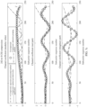
- FIG. 7a to FIG. 7c respectively show performance comparison at different compression rates.
- Subcarrier grouping method CSI data is not sent for every subcarrier. Instead, CSI of multiple subcarriers of each antenna is grouped, and only one piece of CSI is transmitted for each group.
- Regression polynomial method It is a CSI compression method based on a regression polynomial matrix and a mathematical model of two-norm minimization.
- FIG. 7a shows compression performance when CSI of a group of 32 subcarriers is compressed to 8 pieces of CSI in different methods. It can be learned from FIG. 7a that an obvious error occurs at a boundary point in the subcarrier grouping method and the regression polynomial method.
- the subcarrier grouping method in an actual application, two to four subcarriers are generally grouped into a group to ensure compression quality. As a compression rate increases, the compression quality obviously decreases.
- the regression polynomial method increases the CSI compression rate at the cost of higher complexity.
- the CSI compression method based on a modified DFT matrix according to this embodiment of this application is effectively combined with a phase variation characteristic of uncompressed CSI, and therefore effectively improves compression performance of CSI compression. Even if the compression rate is increased, accuracy of CSI compression can still be ensured by using the method provided in this embodiment of this application.
- FIG. 7c shows compression performance when CSI of a group of 242 subcarriers is compressed to 8 pieces of CSI in different methods. It can be learned from FIG. 7b that a relatively large error also occurs in the regression polynomial method, and a compression quality requirement cannot be met.
- the CSI compression method based on a modified DFT matrix according to this embodiment of this application is effectively combined with an angle variation rule of the uncompressed CSI, and therefore can always meet compression quality and have better CSI compression performance.
- the CSI compression method based on a modified DFT matrix according to this embodiment of this application is applicable to different compression rates, and CSI compression performance can be ensured for any compression rate.
- FIG. 8a and FIG. 8b respectively show comparison of average performance of compression methods in a laboratory empty room environment and a simulator environment, taking 10,000 groups of channel data samples into account, where each group of channel data samples may include a group of CSI.
- a mean square error mean squared error (mean squared error, MSE) between the CSI restored by the receive end and uncompressed CSI data is used as a performance indicator for comparison.
- MSE mean squared error
- MSE 1/ M * ⁇ Ax - b ⁇ 2 .
- the method provided in this embodiment of this application effectively reduces an error by about 7 dB.
- a compression quality threshold is set to -15 dB.
- the subcarrier grouping method can meet the quality requirement in 64-to-8 compression
- the regression polynomial method can meet the quality requirement in 128-to-8 compression
- the method provided in this embodiment of this application can meet the quality requirement in 242-to-8 compression.
- the regression polynomial method can meet the quality requirement in 64-to-8 compression
- the method provided in this embodiment of this application can meet the quality requirement in 128-to-8 compression. Therefore, according to the method provided in this embodiment of this application, the compression rate is increased. For any compression length, the method provided in this embodiment of this application has a smaller mean square error. Therefore, the error is effectively reduced, and compression accuracy is improved.
- a communication apparatus provided in an embodiment of this application is described below.
- the communication apparatus is divided into functional modules based on the foregoing method embodiments.
- the functional modules may be obtained through division in a one-to-one correspondence with the functions, or two or more functions may be integrated into one processing module.
- the integrated module may be implemented in a form of hardware, or may be implemented in a form of a software functional module. It should be noted that division of the modules in this application is an example. The division is merely logical function division and may be other division in an actual implementation. The following describes in detail communication apparatuses in embodiments of this application with reference to FIG. 9 to FIG. 11 .
- FIG. 9 is a diagram of a structure of a communication apparatus according to an embodiment of this application.
- the communication apparatus includes a processing unit 901 and a transceiver unit 902.
- processing unit 901 may be configured to determine the CSI report and output the CSI report, so that the transceiver unit 902 sends the CSI report.
- the communication apparatus may be configured to perform the steps, the functions, or the like performed by the transmit end in the foregoing method embodiments (including FIG. 4 ).
- the communication apparatus may further include a memory.
- the memory may be configured to store at least one of formula (1) to formula (25).
- the communication apparatus may be configured to perform the steps, the functions, or the like performed by the receive end in the foregoing method embodiments (including FIG. 4 ).
- the logic circuit 1101 is specifically configured to: determine the transformation matrix based on T 0 or f 0 , and M and N; and process the first CSI based on the transformation matrix to obtain the second CSI.
- the communication apparatus may further include a memory.
- the memory may be configured to store at least one of formula (1) to formula (25).
- An embodiment of this application further provides a wireless communication system.
- the wireless communication system includes a transmit end and a receive end.
- the transmit end and the receive end may be configured to perform the method in any one of the foregoing embodiments (as shown in FIG. 4 ).
- this application further provides a computer program.
- the computer program is used to implement operations and/or processing performed by the transmit end in the methods provided in this application.
- This application further provides a computer program.
- the computer program is used to implement operations and/or processing performed by the receive end in the methods provided in this application.
- This application further provides a computer-readable storage medium.
- the computer-readable storage medium stores computer code.
- the computer code When the computer code is run on a computer, the computer is enabled to perform operations and/or processing performed by the receive end in the methods provided in this application.
- the computer program product includes computer code or a computer program.
- the computer code or the computer program is run on a computer, operations and/or processing performed by the receive end in the methods provided in this application are/is performed.
- the disclosed system, apparatus, and method may be implemented in other manners.
- the foregoing apparatus embodiments are merely examples.
- division of the units is merely logical function division and may be other division in an actual implementation.
- a plurality of units or components may be combined or integrated into another system, or some features may be ignored or not performed.
- the displayed or discussed mutual couplings or direct couplings or communication connections may be implemented by using some interfaces.
- the indirect couplings or communication connections between the apparatuses or units may be implemented in electronic, mechanical, or other forms.
- the units described as separate parts may or may not be physically separate, and parts displayed as units may or may not be physical units, and may be located in one position, or may be distributed on a plurality of network units. Some or all of the units may be selected based on an actual requirement, to achieve technical effects of the solutions provided in embodiments of this application.
- functional units in embodiments of this application may be integrated into one processing unit, each of the units may exist alone physically, or two or more units are integrated into one unit.
- the integrated unit may be implemented in a form of hardware, or may be implemented in a form of a software functional unit.
- the integrated unit When the integrated unit is implemented in the form of a software functional unit and sold or used as an independent product, the integrated unit may be stored in a computer-readable storage medium. Based on such an understanding, the technical solutions of this application essentially, or the part contributing to the conventional technology, or all or some of the technical solutions may be implemented in a form of a software product.
- the computer software product is stored in a readable storage medium and includes a plurality of instructions for instructing a computer device (which may be a personal computer, a server, or a network device) to perform all or some of the steps of the methods described in embodiments of this application.
- the readable storage medium includes any medium that can store program code, for example, a USB flash drive, a removable hard disk, a read-only memory (read-only memory, ROM), a random access memory (random access memory, RAM), a magnetic disk, or an optical disc.
- program code for example, a USB flash drive, a removable hard disk, a read-only memory (read-only memory, ROM), a random access memory (random access memory, RAM), a magnetic disk, or an optical disc.
Landscapes
- Engineering & Computer Science (AREA)
- Computer Networks & Wireless Communication (AREA)
- Signal Processing (AREA)
- Physics & Mathematics (AREA)
- Mathematical Physics (AREA)
- Quality & Reliability (AREA)
- Discrete Mathematics (AREA)
- General Physics & Mathematics (AREA)
- Mobile Radio Communication Systems (AREA)
Applications Claiming Priority (2)
| Application Number | Priority Date | Filing Date | Title |
|---|---|---|---|
| CN202211104120.7A CN117728869A (zh) | 2022-09-09 | 2022-09-09 | 信道状态信息的处理方法和装置 |
| PCT/CN2023/117738 WO2024051821A1 (fr) | 2022-09-09 | 2023-09-08 | Procédé et appareil de traitemement d'informations csi |
Publications (2)
| Publication Number | Publication Date |
|---|---|
| EP4580080A1 true EP4580080A1 (fr) | 2025-07-02 |
| EP4580080A4 EP4580080A4 (fr) | 2025-12-24 |
Family
ID=90192082
Family Applications (1)
| Application Number | Title | Priority Date | Filing Date |
|---|---|---|---|
| EP23862515.6A Pending EP4580080A4 (fr) | 2022-09-09 | 2023-09-08 | Procédé et appareil de traitemement d'informations csi |
Country Status (7)
| Country | Link |
|---|---|
| US (1) | US20250211307A1 (fr) |
| EP (1) | EP4580080A4 (fr) |
| JP (1) | JP2025531810A (fr) |
| KR (1) | KR20250059516A (fr) |
| CN (1) | CN117728869A (fr) |
| TW (1) | TW202418787A (fr) |
| WO (1) | WO2024051821A1 (fr) |
Families Citing this family (2)
| Publication number | Priority date | Publication date | Assignee | Title |
|---|---|---|---|---|
| US20240364407A1 (en) * | 2023-04-27 | 2024-10-31 | Qualcomm Incorporated | Layer 2 signaling of a compressed channel state information report |
| CN120958866A (zh) * | 2024-05-30 | 2025-11-14 | 北京小米移动软件有限公司 | 数据处理方法、第一设备、第二设备以及系统 |
Family Cites Families (9)
| Publication number | Priority date | Publication date | Assignee | Title |
|---|---|---|---|---|
| KR101680212B1 (ko) * | 2011-07-18 | 2016-11-28 | 주식회사 케이티 | 단말의 채널 상태 정보 전송 방법, 그 단말, 전송단의 채널 상태 정보 수신 방법, 및 그 전송단 |
| CN106470173A (zh) * | 2015-08-17 | 2017-03-01 | 上海无线通信研究中心 | 一种bbu-rru数据压缩方法 |
| CN106788875A (zh) * | 2015-11-18 | 2017-05-31 | 电信科学技术研究院 | 一种信道状态信息反馈方法及装置 |
| WO2020069459A1 (fr) * | 2018-09-28 | 2020-04-02 | Nokia Technologies Oy | Compression et quantification orthogonale conjointe pour rétroaction d'informations d'état de canal de type ii |
| WO2020150700A1 (fr) * | 2019-01-18 | 2020-07-23 | Apple Inc. | Compression d'informations d'état de canal (csi) dans le domaine fréquentiel |
| CA3130222C (fr) * | 2019-02-15 | 2024-03-12 | Zte Corporation | Retroaction d'informations d'etat de canal dans une communication sans fil |
| EP3935742A4 (fr) * | 2019-03-06 | 2022-10-19 | Telefonaktiebolaget LM Ericsson (publ) | Compression et décompression d'estimations de canal de liaison descendante |
| WO2021046783A1 (fr) * | 2019-09-11 | 2021-03-18 | Nokia Shanghai Bell Co., Ltd. | Retour d'informations d'état de canal |
| CN114079493A (zh) * | 2020-08-13 | 2022-02-22 | 华为技术有限公司 | 一种信道状态信息测量反馈方法及相关装置 |
-
2022
- 2022-09-09 CN CN202211104120.7A patent/CN117728869A/zh active Pending
-
2023
- 2023-09-05 TW TW112133657A patent/TW202418787A/zh unknown
- 2023-09-08 WO PCT/CN2023/117738 patent/WO2024051821A1/fr not_active Ceased
- 2023-09-08 JP JP2025514292A patent/JP2025531810A/ja active Pending
- 2023-09-08 KR KR1020257011168A patent/KR20250059516A/ko active Pending
- 2023-09-08 EP EP23862515.6A patent/EP4580080A4/fr active Pending
-
2025
- 2025-03-07 US US19/074,165 patent/US20250211307A1/en active Pending
Also Published As
| Publication number | Publication date |
|---|---|
| WO2024051821A1 (fr) | 2024-03-14 |
| CN117728869A (zh) | 2024-03-19 |
| TW202418787A (zh) | 2024-05-01 |
| JP2025531810A (ja) | 2025-09-25 |
| KR20250059516A (ko) | 2025-05-02 |
| US20250211307A1 (en) | 2025-06-26 |
| EP4580080A4 (fr) | 2025-12-24 |
Similar Documents
| Publication | Publication Date | Title |
|---|---|---|
| US20250211307A1 (en) | Channel state information processing method and apparatus | |
| US20240204839A1 (en) | Beamforming report feedback method and apparatus | |
| US9843962B2 (en) | Dual-stream signal (SIG) field encoding with higher order modulation | |
| US20190123991A1 (en) | Systems and Methods for a Sounding Frame in an IEEE 802.11AX Compliant Network | |
| CN116264591A (zh) | 信号处理方法及装置 | |
| JP2025541175A (ja) | サウンディングにおける追加ltfのための通信装置および通信方法 | |
| US20260019208A1 (en) | Communication method and apparatus based on ppdu | |
| CN114586435B (zh) | 信道状态信息上报方法、基站和用户设备 | |
| US20250323695A1 (en) | Antenna pairing method and apparatus | |
| US20240195552A1 (en) | Ndpa frame transmission method and related apparatus | |
| CN116707591A (zh) | 一种天线模式切换方法及相关装置 | |
| US20240381144A1 (en) | Channel sounding method and apparatus | |
| EP4529032A1 (fr) | Procédé de mesure de positionnement et dispositif de communication | |
| US20260019214A1 (en) | Wireless Communication Method and Communication Device | |
| US20260088954A1 (en) | Communication method, communication apparatus, and communication system | |
| EP4686109A1 (fr) | Procédé de communication et appareil de communication | |
| US20260122534A1 (en) | Ppdu transmission method and apparatus | |
| WO2026012192A1 (fr) | Procédé et appareil de communication basés sur une adaptation de liaison | |
| WO2024109541A1 (fr) | Procédé et appareil de transmission de multidiffusion dans un réseau sans fil et support de stockage lisible | |
| CN120343722A (zh) | 通信方法、装置及可读存储介质 | |
| WO2025036371A1 (fr) | Procédé et appareil de communication de détection | |
| WO2026037050A1 (fr) | Procédé et appareil de mesure | |
| CN121604118A (zh) | 通信方法及装置 | |
| WO2026037198A1 (fr) | Procédé et appareil de communication | |
| CN120343721A (zh) | 通信方法、装置及可读存储介质 |
Legal Events
| Date | Code | Title | Description |
|---|---|---|---|
| STAA | Information on the status of an ep patent application or granted ep patent |
Free format text: STATUS: THE INTERNATIONAL PUBLICATION HAS BEEN MADE |
|
| PUAI | Public reference made under article 153(3) epc to a published international application that has entered the european phase |
Free format text: ORIGINAL CODE: 0009012 |
|
| STAA | Information on the status of an ep patent application or granted ep patent |
Free format text: STATUS: REQUEST FOR EXAMINATION WAS MADE |
|
| 17P | Request for examination filed |
Effective date: 20250324 |
|
| AK | Designated contracting states |
Kind code of ref document: A1 Designated state(s): AL AT BE BG CH CY CZ DE DK EE ES FI FR GB GR HR HU IE IS IT LI LT LU LV MC ME MK MT NL NO PL PT RO RS SE SI SK SM TR |
|
| DAV | Request for validation of the european patent (deleted) | ||
| DAX | Request for extension of the european patent (deleted) | ||
| A4 | Supplementary search report drawn up and despatched |
Effective date: 20251124 |
|
| RIC1 | Information provided on ipc code assigned before grant |
Ipc: H04B 7/06 20060101AFI20251118BHEP Ipc: H04L 1/00 20060101ALI20251118BHEP |