EP4580081A1 - Verfahren und vorrichtung zur auswahl eines antennenmodus für vollduplexkommunikation in einem drahtloskommunikationssystem - Google Patents
Verfahren und vorrichtung zur auswahl eines antennenmodus für vollduplexkommunikation in einem drahtloskommunikationssystem Download PDFInfo
- Publication number
- EP4580081A1 EP4580081A1 EP23873246.5A EP23873246A EP4580081A1 EP 4580081 A1 EP4580081 A1 EP 4580081A1 EP 23873246 A EP23873246 A EP 23873246A EP 4580081 A1 EP4580081 A1 EP 4580081A1
- Authority
- EP
- European Patent Office
- Prior art keywords
- symbol
- base station
- sbfd
- downlink
- uplink
- Prior art date
- Legal status (The legal status is an assumption and is not a legal conclusion. Google has not performed a legal analysis and makes no representation as to the accuracy of the status listed.)
- Pending
Links
Images






Classifications
-
- H—ELECTRICITY
- H04—ELECTRIC COMMUNICATION TECHNIQUE
- H04L—TRANSMISSION OF DIGITAL INFORMATION, e.g. TELEGRAPHIC COMMUNICATION
- H04L5/00—Arrangements affording multiple use of the transmission path
- H04L5/0001—Arrangements for dividing the transmission path
- H04L5/0026—Division using four or more dimensions, e.g. beam steering or quasi-co-location [QCL]
-
- H—ELECTRICITY
- H04—ELECTRIC COMMUNICATION TECHNIQUE
- H04B—TRANSMISSION
- H04B7/00—Radio transmission systems, i.e. using radiation field
- H04B7/02—Diversity systems; Multi-antenna system, i.e. transmission or reception using multiple antennas
- H04B7/04—Diversity systems; Multi-antenna system, i.e. transmission or reception using multiple antennas using two or more spaced independent antennas
- H04B7/06—Diversity systems; Multi-antenna system, i.e. transmission or reception using multiple antennas using two or more spaced independent antennas at the transmitting station
- H04B7/0602—Diversity systems; Multi-antenna system, i.e. transmission or reception using multiple antennas using two or more spaced independent antennas at the transmitting station using antenna switching
- H04B7/0608—Antenna selection according to transmission parameters
-
- H—ELECTRICITY
- H04—ELECTRIC COMMUNICATION TECHNIQUE
- H04B—TRANSMISSION
- H04B7/00—Radio transmission systems, i.e. using radiation field
- H04B7/02—Diversity systems; Multi-antenna system, i.e. transmission or reception using multiple antennas
- H04B7/04—Diversity systems; Multi-antenna system, i.e. transmission or reception using multiple antennas using two or more spaced independent antennas
- H04B7/06—Diversity systems; Multi-antenna system, i.e. transmission or reception using multiple antennas using two or more spaced independent antennas at the transmitting station
- H04B7/0686—Hybrid systems, i.e. switching and simultaneous transmission
- H04B7/0691—Hybrid systems, i.e. switching and simultaneous transmission using subgroups of transmit antennas
-
- H—ELECTRICITY
- H04—ELECTRIC COMMUNICATION TECHNIQUE
- H04B—TRANSMISSION
- H04B7/00—Radio transmission systems, i.e. using radiation field
- H04B7/02—Diversity systems; Multi-antenna system, i.e. transmission or reception using multiple antennas
- H04B7/04—Diversity systems; Multi-antenna system, i.e. transmission or reception using multiple antennas using two or more spaced independent antennas
- H04B7/06—Diversity systems; Multi-antenna system, i.e. transmission or reception using multiple antennas using two or more spaced independent antennas at the transmitting station
- H04B7/0686—Hybrid systems, i.e. switching and simultaneous transmission
- H04B7/0695—Hybrid systems, i.e. switching and simultaneous transmission using beam selection
- H04B7/06952—Selecting one or more beams from a plurality of beams, e.g. beam training, management or sweeping
- H04B7/06968—Selecting one or more beams from a plurality of beams, e.g. beam training, management or sweeping using quasi-colocation [QCL] between signals
-
- H—ELECTRICITY
- H04—ELECTRIC COMMUNICATION TECHNIQUE
- H04B—TRANSMISSION
- H04B7/00—Radio transmission systems, i.e. using radiation field
- H04B7/02—Diversity systems; Multi-antenna system, i.e. transmission or reception using multiple antennas
- H04B7/04—Diversity systems; Multi-antenna system, i.e. transmission or reception using multiple antennas using two or more spaced independent antennas
- H04B7/08—Diversity systems; Multi-antenna system, i.e. transmission or reception using multiple antennas using two or more spaced independent antennas at the receiving station
- H04B7/0802—Diversity systems; Multi-antenna system, i.e. transmission or reception using multiple antennas using two or more spaced independent antennas at the receiving station using antenna selection
- H04B7/0822—Diversity systems; Multi-antenna system, i.e. transmission or reception using multiple antennas using two or more spaced independent antennas at the receiving station using antenna selection according to predefined selection scheme
-
- H—ELECTRICITY
- H04—ELECTRIC COMMUNICATION TECHNIQUE
- H04B—TRANSMISSION
- H04B7/00—Radio transmission systems, i.e. using radiation field
- H04B7/02—Diversity systems; Multi-antenna system, i.e. transmission or reception using multiple antennas
- H04B7/04—Diversity systems; Multi-antenna system, i.e. transmission or reception using multiple antennas using two or more spaced independent antennas
- H04B7/08—Diversity systems; Multi-antenna system, i.e. transmission or reception using multiple antennas using two or more spaced independent antennas at the receiving station
- H04B7/0868—Hybrid systems, i.e. switching and combining
- H04B7/0874—Hybrid systems, i.e. switching and combining using subgroups of receive antennas
-
- H—ELECTRICITY
- H04—ELECTRIC COMMUNICATION TECHNIQUE
- H04L—TRANSMISSION OF DIGITAL INFORMATION, e.g. TELEGRAPHIC COMMUNICATION
- H04L5/00—Arrangements affording multiple use of the transmission path
- H04L5/0091—Signalling for the administration of the divided path, e.g. signalling of configuration information
- H04L5/0094—Indication of how sub-channels of the path are allocated
-
- H—ELECTRICITY
- H04—ELECTRIC COMMUNICATION TECHNIQUE
- H04L—TRANSMISSION OF DIGITAL INFORMATION, e.g. TELEGRAPHIC COMMUNICATION
- H04L5/00—Arrangements affording multiple use of the transmission path
- H04L5/14—Two-way operation using the same type of signal, i.e. duplex
-
- H—ELECTRICITY
- H04—ELECTRIC COMMUNICATION TECHNIQUE
- H04W—WIRELESS COMMUNICATION NETWORKS
- H04W88/00—Devices specially adapted for wireless communication networks, e.g. terminals, base stations or access point devices
- H04W88/08—Access point devices
Definitions
- V2X vehicle-to-everything
- NR-U new radio unlicensed
- NTN non-terrestrial network
- 5G baseline architecture e.g., service based architecture, service based interface
- NFV network functions virtualization
- SDN software-defined networking
- MEC mobile edge computing
- the disclosed embodiment provides a device and method capable of effectively providing a service in a mobile communication system.
- a method performed by a base station of a communication system may include transmitting first beam related configuration information to a terminal; identifying a beam related configuration for each symbol according to the first beam related configuration information; transmitting a downlink in a first symbol based on a beam related configuration related to the first symbol; and receiving an uplink in a second symbol based on a beam related configuration related to the second symbol, wherein the first symbol may be configured to correspond to a downlink symbol or a subband non-overlapping full duplex (SBFD) symbol, the second symbol may be configured to correspond to an uplink symbol or the SBFD symbol, and the first beam related configuration information may include at least one of a first beam related configuration corresponding to an antenna panel of the base station related to the downlink symbol, a second beam related configuration corresponding to an antenna panel of the base station related to the uplink symbol, or a third beam related configuration corresponding to an antenna panel of the base station related to the SBFD symbol.
- SBFD subband non-overlapping full duplex
- a base station of a communication system may include a transceiver; and a controller, wherein the controller may be configured to transmit first beam related configuration information to a terminal, to identify a beam related configuration for each symbol according to the first beam related configuration information, to transmit a downlink in a first symbol based on a beam related configuration related to the first symbol, and to receive an uplink in a second symbol based on a beam related configuration related to the second symbol, wherein the first symbol may be configured to correspond to a downlink symbol or a subband non-overlapping full duplex (SBFD) symbol, the second symbol may be configured to correspond to an uplink symbol or the SBFD symbol, and the first beam related configuration information may include at least one of a first beam related configuration corresponding to an antenna panel of the base station related to the downlink symbol, a second beam related configuration corresponding to an antenna panel of the base station related to the uplink symbol, or a third beam related configuration corresponding to an antenna panel of the base station related to the SBFD
- SBFD subband non-overlapping
- the disclosed embodiment provides a device and method capable of effectively providing a service in a mobile communication system.
- URLLC is a cellular-based wireless communication service used for mission-critical.
- a service used for remote control of a robot or machinery, industrial automation, unmanned aerial vehicle, remote health care, emergency alert, and the like may be considered. Therefore, communication provided by URLLC should provide very low latency and very high reliability.
- a service supporting URLLC should satisfy air interface latency smaller than 0.5 milliseconds and simultaneously has the requirement of a packet error rate of 10-5 or less. Therefore, for a service supporting URLLC, the 5G system may require design requirements that should provide a transmit time interval (TTI) smaller than that of other services and that should simultaneously allocate a wide resource in a frequency band in order to secure reliability of a communication link.
- TTI transmit time interval
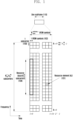
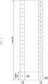
- FIG. 2 illustrates an example of a structure of a frame 200, a subframe 201, and a slot 202.
- 1 frame 200 may be defined to 10 ms.
- 1 subframe 201 may be defined to 1 ms; thus, 1 frame 200 may be composed of total 10 subframes 201.
- 1 slots 202 and 203 may be defined to 14 OFDM symbols (i.e., the number N symb slot of symbols per slot is 14).
- 1 subframe 201 may be composed of one or a plurality of slots 202 and 203, and the number of slots 202 and 203 per subframe 201 may vary according to configuration values ⁇ 204 and 205 for subcarrier spacing.
- FIG. 1 frame 200 may be defined to 10 ms.
- 1 subframe 201 may be defined to 1 ms; thus, 1 frame 200 may be composed of total 10 subframes 201.
- 1 slots 202 and 203 may be defined to 14 OFDM symbols (i.e., the number N sy
- N slot subframe , ⁇ and N slot frame , ⁇ according to each subcarrier spacing configuration ⁇ may be defined as in Table 1. [Table 1] ⁇ N symb slot N slot frame , ⁇ N slot subframe , ⁇ 0 14 10 1 1 14 20 2 2 14 40 4 3 14 80 8 4 14 160 16 5 14 320 32
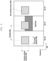
- FIG. 3 is a diagram illustrating an example of a BWP configuration in a wireless communication system according to an embodiment of the disclosure.
- FIG. 3 illustrates an example in which a UE bandwidth 300 is configured to two BWPs, that is, a BWP#1, 301 and a BWP#2, 302.
- the base station may configure one or a plurality of BWPs to the UE and configure information such as Table 2 for each BWP.
- the disclosure is not limited to the above example, and various parameters related to the BWP may be configured to the UE in addition to the configuration information.
- the information may be transmitted by the base station to the UE through higher layer signaling, for example, RRC signaling.
- RRC signaling for example, RRC signaling.
- At least one BWP among one or a plurality of configured BWPs may be activated. Whether the configured BWP is activated may be quasi-statically transmitted from the base station to the UE through RRC signaling or may be dynamically transmitted from the base station to the UE through downlink control information (DCI).
- DCI downlink control information
- the UE before RRC connection may receive a configuration of an initial BWP for initial access from the base station through a master information block (MIB). More specifically, in an initial access step, the UE may receive configuration information on a search space and a control resource set (CORESET) in which a PDCCH for receiving system information (may correspond to remaining system information (RMSI) or system information block 1 (SIB1)) necessary for initial access may be transmitted through the MIB.
- the CORESET and search space configured by the MIB may be regarded as an identity (ID) 0, respectively.
- the base station may notify the UE of configuration information such as frequency allocation information, time allocation information, and numerology for the CORESET #0 through the MIB.
- the base station may notify the UE of configuration information on a monitoring period and occasion for the CORESET #0, that is, configuration information on a search space #0 through the MIB.
- the UE may regard a frequency domain configured to the CORESET #0 acquired from the MIB as an initial BWP for initial access.
- an identity (ID) of the initial BWP may be regarded as 0.
- the configuration for the BWP supported in the 5G may be used for various purposes.
- a bandwidth supported by the UE is smaller than the system bandwidth
- this may be supported through the BWP configuration.
- the base station configures a frequency position (configuration information 2) of the BWP to the UE
- the UE may transmit and receive data at a specific frequency position within the system bandwidth.
- the base station may configure a plurality of BWPs to the UE. For example, in order to support both data transmission and reception using subcarrier spacing of 15 kHz and subcarrier spacing of 30 kHz to a certain UE, the base station may configure two BWPs to subcarrier spacings of 15 kHz and 30 kHz, respectively. Different BWPs may be frequency division multiplexed, and in the case that data is to be transmitted and received at specific subcarrier spacing, a BWP configured at corresponding subcarrier spacing may be activated.
- the base station may configure BWPs having different sizes of bandwidth to the UE. For example, in the case that the UE supports a very large bandwidth, for example, a bandwidth of 100 MHz and always transmits and receives data with the corresponding bandwidth, very large power consumption may occur. In particular, monitoring an unnecessary downlink control channel with a large bandwidth of 100 MHz in a situation in which there is no traffic may be very inefficient in terms of power consumption.
- the base station may configure a BWP of a relatively small bandwidth, for example, a BWP of 20 MHz to the UE.
- the UE may perform a monitoring operation in the BWP of 20 MHz, and in the case that data is generated, the UE may transmit and receive data with the BWP of 100 MHz according to the instruction of the base station.
- UEs before RRC connection may receive configuration information on the initial BWP through an MIB in an initial access step. More specifically, the UE may receive a configuration of a control resource set (CORESET) for a downlink control channel in which DCI scheduling the system information block (SIB) may be transmitted from the MIB of a physical broadcast channel (PBCH).
- CORESET control resource set
- PBCH physical broadcast channel
- a bandwidth of the CORESET configured by the MIB may be regarded as an initial BWP
- the UE may receive a physical downlink shared channel (PDSCH) in which the SIB is transmitted through the configured initial BWP.
- the initial BWP may be used for other system information (OSI), paging, and random access in addition to the use of receiving the SIB.
- OSI system information
- paging paging
- random access in addition to the use of receiving the SIB.
- the base station may instruct the UE to change (or switch, transition) the BWP using a BWP indicator field in the DCI.
- the base station may indicate a BWP #2, 302 by a BWP indicator in the DCI to the UE, and the UE may perform the BWP change with the BWP #2, 302 indicated by the BWP indicator in the received DCI.
- the DCI-based BWP change may be instructed by DCI scheduling the PDSCH or PUSCH
- the UE should be able to receive or transmit the PDSCH or PUSCH scheduled by the corresponding DCI in the changed BWP without difficulty.
- the standard stipulates requirements for a delay time TBWP required when changing the BWP, and may be defined as in Table 3, for example.
- [Table 3] ⁇ NR Slot length (ms) BWP switch delay T BWP (slots)
- Type 1 Note 1
- Type 2 Note 1 0 1 1 3 1 0.5 2 5 2 0.25 3 9 3 0.125 6 18
- Note 1 Depends on UE capability.
- Note 2 If the BWP switch involves changing of SCS, the BWP switch delay is determined by the larger one between the SCS before BWP switch and the SCS after BWP switch.
- the requirement for a BWP change delay time supports type 1 or type 2 according to a capability of the UE.
- the UE may report a supportable BWP delay time type to the base station.
- the UE may complete the change to a new BWP indicated by the BWP change indicator at a time point not later than a slot n+T BWP and perform transmission and reception for a data channel scheduled by the corresponding DCI in the changed new BWP.
- the base station may determine time domain resource assignment for the data channel in consideration of the BWP change delay time T BWP of the UE.
- the base station may schedule the corresponding data channel after the BWP change delay time. Accordingly, the UE may not expect that the DCI indicating the BWP change indicates a slot offset value (K0 or K2) smaller than the BWP change delay time T BWP .
- the UE may not perform any transmission or reception during a corresponding time interval from a third symbol of a slot that receives a PDCCH including the corresponding DCI to a start point of a slot indicated by a slot offset value (K0 or K2) indicated by a time domain resource assignment indicator field in the corresponding DCI.
- DCI e.g., DCI format 1_1 or 0_1
- K0 or K2 a slot offset value
- the UE may not perform any transmission or reception from a third symbol of the slot n to the previous symbol of a slot n+K (i.e., a last symbol of a slot n+K-1).
- the SS/PBCH block may mean a physical layer channel block composed of a primary SS (PSS), a secondary SS (SSS), and a PBCH. Specifically, it is as follows.
- the UE may detect the PSS and SSS in an initial access step and decode the PBCH.
- the UE may acquire an MIB from the PBCH, and receive a configuration of a control resource set (CORESET) #0 (which may correspond to a CORESET having a CORESET index of 0) therefrom.
- the UE may assume that the selected SS/PBCH block and demodulation reference signal (DMRS) transmitted in the CORESET #0 are quasi co-located (QCL) and perform monitoring for the CORESET #0.
- DMRS demodulation reference signal
- the UE may receive system information with downlink control information transmitted in the CORESET #0.
- the UE may acquire random access channel (RACH) related configuration information required for initial access from the received system information.
- RACH random access channel
- the UE may transmit a physical RACH (PRACH) to the base station in consideration of the selected SS/PBCH index, and the base station that has received the PRACH may acquire information on the SS/PBCH block index selected by the UE.
- the base station may know that the UE has selected a certain block among SS/PBCH blocks and monitors the CORESET #0 related thereto.
- the DCI may be transmitted through a physical downlink control channel (PDCCH) via channel coding and modulation processes.
- a cyclic redundancy check (CRC) is attached to a DCI message payload, and the CRC may be scrambled with a radio network temporary identifier (RNTI) corresponding to the identity of the UE.
- RNTI radio network temporary identifier
- Different RNTIs may be used according to the purpose of the DCI message, for example, UE-specific data transmission, power control command, or random access response. That is, the RNTI is not explicitly transmitted but is included in a CRC calculation process and transmitted.
- the UE may identify the CRC using the allocated RNTI, and when the CRC identification result is correct, the UE may know that the corresponding message has been transmitted to the UE.
- a DCI format 0_0 may be used as fallback DCI scheduling a PUSCH, and in this case, a CRC may be scrambled with a C-RNTI.
- the DCI format 0_0 in which a CRC is scrambled with a C-RNTI may include, for example, information of Table 4. [Table 4] - Identifier for DCI formats - [1] bit - Frequency domain resource assignment- log 2 N RB UL , BWP N RB UL , BWP + 1 / 2 bits - Time domain resource assignment - X bits - Frequency hopping flag - 1 bit.
- a DCI format 0_1 may be used as non-fallback DCI scheduling a PUSCH, and in this case, a CRC may be scrambled with a C-RNTI.
- the DCI format 0_1 in which a CRC is scrambled with a C-RNTI may include, for example, information of Table 5.
- - Modulation and coding scheme - 5 bits - New data indicator - 1 bit - Redundancy version - 2 bits - HARQ process number - 4 bits - 1st downlink assignment index- 1 or 2 bits • 1 bit for semi-static HARQ-ACK codebook; • 2 bits for dynamic HARQ-ACK codebook with single HARQ-ACK codebook.
- a DCI format 1_0 may be used as fallback DCI scheduling a PDSCH, and in this case, a CRC may be scrambled with a C-RNTI.
- the DCI format 1_0 in which a CRC is scrambled with a C-RNTI may include, for example, information of Table 6. [Table 6] - Identifier for DCI formats - [1] bit - Frequency domain resource assignment - log 2 N RB DL , BWP N RB DL , BWP + 1 / 2 bits - Time domain resource assignment - X bits - VRB-to-PRB mapping - 1 bit.
- a DCI format 1_1 may be used as non-fallback DCI scheduling a PDSCH, and in this case, a CRC may be scrambled with a C-RNTI.
- the DCI format 1_1 in which a CRC is scrambled with a C-RNTI may include, for example, information of Table 7.
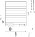
- FIG. 4 is a diagram illustrating an example of a control resource set (CORESET) in which a downlink control channel is transmitted in a 5G wireless communication system.
- CORESET control resource set
- FIG. 4 illustrates an example in which a UE BWP 410 is configured on the frequency axis and in which two CORESETs (CORESET # 1, 401 and CORESET # 2, 402) are configured within 1 slot 420 on the time axis.
- the CORESETs 401 and 402 may be configured to a specific frequency resource 403 within the entire UE BWP 410 on the frequency axis.
- One or a plurality of OFDM symbols may be configured to the time axis, and this may be defined to a control resource set duration 404.
- the CORESET #1, 401 is configured to a control resource set duration of 2 symbols
- the CORESET #2, 402 is configured to a control resource set duration of 1 symbol.
- the CORESET in 5G described above may be configured by the base station to the UE through higher layer signaling (e.g., system information, master information block (MIB), radio resource control (RRC) signaling).
- Configuring the CORESET to the UE means providing information such as a CORESET identity, a frequency location of the CORESET, and a symbol length of the CORESET. For example, it may include information of Table 8.
- 1 CCE 504 may be composed of a plurality of REGs 503.
- the REG 503 illustrated in FIG. 5 is described as an example, the REG 503 may be composed of 12 REs, and when 1 CCE 504 is composed of 6 REGs 503, 1 CCE 504 may be composed of 72 REs.
- the corresponding CORESET may be composed of a plurality of CCEs 504, and a specific downlink control channel may be mapped and transmitted to one or a plurality of CCEs 504 according to an aggregation level (AL) in the CORESET.
- the CCEs 504 in the CORESET are identified by numbers, and in this case, the numbers of the CCEs 504 may be assigned according to a logical mapping method.
- the basic unit of the downlink control channel illustrated in FIG. 5 may include both REs to which DCI is mapped and an area to which a DMRS 505, which is a reference signal for decoding them, is mapped. As illustrated in FIG. 5 , three DMRSs 505 may be transmitted within one REG 503.
- the specified RNTIs may follow the following definitions and uses.
- a search space of an aggregation level L in a CORESET p and a search space set s may be expressed as in Equation 1.
- the Y p , n s , f ⁇ value may correspond to 0 in the case of a common search space.
- the Y p , n s , f ⁇ value may correspond to a value that changes according to an identity of the UE (C-RNTI or an ID configured to the UE by the base station) and a time index.
- a set of search space sets monitored by the UE at each time point may be changed. For example, in the case that a search space set #1 is configured to an X-slot period and that a search space set #2 is configured to a Y-slot period and that X and Y are different, the UE may monitor both the search space set #1 and the search space set #2 in a specific slot and monitor one of the search space set #1 and the search space set #2 in a specific slot.
- FIG. 7 is a diagram illustrating three frequency axis resource assignment methods of type-0 (7-00), type-1 (7-05), and dynamic switch (7-10) that may be configured through an upper layer in an NR wireless communication system.
- some downlink control information (DCI) that allocates a PDSCH/PUSCH to the UE includes a bitmap composed of the NRBG number of bits.
- NRBG means the number of a resource block group (RBG) determined as illustrated in [Table 11] according to a BWP size allocated by a BWP indicator and an upper layer parameter rbg-Size, and data is transmitted to the RBG indicated as 1 by the bitmap.
- RBG resource block group
- FDRA frequency domain resource assignment
- the remaining RBGs include P number of RBs.
- P is the number of nominal RBGs determined according to Table 11.
- DCI that allocates a PDSCH/PUSCH to the UE include frequency domain resource assignment (FDRA) information composed of the log 2 N RB DL , BWP N RB DL , BWP + 1 / 2 number of bits.
- N RB BWP is the number of RBs included in the BWP.
- the base station may configure a starting VRB 7-20 and a length 7-25 of frequency axis resources continuously allocated therefrom.
- some DCI that allocates a PDSCH/PUSCH to the UE include frequency axis resource assignment information composed of bits of a payload 7-15 for configuring type-0 resource allocation and a larger value 7-25 of payloads 7-20 and 7-25 for configuring type-1 resource allocation. Conditions for this will be described later.
- one bit may be added to a most significant bit (MSB) of frequency axis resource assignment information in the DCI, and in the case that the bit has a value of '0', it may be indicated that type-0 resource allocation is used, and in the case that the bit has a value of '1', it may be indicated that type-1 resource allocation is used.
- MSB most significant bit
- the base station may notify the UE of one of entries in a table on the above-described time domain resource assignment information through L1 signaling (e.g., DCI) (e.g., may be indicated by a 'time domain resource assignment' field in the DCI).
- L1 signaling e.g., DCI
- the UE may acquire time domain resource assignment information on a PDSCH or PUSCH based on the DCI received from the base station.
- FIG. 8 is a diagram illustrating an example of time axis resource assignment of a PDSCH in a wireless communication system according to an embodiment of the disclosure.
- the base station may instruct a time axis location of a PDSCH resource according to subcarrier spacing (SCS) ⁇ PDSCH and ⁇ PDCCH and scheduling offset K0 value of a data channel and control channel configured using an upper layer, and an OFDM symbol start location 8-00 and length 8-05 within one slot dynamically indicated through DCI.
- SCS subcarrier spacing
- FIG. 9 is a diagram illustrating an example of time axis resource assignment according to subcarrier spacing of a data channel and a control channel in a wireless communication system according to an embodiment of the disclosure.
- PUSCH transmission may be dynamically scheduled by a UL grant in DCI or may operate by a configured grant Type 1 or Type 2.
- Dynamic scheduling indication for PUSCH transmission is available in a DCI format 0_0 or 0_1.
- Configured grant Type 1 PUSCH transmission may be quasi-statically configured through reception of configuredGrantConfig including rrc-ConfiguredUplinkGrant of [Table 14] through higher signaling without reception of the UL grant in DCI.
- Configured grant type 2 PUSCH transmission may be scheduled semi-persistently by the UL grant in DCI after receiving configuredGrantConfig not including rrc-ConfiguredUplinkGrant of [Table 14] through higher signaling.
- parameters applied to PUSCH transmission are applied through configuredGrantConfig, which is higher signaling of [Table 14] except for dataScramblingIdentityPUSCH, txConfig, codebookSubset, maxRank, and scaling of UCI-OnPUSCH provided to a push-Config of [Table 15], which is higher signaling.
- configuredGrantConfig which is higher signaling of [Table 14] except for dataScramblingIdentityPUSCH, txConfig, codebookSubset, maxRank, and scaling of UCI-OnPUSCH provided to a push-Config of [Table 15], which is higher signaling.
- a DMRS antenna port for PUSCH transmission is the same as an antenna port for SRS transmission.
- PUSCH transmission may follow a codebook-based transmission method and a non-codebook-based transmission method, respectively, according to whether a value of txConfig in a push-Config of [Table 15], which is higher signaling is 'codebook' or 'nonCodebook'.
- PUSCH transmission may be dynamically scheduled through a DCI format 0_0 or 0_1, and be quasi-statically configured by the configured grant.
- the UE When the UE is instructed to schedule PUSCH transmission through a DCI format 0_0, the UE performs a beam configuration for PUSCH transmission using a pucch-spatialRelationInfoID corresponding to an UE-specific PUCCH resource corresponding to the minimum ID within the activated uplink BWP in the serving cell, and in this case, PUSCH transmission is performed based on a single antenna port.
- the UE does not expect scheduling for PUSCH transmission through a DCI format 0_0 in a BWP in which a PUCCH resource including pucch-spatialRelationInfo is not configured.
- the UE does not receive a configuration of txConfig in push-Config of [Table 15], the UE does not expect to be scheduled in a DCI format 0_1.
- Codebook-based PUSCH transmission may be dynamically scheduled through a DCI format 0_0 or 0_1, and operate quasi-statically by the configured grant.
- the UE determines a precoder for PUSCH transmission based on a SRS resource indicator (SRI), transmission precoding matrix indicator (TPMI), and transmission rank (the number of PUSCH transmission layers).
- SRI SRS resource indicator
- TPMI transmission precoding matrix indicator
- transmission rank the number of PUSCH transmission layers.
- the SRI may be given through a field SRS resource indicator in DCI or may be configured through an srs-ResourceIndicator, which is higher signaling.
- the UE may receive a configuration of at least one SRS resource, and receive a configuration of maximum two SRS resources.
- the SRS resource indicated by the corresponding SRI means an SRS resource corresponding to the SRI among SRS resources transmitted earlier than the PDCCH including the corresponding SRI.
- TPMI and transmission rank may be given through a field precoding information and number of layers in DCI or may be configured through precodingAndNumberOfLayers, which is higher signaling.
- the UE transmits one or a plurality of SRS resources included in an SRS resource set in which a value of usage is configured to 'codebook' to the base station according to higher signaling, and the base station selects one of SRS resources transmitted by the UE to instruct the UE to perform PUSCH transmission using transmission beam information of the SRS resource.
- the SRI is used as information for selecting an index of one SRS resource and is included in DCI.
- the base station includes information indicating the TPMI and rank to be used by the UE for PUSCH transmission in the DCI. The UE applies a rank indicated based on a transmission beam of the corresponding SRS resource and a precoder indicated by the TPMI to perform PUSCH transmission using the SRS resource indicated by the SRI.
- Non-codebook based PUSCH transmission may be dynamically scheduled through a DCI format 0_0 or 0_1, and operate quasi-statically by the configured grant.
- the UE may receive scheduling of non-codebook based PUSCH transmission through a DCI format 0_1.
- the base station transmits one NZP-CSI-RS connected to the SRS resource set to the UE, and the UE calculates a precoder to use when transmitting one or a plurality of SRS resources in the corresponding SRS resource set based on the measurement result upon receiving the corresponding NZP-CSI-RS.
- the UE applies the calculated precoder when transmitting one or a plurality of SRS resources in the SRS resource set in which the usage is configured to 'nonCodebook' to the base station, and the base station selects one or a plurality of SRS resources among one or a plurality of received SRS resources.
- determining a priority between A and B may be variously referred to as selecting one having a higher priority according to a predetermined priority rule and performing a corresponding operation or omitting or dropping an operation for one having a lower priority.
- determining a priority between A and B may be variously referred to as selecting one having a higher priority according to a predetermined priority rule and performing a corresponding operation or omitting or dropping an operation for one having a lower priority.
- a subband non-overlapping full duplex (SBFD) is being discussed with a new duplex method based on NR.
- the SBFD is technology that receives uplink transmission from the UE as much as increased uplink resources to expand uplink coverage of the UE by utilizing a part of downlink resources as uplink resources in a TDD spectrum of frequencies of 6 GHz or less or 6 GHz or more and that receives feedback on downlink transmission from the UE in the expanded uplink resources, thereby reducing a feedback delay.
- a UE that may receive information on whether to support an SBFD from the base station and that may perform uplink transmission in a part of downlink resources may be referred to as an SBFD UE (SBFD-capable UE) for convenience.
- the following methods may be considered to define the SBFD method in the standard and in order for the SBFD UE to determine that the SBFD is supported at a specific cell (or frequency, frequency band).
- frame structure type 2 may be introduced to define the above SBFD.
- the above frame structure type 2 may be defined as being supported at the specific frequency or frequency band, or the base station may instruct to the UE whether to support an SBFD through system information.
- the SBFD UE may receive system information including whether to support an SBFD and determine whether to support an SBFD in the specific cell (or frequency, frequency band).
- Second method It may be indicated whether to additionally support the SBFD at a specific frequency or frequency band of the existing unpaired spectrum (or TDD) without defining a new frame structure type.
- the SBFD UE may receive system information including whether to support an SBFD to determine whether to support an SBFD in the specific cell (or frequency, frequency band).
- Information on whether to support an SBFD in the first and second methods may be information indicating whether to indirectly support an SBFD (e.g., SBFD resource constitution information in FIG. 11 to be described later) by additionally configuring a part of the downlink resource as an uplink resource in addition to a configuration on TDD UL (uplink)-DL (downlink) resource constitution information indicating TDD downlink slot (or symbol) resources and uplink slot (or symbol) resources or may be information indicating whether to directly support an SBFD.
- SBFD resource constitution information in FIG. 11 to be described later by additionally configuring a part of the downlink resource as an uplink resource in addition to a configuration on TDD UL (uplink)-DL (downlink) resource constitution information indicating TDD downlink slot (or symbol) resources and uplink slot (or symbol) resources or may be information indicating whether to directly support an SBFD.
- the SBFD UE may receive a synchronization signal block at initial cell access for accessing a cell (or the base station) to acquire cell synchronization.
- a process of acquiring cell synchronization may be the same in the SBFD UE and the existing TDD UE. Thereafter, the SBFD UE may determine whether the cell supports an SBFD through MIB acquisition, SIB acquisition, or a random access process.
- System information for transmitting information on whether to support the SBFD may be system information to be transmitted separately from system information for a UE (e.g., existing TDD UE) supporting another version of standard within a cell, and the SBFD UE may acquire all or part of system information to be transmitted separately from system information for the existing TDD UE to determine whether to support the SBFD.
- the SBFD UE acquires only system information for the existing TDD UE or acquires system information on non-support of an SBFD
- the SBFD UE may determine that the cell (or the base station) supports only a TDD.
- the information on whether to support the SBFD may be inserted at the very end so as to have no effect on acquisition of system information of the existing TDD UE.
- the SBFD UE fails to acquire last inserted information on whether to support the SBFD or acquires information that the SBFD is not supported, the SBFD UE may determine that the cell (or the base station) supports only a TDD.
- the information on whether to support the SBFD may be transmitted to a separate PDSCH so as to have no effect on acquisition of system information of the existing TDD UE. That is, a UE that does not support an SBFD may receive a first SIB (or SIB1) including existing TDD related system information from a first PDSCH. A UE supporting an SBFD may receive a first SIB (or SIB) including existing TDD related system information from a first PDSCH, and receive a second SIB including SBFD related system information from a second PDSCH.
- the first PDSCH and the second PDSCH may be scheduled by a first PDCCH and a second PDCCH, and a cyclic redundancy code (CRC) of the first PDCCH and the second PDCCH may be scrambled with the same RNTI (e.g., SI-RNTI).
- a search space for monitoring the second PDCCH may be acquired from system information of the first PDSCH, and if a search space for monitoring the second PDCCH is not acquired (i.e., if system information of the first PDSCH does not include information on a search space), the second PDCCH may be received in the same search space as that of the first PDCCH.
- the SBFD UE may perform random access procedures and data/control signal transmission and reception in the same way as that of an existing TDD UE.
- the base station may constitute a separate random access resource for each of the existing TDD UEs or SBFD UEs (e.g., an SBFD UE supporting duplex communication and an SBFD UE supporting half-duplex communication), and transmit constitution information (control information or constitution information indicating time-frequency resources that may be used for a PRACH) for the random access resource to the SBFD UE through system information.
- System information for transmitting information on the random access resource may be separately transmitted system information different from system information for a UE (e.g., existing TDD UE) supporting another version of standard within a cell.
- the base station may configure separate random access resources to the SBFD UE and the TDD UE supporting another version of standard to distinguish whether the TDD UE supporting the another version of standard performs random access or the SBFD UE performs random access.
- a separate random access resource configured to the SBFD UE may be a resource in which the existing TDD UE determines as a downlink time resource, and the SBFD UE may perform random access through an uplink resource (or a separate random access resource) configured to some frequencies of the downlink time resource; thus, the base station may determine that a UE that has attempted random access in the uplink resource is an SBFD UE.
- the base station may configure a common random access resource to all UEs in the cell without configuring a separate random access resource for the SBFD UE.
- constitution information on the random access resource may be transmitted to all UEs in the cell through system information, and the SBFD UE that has received the system information may perform random access to the random access resource.
- the SBFD UE may complete a random access process and proceed in an RRC connection mode for transmitting and receiving data to and from the cell.
- the SBFD UE may receive, from the base station, an upper or physical signal that may determine that some frequency resources of the downlink time resource are configured as uplink resources and perform an SBFD operation (for example, transmit an uplink signal in the uplink resource).
- the SBFD UE may transmit capability information including at least one of information on whether the UE supports an SBFD, information on whether the UE supports full-duplex communication or half-duplex communication, or the number of transmission or reception antennas in which the UE has (or supports) to the base station, thereby notifying the base station that the UE attempting to access is an SBFD UE.
- capability information including at least one of information on whether the UE supports an SBFD, information on whether the UE supports full-duplex communication or half-duplex communication, or the number of transmission or reception antennas in which the UE has (or supports) to the base station, thereby notifying the base station that the UE attempting to access is an SBFD UE.
- whether the half-duplex communication is supported may be omitted from capability information.
- Reporting of the SBFD UE on the capability information may be performed to the base station through a random access process, be performed to the base station after completing the random access process, or be performed to the base station after proceeding in an RRC connection mode for transmitting and receiving data to and from cells.
- the SBFD UE may support half-duplex communication that performs only uplink transmission or downlink reception at a single moment, as in an existing TDD UE, or the SBFD UE may support full-duplex communication that performs both uplink transmission and downlink reception at a single moment. Therefore, the SBFD UE may report information on whether the SBFD UE supports half-duplex communication or full-duplex communication to the base station through capability reporting, and after the reporting, the base station may configure to the SBFD UE whether the SBFD UE will transmit and receive using half-duplex communication or full-duplex communication. In the case that the SBFD UE reports the capability for half-duplex communication to the base station, a duplexer does not generally exist; thus, a switching gap for changing an RF may be required between transmission and reception in the case of operating in FDD or TDD.
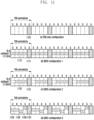
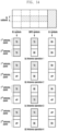
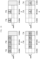
- FIG. 11 is a diagram illustrating an example of operating an SBFD in a TDD band of a wireless communication system to which the disclosure is applied.
- FIG. 11A illustrates the case that a TDD is operated in a specific frequency band.
- the base station may transmit and receive signals including data/control information in a downlink slot (or symbol), an uplink slot (or symbol) 1101, and a flexible slot (or symbol) to and from the existing TDD UE or SBFD UE based on a configuration on TDD UL-DL resource constitution information indicating TDD downlink slot (or symbol) resources and uplink slot (or symbol) resources.
- a DDDSU slot format is configured according to TDD UL-DL resource constitution information.
- 'D' is a slot composed of all downlink symbols
- 'U' is a slot composed of all uplink symbols
- 'S' is a slot other than 'D' or 'U', that is, a slot including both a downlink symbol and an uplink symbol or including a flexible symbol.
- S is composed of 12 downlink symbols and 2 flexible symbols.
- the DDDSU slot format may be repeated according to TDD UL-DL resource constitution information. That is, a repetition period of a TDD configuration may be 5 slots (5ms in the case of 15kHz SCS, 2.5ms in the case of 30kHz SCS, and the like).
Landscapes
- Engineering & Computer Science (AREA)
- Signal Processing (AREA)
- Computer Networks & Wireless Communication (AREA)
- Mobile Radio Communication Systems (AREA)
Applications Claiming Priority (2)
| Application Number | Priority Date | Filing Date | Title |
|---|---|---|---|
| KR1020220124609A KR20240044966A (ko) | 2022-09-29 | 2022-09-29 | 무선 통신 시스템에서 전이중 통신을 위한 안테나 모드 선택 방법 및 장치 |
| PCT/KR2023/015098 WO2024072138A1 (ko) | 2022-09-29 | 2023-09-27 | 무선 통신 시스템에서 전이중 통신을 위한 안테나 모드 선택 방법 및 장치 |
Publications (2)
| Publication Number | Publication Date |
|---|---|
| EP4580081A1 true EP4580081A1 (de) | 2025-07-02 |
| EP4580081A4 EP4580081A4 (de) | 2025-11-05 |
Family
ID=90478748
Family Applications (1)
| Application Number | Title | Priority Date | Filing Date |
|---|---|---|---|
| EP23873246.5A Pending EP4580081A4 (de) | 2022-09-29 | 2023-09-27 | Verfahren und vorrichtung zur auswahl eines antennenmodus für vollduplexkommunikation in einem drahtloskommunikationssystem |
Country Status (4)
| Country | Link |
|---|---|
| EP (1) | EP4580081A4 (de) |
| KR (1) | KR20240044966A (de) |
| CN (1) | CN119968790A (de) |
| WO (1) | WO2024072138A1 (de) |
Cited By (1)
| Publication number | Priority date | Publication date | Assignee | Title |
|---|---|---|---|---|
| US20250158791A1 (en) * | 2023-11-10 | 2025-05-15 | Qualcomm Incorporated | Variable subband locations for subband full duplex configurations |
Families Citing this family (2)
| Publication number | Priority date | Publication date | Assignee | Title |
|---|---|---|---|---|
| US20240334178A1 (en) * | 2023-03-31 | 2024-10-03 | Qualcomm Incorporated | User equipment sub-band full duplex |
| WO2025021892A1 (en) * | 2023-07-27 | 2025-01-30 | Sony Group Corporation | Methods, communications devices and infrastructure equipment |
Family Cites Families (7)
| Publication number | Priority date | Publication date | Assignee | Title |
|---|---|---|---|---|
| KR101896001B1 (ko) * | 2011-07-12 | 2018-09-06 | 한국전자통신연구원 | 이종 네트워크 환경에서 단말의 이동성 관리 방법 |
| US11424799B2 (en) * | 2018-06-12 | 2022-08-23 | Google Llc | Beamforming-based grant-free non-orthogonal multiple access transmission |
| US11228353B2 (en) * | 2018-08-09 | 2022-01-18 | Qualcomm Incorporated | Beamforming in non-reciprocal uplink and downlink channels |
| US11509383B2 (en) * | 2019-12-23 | 2022-11-22 | Qualcomm Incorporated | Default physical downlink shared channel downlink beam determination with self-interference |
| CN115226117B (zh) * | 2020-02-07 | 2024-07-02 | 维沃移动通信有限公司 | 波束指示方法、装置、设备及介质 |
| US12095609B2 (en) * | 2020-05-01 | 2024-09-17 | Samsung Electronics Co., Ltd. | Method and apparatus for beam-specific downlink/uplink operation |
| US11425721B2 (en) * | 2020-12-04 | 2022-08-23 | Qualcomm Incorporated | Methods and apparatus to facilitate duplex mode per uplink control channel resource |
-
2022
- 2022-09-29 KR KR1020220124609A patent/KR20240044966A/ko active Pending
-
2023
- 2023-09-27 WO PCT/KR2023/015098 patent/WO2024072138A1/ko not_active Ceased
- 2023-09-27 CN CN202380069664.0A patent/CN119968790A/zh active Pending
- 2023-09-27 EP EP23873246.5A patent/EP4580081A4/de active Pending
Cited By (1)
| Publication number | Priority date | Publication date | Assignee | Title |
|---|---|---|---|---|
| US20250158791A1 (en) * | 2023-11-10 | 2025-05-15 | Qualcomm Incorporated | Variable subband locations for subband full duplex configurations |
Also Published As
| Publication number | Publication date |
|---|---|
| WO2024072138A1 (ko) | 2024-04-04 |
| KR20240044966A (ko) | 2024-04-05 |
| CN119968790A (zh) | 2025-05-09 |
| EP4580081A4 (de) | 2025-11-05 |
Similar Documents
| Publication | Publication Date | Title |
|---|---|---|
| US20250301505A1 (en) | Method and device for random access in wireless communication system | |
| US20230155747A1 (en) | Method and apparatus for multiple physical shared channel scheduling in wireless communication systems | |
| EP4175393B1 (de) | Verfahren und vorrichtung zum senden/empfangen von uplink-datenwiederholungen für kooperative netzwerkkommunikationen | |
| US20250167954A1 (en) | Method and device for uplink data channel transmission in wireless communication system | |
| US12550130B2 (en) | Method and apparatus for transmission and reception based on predicted transmission configuration information in wireless communication systems | |
| EP4580081A1 (de) | Verfahren und vorrichtung zur auswahl eines antennenmodus für vollduplexkommunikation in einem drahtloskommunikationssystem | |
| EP4568384A1 (de) | Planungsverfahren und -vorrichtung für vollduplexkommunikation in einem drahtloskommunikationssystem | |
| KR20240110247A (ko) | 무선 통신 시스템에서 sbfd 기반의 통신을 수행하기 위한 방법 및 장치 | |
| US20250039800A1 (en) | Method and device for controlling uplink power in wireless communication system | |
| EP4598219A1 (de) | Planungsverfahren und -vorrichtung für vollduplexkommunikation in einem drahtloskommunikationssystem | |
| EP4580282A1 (de) | Verfahren und vorrichtung zur konfiguration von frequenzressourcen für vollduplexkommunikation in einem drahtloskommunikationssystem | |
| US20230345484A1 (en) | Method and apparatus for multi-cell scheduling and harq-ack transmission in wireless communication system | |
| US20250266964A1 (en) | Method and device for transmitting channel state information of terminal in wireless communication system | |
| US20250142576A1 (en) | Method and apparatus for transmitting and receiving uplink control information in wireless communication systems | |
| US20250105871A1 (en) | Method and device for uplink precoding in wireless communication system | |
| EP4604436A1 (de) | Verfahren und vorrichtung für referenzsignalübertragung/-empfang und ratenanpassung für vollduplexkommunikation in einem drahtloskommunikationssystem | |
| EP4366221A1 (de) | Verfahren und vorrichtung für wiederholungsschema für downlink-datenkanal in kommunikationssystemen | |
| EP4496413A1 (de) | Verfahren und vorrichtung zur planung mehrerer gemeinsam genutzter kanäle in einem drahtloskommunikationssystem | |
| KR20250062271A (ko) | 무선 통신 시스템에서 harq-ack 코드북 생성 및 전송 방법 및 장치 | |
| KR20250056608A (ko) | 무선 통신 시스템에서 상향링크 제어 정보 전송 방법 및 장치 | |
| KR20240174621A (ko) | 무선 통신 시스템에서 전이중 통신을 위한 harq 코드북 설계 방법 및 장치 | |
| JP2025511982A (ja) | 無線通信システムにおけるダウンリンク制御情報の解釈方法及び装置 | |
| EP4668983A1 (de) | Verfahren und vorrichtung zur bestimmung einer geplanten zelle in einem kommunikationssystem | |
| EP4676152A1 (de) | Verfahren und vorrichtung zur bestimmung eines übertragungskonfigurationsindikators für mehrzellenplanung in einem drahtloskommunikationssystem | |
| US20250300797A1 (en) | Method and apparatus for transmitting uplink channel and signal in wireless communication system |
Legal Events
| Date | Code | Title | Description |
|---|---|---|---|
| STAA | Information on the status of an ep patent application or granted ep patent |
Free format text: STATUS: THE INTERNATIONAL PUBLICATION HAS BEEN MADE |
|
| PUAI | Public reference made under article 153(3) epc to a published international application that has entered the european phase |
Free format text: ORIGINAL CODE: 0009012 |
|
| STAA | Information on the status of an ep patent application or granted ep patent |
Free format text: STATUS: REQUEST FOR EXAMINATION WAS MADE |
|
| 17P | Request for examination filed |
Effective date: 20250327 |
|
| AK | Designated contracting states |
Kind code of ref document: A1 Designated state(s): AL AT BE BG CH CY CZ DE DK EE ES FI FR GB GR HR HU IE IS IT LI LT LU LV MC ME MK MT NL NO PL PT RO RS SE SI SK SM TR |
|
| A4 | Supplementary search report drawn up and despatched |
Effective date: 20251002 |
|
| RIC1 | Information provided on ipc code assigned before grant |
Ipc: H04B 7/06 20060101AFI20250926BHEP Ipc: H04B 7/08 20060101ALI20250926BHEP Ipc: H04L 5/14 20060101ALI20250926BHEP Ipc: H04W 88/08 20090101ALI20250926BHEP |
|
| DAV | Request for validation of the european patent (deleted) | ||
| DAX | Request for extension of the european patent (deleted) | ||
| STAA | Information on the status of an ep patent application or granted ep patent |
Free format text: STATUS: THE APPLICATION HAS BEEN WITHDRAWN |