EP4580103A1 - Procédé et dispositif à utiliser dans un noeud de communication sans fil - Google Patents
Procédé et dispositif à utiliser dans un noeud de communication sans fil Download PDFInfo
- Publication number
- EP4580103A1 EP4580103A1 EP23849399.3A EP23849399A EP4580103A1 EP 4580103 A1 EP4580103 A1 EP 4580103A1 EP 23849399 A EP23849399 A EP 23849399A EP 4580103 A1 EP4580103 A1 EP 4580103A1
- Authority
- EP
- European Patent Office
- Prior art keywords
- cell
- trigger state
- message
- csi
- state set
- Prior art date
- Legal status (The legal status is an assumption and is not a legal conclusion. Google has not performed a legal analysis and makes no representation as to the accuracy of the status listed.)
- Pending
Links
Images



Classifications
-
- H—ELECTRICITY
- H04—ELECTRIC COMMUNICATION TECHNIQUE
- H04L—TRANSMISSION OF DIGITAL INFORMATION, e.g. TELEGRAPHIC COMMUNICATION
- H04L5/00—Arrangements affording multiple use of the transmission path
- H04L5/0001—Arrangements for dividing the transmission path
- H04L5/0003—Two-dimensional division
- H04L5/0005—Time-frequency
- H04L5/0007—Time-frequency the frequencies being orthogonal, e.g. OFDM(A) or DMT
- H04L5/001—Time-frequency the frequencies being orthogonal, e.g. OFDM(A) or DMT the frequencies being arranged in component carriers
-
- H—ELECTRICITY
- H04—ELECTRIC COMMUNICATION TECHNIQUE
- H04B—TRANSMISSION
- H04B7/00—Radio transmission systems, i.e. using radiation field
- H04B7/02—Diversity systems; Multi-antenna system, i.e. transmission or reception using multiple antennas
- H04B7/04—Diversity systems; Multi-antenna system, i.e. transmission or reception using multiple antennas using two or more spaced independent antennas
- H04B7/06—Diversity systems; Multi-antenna system, i.e. transmission or reception using multiple antennas using two or more spaced independent antennas at the transmitting station
- H04B7/0613—Diversity systems; Multi-antenna system, i.e. transmission or reception using multiple antennas using two or more spaced independent antennas at the transmitting station using simultaneous transmission
- H04B7/0615—Diversity systems; Multi-antenna system, i.e. transmission or reception using multiple antennas using two or more spaced independent antennas at the transmitting station using simultaneous transmission of weighted versions of same signal
- H04B7/0619—Diversity systems; Multi-antenna system, i.e. transmission or reception using multiple antennas using two or more spaced independent antennas at the transmitting station using simultaneous transmission of weighted versions of same signal using feedback from receiving side
- H04B7/0621—Feedback content
- H04B7/0626—Channel coefficients, e.g. channel state information [CSI]
-
- H—ELECTRICITY
- H04—ELECTRIC COMMUNICATION TECHNIQUE
- H04L—TRANSMISSION OF DIGITAL INFORMATION, e.g. TELEGRAPHIC COMMUNICATION
- H04L1/00—Arrangements for detecting or preventing errors in the information received
- H04L1/0001—Systems modifying transmission characteristics according to link quality, e.g. power backoff
- H04L1/0023—Systems modifying transmission characteristics according to link quality, e.g. power backoff characterised by the signalling
- H04L1/0026—Transmission of channel quality indication
-
- H—ELECTRICITY
- H04—ELECTRIC COMMUNICATION TECHNIQUE
- H04L—TRANSMISSION OF DIGITAL INFORMATION, e.g. TELEGRAPHIC COMMUNICATION
- H04L1/00—Arrangements for detecting or preventing errors in the information received
- H04L1/0001—Systems modifying transmission characteristics according to link quality, e.g. power backoff
- H04L1/0023—Systems modifying transmission characteristics according to link quality, e.g. power backoff characterised by the signalling
- H04L1/0027—Scheduling of signalling, e.g. occurrence thereof
-
- H—ELECTRICITY
- H04—ELECTRIC COMMUNICATION TECHNIQUE
- H04L—TRANSMISSION OF DIGITAL INFORMATION, e.g. TELEGRAPHIC COMMUNICATION
- H04L5/00—Arrangements affording multiple use of the transmission path
- H04L5/003—Arrangements for allocating sub-channels of the transmission path
- H04L5/0053—Allocation of signalling, i.e. of overhead other than pilot signals
- H04L5/0055—Physical resource allocation for ACK/NACK
-
- H—ELECTRICITY
- H04—ELECTRIC COMMUNICATION TECHNIQUE
- H04L—TRANSMISSION OF DIGITAL INFORMATION, e.g. TELEGRAPHIC COMMUNICATION
- H04L5/00—Arrangements affording multiple use of the transmission path
- H04L5/003—Arrangements for allocating sub-channels of the transmission path
- H04L5/0053—Allocation of signalling, i.e. of overhead other than pilot signals
- H04L5/0057—Physical resource allocation for CQI
-
- H—ELECTRICITY
- H04—ELECTRIC COMMUNICATION TECHNIQUE
- H04L—TRANSMISSION OF DIGITAL INFORMATION, e.g. TELEGRAPHIC COMMUNICATION
- H04L5/00—Arrangements affording multiple use of the transmission path
- H04L5/003—Arrangements for allocating sub-channels of the transmission path
- H04L5/0044—Allocation of payload; Allocation of data channels, e.g. PDSCH or PUSCH
-
- H—ELECTRICITY
- H04—ELECTRIC COMMUNICATION TECHNIQUE
- H04W—WIRELESS COMMUNICATION NETWORKS
- H04W72/00—Local resource management
- H04W72/20—Control channels or signalling for resource management
- H04W72/21—Control channels or signalling for resource management in the uplink direction of a wireless link, i.e. towards the network
Definitions
- the present application relates to transmission methods and devices in wireless communication systems, in particular to schemes and apparatuses related to wireless communication systems and Channel Status Information (CSI).
- CSI Channel Status Information
- UE reporting may include at least one of a variety of ancillary information, such as CSI, Beam Management-related ancillary information, location-related ancillary information, and the like.
- CSI includes at least one of CSI-Reference Signal Resource Indicator (CRI), Rank Indicator (RI), Precoding Matrix Indicator (PMI), or Channel Quality Indicator (CQI).
- the network device selects the appropriate transmission parameters for UE based on the UE reporting, such as residing in the cell, Modulation and Coding Scheme (MCS), Transmitted Precoding Matrix Indicator (TPMI), Transmission Configuration Indicator (TCI), etc. Further, the UE Reporting may be used to optimize network parameters such as better cell coverage, switch base stations based on the UE location, and the like.
- MCS Modulation and Coding Scheme
- TPMI Transmitted Precoding Matrix Indicator
- TCI Transmission Configuration Indicator
- the UE Reporting may be used to optimize network parameters such as better cell coverage, switch base stations based on the UE location, and the like.
- CSI Reporting may be periodic, semi-persistent, or aperiodic.
- Semi-persistent CSI reporting needs to be activated by Downlink Control Information (DCI) or Medium Access Control Layer Control Element (MAC CE), and non-cyclical CSI reporting needs to be triggered by DCI.
- DCI Downlink Control Information
- MAC CE Medium Access Control Layer Control Element
- the Physical Uplink Shared Channel (PUSCH)/Physical Downlink Shared Channel (PDSCH) of one DCI scheduling a plurality of cells is proposed.
- the inventor has found through research that in the present application scenario, the existing CSI reporting trigger schemes may no longer be applicable.
- a method for use in a first node for wireless communication wherein it comprises:
- the above method can adjust the trigger state set dependent on the first domain based on the cells scheduled by the first DCI, thereby improving scheduling flexibility.
- the above method can adjust the trigger state set dependent on the first domain based on the cells scheduled by the first DCI, thereby reducing redundant overhead.
- the first message indicates a first CSI-AperiodicTriggerStateList
- the first trigger state set and the second trigger state set both belong to the first CSI-AperiodicTriggerStateList.
- the above method achieves load balancing and reduces CSI omission.
- the first message set comprises a second message
- the first message and the second message indicating a first CSI-AperiodicTrigerStateList and a second CSI-AperiodicTriggerStateList, respectively
- the first trigger state set and the second trigger state set belong to the first CSI-AperiodicTrigerStateList and the second CSI-AperiodicTrigerStateList , respectively.
- the above methods have better compatibility.
- the second message being configured to the second cell.
- a method for use in a second node for wireless communication wherein it comprises:
- the first message indicates a first CSI-AperiodicTriggerStateList
- the first trigger state set and the second trigger state set both belong to the first CSI-AperiodicTriggerStateList.
- the first message set comprises a second message
- the first message and the second message indicating a first CSI-AperiodicTrigerStateList and a second CSI-AperiodicTriggerStateList, respectively
- the first trigger state set and the second trigger state set belong to the first CSI-AperiodicTrigerStateList and the second CSI-AperiodicTrigerStateList , respectively.
- the second message being configured to the second cell.
- a first node for wireless communication wherein it comprises:
- a second node for wireless communication wherein it comprises:
- the present application has the following advantages over conventional schemes:
- Embodiment 1 exemplifies a flow diagram of a first message set, a first DCI and a first CSI Reporting according to one embodiment of the present application, as shown in FIG. 1 .
- each box represents a step.
- the sequence of steps in the box does not represent a specific temporal relation between steps, and the steps in box F10 are optional.
- the first node 100 receives a first message set in step 101, the first message set comprising a first message, and the first message being used to indicate a first trigger state set, the first message being configured for a first cell, and the first trigger state set comprising at least one trigger state; in step 102, a first DCI is received on the first cell, and the first DCI being used to schedule PUSCH on at least one cell; in step 103, at least a first CSI report is transmitted on the PUSCH of a second cell, and the second cell being one cell in at least one cell; in step 104, PUSCH is respectively transmitted on other cells excluding the second cell, and the other cells excluding the second cell being the other cells excluding the second cell in at least one cell.
- the first DCI comprises a first domain, and the first domain in the first DCI is used to trigger the first CSI Reporting; the first domain in the first DCI indicates a target trigger state from a dependent trigger state set, and the target trigger state is used to configure the first CSI Reporting; the dependent trigger state set is associated with at least one cell; when at least one cell includes only the second cell, the dependent trigger state set is the first trigger state set; when at least one cell includes a third cell, the dependent trigger state set is the second trigger state set.
- the DCI refers to: Downlink Control Information.
- the CSI refers to: Channel State Information.
- the PUSCH refers to: Physical Uplink Shared Channel.
- the first message set is carried by higher layer signaling.
- the first message set is carried by Radio Resource Control (RRC) signaling.
- RRC Radio Resource Control
- the first message set is carried by the RRC IE (Information Element).
- the first message set includes a RRC IE.
- the first message set includes a CSI-MeasConfig IE.
- the first message set includes information in all or part of the domain in a CSI-MeasConfig IE.
- the first message set consists of the first message.
- the first message is carried by a RRC signaling.
- the first message is carried by a RRC IE.
- the first message includes a RRC IE.
- the first message includes a CSI-MeasConfig IE.
- the first message is a CSI-MeasConfig IE.
- the first message includes information in all or part of the domain in a CSI-AperiodicTrigerStateList IE.
- the first message is a CSI-AperiodicTriggerStateList IE.
- the first cell is a serving cell of the first node 100.
- the first node 100 performs a secondary serving cell addition for the first cell.
- the first node 100 is assigned SCelllndex or ServCellIndex for the first cell.
- the first DCI is transmitted in Physical Downlink Control Channel (PDCCH) in a first cell.
- PDCCH Physical Downlink Control Channel
- the frequency domain resource occupied by the first DCI belongs to the first cell.
- PUSCH on at least one cell scheduled by the first DCI includes PUSCH on the first cell.
- PUSCH on at least one cell of the first DCI scheduling includes PUSCH on another cell in addition to the second cell.
- the SpCellConfig or SCellConfig indicated cell index of the ControlResourceSet IE of the CORESET of the first DCI is configured to be equal to the cell index of the first cell.
- the first DCI consists of a first domain.
- the first DCI includes another DCI domain in addition to the first domain.
- the first domain in the first DCI includes at least one DCI domain.
- the first domain in the first DCI comprises a plurality of DCI domains.
- the first domain in the first DCI is a DCI domain.
- the first domain in the first DCI includes a CSI request.
- the first domain in the first DCI includes all or part of the information in a CSI request.
- the first domain in the first DCI is a CSI request.
- the first domain includes up to 6 bits.
- the second cell is a serving cell of the first node 100.
- the serving cell is defined in 3GPP TS 38.331.
- the second trigger state set is carried by RRC signaling.
- the second trigger state set includes all or part of the trigger states of a CSI-AperiodicTriggerStateList.
- the first trigger state set and the second trigger state set are respectively configured.
- the first trigger state set and the second trigger state set belong to the same CSI-AperiodicTriggerStateList.
- the target trigger state is a CSI-AperiodicTriggerState.
- the first message is used to configure a CSI-ReportConfig corresponding to the first CSI.
- the first message includes a CSI-ReportConfig IE corresponding to the first CSI.
- the first message includes a CSI-MeasConfig IE belongs to a CSI-ReportConfigl corresponds to the first CSI.
- the first CSI Reporting is only transmitted on the PUSCH on the second cell.
- the first CSI Reporting is only transmitted on the second cell on a PUSCH scheduled by the first DCI.
- the first domain in the first DCI indicates a trigger state of the first CSI.
- the first domain in the first DCI indicates a trigger state of CSI-ReportConfig corresponding to the first CSI.
- the trigger state of CSI-ReportConfig corresponding to the first CSI is configured for RRC signaling.
- the trigger state of CSI-ReportConfig corresponding to the first CSI is configured by CSI-AperiodicTriggerStateList IE.
- the trigger state of the CSI-ReportConfig corresponding to the first CSI is configured in a first trigger state set.
- the trigger state of CSI-ReportConfig corresponding to the first CSI is configured with a second trigger state set.
- the first CSI includes at least one of CQI, PMI, CRI, Layer Indicator (LI), RI, SS/PBCH Block Resource Indicator (SSBRI), Layer 1 Reference Signal Received Power (L1-RSRP), Layer 1 Signal-to-Noise and Interference Ratio (L1-SINR).
- CQI CQI
- PMI CRI
- CRI Layer Indicator
- RI RI
- SSBRI Layer 1 Reference Signal Received Power
- L1-RSRP Layer 1 Reference Signal Received Power
- L1-SINR Layer 1 Signal-to-Noise and Interference Ratio
- the first node 100 first performs channel measurement for a CSI-RS resource to obtain a channel parameter matrix H r ⁇ t , wherein r and t represent the number of receive antennas and the number of antenna ports used for transmission, respectively; under the condition of using a precoding matrix W t ⁇ l , the precoded channel parameter matrix H r ⁇ t ⁇ W t ⁇ l is obtained, where l represents the rank or the number of layers; an equivalent channel capacity of H r ⁇ t ⁇ W t ⁇ l is calculated based on criteria such as SINR, Exponential Effective SINR Mapping (EESM), or Received Block mean mutual Information Ratio (RBIR), then the CQI is determined based on the equivalent channel capacity, for example, by using a lookup table.
- EESM Exponential Effective SINR Mapping
- RBIR Received Block mean mutual Information Ratio
- a calculation of generally equivalent channel capacity requires the first node estimating noise and interference.
- the mapping between the values of equivalent channel capacity to CQI depends on the performance of the receiver, or hardware-related factors such as modulation methods.
- the pre-coding matrix W t ⁇ l is typically feedback by the first node through RI or PMI.
- the L1-SINR does not carry the information of the receiver, thus omitting the calculation of equivalent channel capacity described above.
- Embodiment 2 illustrates a schematic diagram of a network architecture according to one embodiment of the present application, as shown in FIG. 2 .
- FIG. 2 illustrates a network architecture of a Long-Term Evolution (LTE), Long-Term Evolution Advanced (LTE-A) and future 5G system.
- LTE Long-Term Evolution
- LTE-A Long-Term Evolution Advanced
- EPS Evolved Packet System
- the 5G NR or LTE network architecture may be referred to as 5G System (5GS)/EPS 200 or some other suitable term.
- the 5GS/EPS 200 may include one or more User Equipment (UE) 201, one UE241 for Sidelink communication with UE201, a Next Generation Radio Access Network (NG-RAN) 202, a 5G Core Network (5G-CN)/Evolved Packet Core (EPC) 210, a Home Subscriber Server (HSS)/Unified Data Management (UDM) 220, and an Internet service 230.
- UE User Equipment
- NG-RAN Next Generation Radio Access Network
- 5G-CN 5G Core Network
- EPC Evolved Packet Core
- HSS Home Subscriber Server
- UDM Unified Data Management
- the 5GS/EPS 200 may be interconnected with other access networks, but these entities/interfaces are not shown for simplicity.
- the 5GS/EPS 200 provides packet exchange services, however it will be readily understood by those skilled in the art that various concepts presented throughout the present application can be extended to a network providing circuit exchange services.
- the NG-RAN 202 includes NR node B(gNB) 203 and other gNB 204.
- the gNB 203 provides user and control plane protocol termination towards the UE 201.
- the gNB 203 may be connected to the other gNB 204 via an Xn interface (e.g., backhaul).
- the gNB 203 may also be referred to as a base station, a base transceiver station, a radio base station, a radio transceiver, a transceiver function, a Base Service Set (BSS), an Extension Service Set (ESS), a Transmitter Receiver Point (TRP), or some other suitable term.
- gNB 203 provides access points to 5G-CN/EPC 210 for UE 201.
- Examples of the UE 201 include cellular phones, smart phones, Session Initiation Protocol (SIP) phones, laptop computers, Personal Digital Assistant (PDA), satellite radios, global positioning systems, multimedia devices, video devices, digital audio players (e.g., MP3 players), cameras, game consoles, drones, aircraft, narrow band physical network devices, machine type communications devices, land vehicles, automobiles, wearable devices, or any other similar functional apparatuses.
- SIP Session Initiation Protocol
- PDA Personal Digital Assistant
- satellite radios global positioning systems
- multimedia devices video devices
- digital audio players e.g., MP3 players
- cameras e.g., digital audio players (e.g., MP3 players)
- game consoles e.g., drones, aircraft, narrow band physical network devices, machine type communications devices, land vehicles, automobiles, wearable devices, or any other similar functional apparatuses.
- UE 201 may also refer to the UE 201 as a mobile station, a subscriber station, a mobile unit, a subscriber unit, a wireless unit, a remote unit, a mobile device, a wireless device, a wireless communication device, a remote device, a mobile subscriber station, an access terminal, a mobile terminal, a wireless terminal, a remote terminal, a handheld, an user agent, a mobile client, a client, or some other suitable term.
- the gNB 203 is connected to the 5G-CN/EPC 210 via an S1/NG interface.
- the 5G-CN/EPC 210 includes Mobility Management Entity (MME)/Authentication Management Field (AMF)/Session Management Function (SMF) 211, other MME/AMF/SMF 214, Service Gateway (S-GW)/User Plane Function (UPF) 212 and Packet Date Network Gateway (P-GW)/UPF 213.
- MME Mobility Management Entity
- AMF Access Management Field
- S-GW Service Gateway
- P-GW Packet Date Network Gateway
- the MME/AMF/SMF 211 is a control node that processes signaling between the UE 201 and the 5G-CN/EPC 210.
- the MME/AMF/SMF 211 provides carrier and connection management. All user Internet Protocol (IP) packets are transmitted via the S-GW/UPF 212, which is itself connected to the P-GW/UPF 213.
- IP Internet Protocol
- the P-GW provides UE IP address assignment along with other functions.
- the P-GW/UPF 213 is connected to the Internet service 230.
- the Internet service 230 includes an operator's corresponding Internet protocol service, which may specifically include the Internet, an intranet, an IP Multimedia Subsystem (IMS) and a Packet switching service.
- IMS IP Multimedia Subsystem
- the first node in the present application includes the UE 201.
- the second node in the present application includes the gNB 203.
- the wireless link between the UE 201 and the gNB 203 includes a cellular network link.
- the receiver of the first DCI includes the UE 201.
- the RLC sublayer 303 provides segmentation and reassembly of the upper layer data packet, retransmission of the missing data packet, and reordering of the data packet to compensate for out-of-order reception due to HARQ.
- the MAC sublayer 302 provides multiplexes between logical and transmission channels.
- the MAC sublayer 302 is also responsible for distributing various radio resources (e.g., resource blocks) in one cell between the first communication node devices.
- the MAC sublayer 302 is also responsible for HARQ operations.
- the RRC sublayer 306 in the L3 in the control plane 300 is responsible for obtaining the radio resources (i.e., the radio carrier) and configuring the lower layer using RRC signaling between the second communication node device and the first communication node device.
- the wireless protocol architecture in FIG. 3 applies to the first node in the present application.
- the wireless protocol architecture in FIG. 3 applies to the second node in the present application.
- the first message set is generated at the RRC sublayer 306.
- the first DCI is generated at the PHY 301, or the PHY 351.
- the higher layer in the present application refers to a layer above the physical layer.
- Embodiment 4 exemplifies a schematic diagram of a first communications device and a second communications device according to one embodiment of the present application, as shown in FIG. 4.
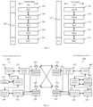
- FIG. 4 is a block diagram of a first communications device 410 and a second communications device 450 in communication with one another over an access network.
- the first communications device 410 includes a controller/processor 475, a memory 476, a receiving processor 470, a transmitting processor 416, a multi-antenna receiving processor 472, a multi-antenna transmitting processor 471, a transmitter/receiver 418, and an antenna 420.
- the second communications device 450 includes a controller/processor 459, a memory 460, a data source 467, a transmitting processor 468, a receiving processor 456, a multi-antenna transmitting processor 457, a multi-antenna receiving processor 458, a transmitter/receiver 454, and an antenna 452.
- each message in the first message set is transmitted in PDSCH.
- the first DCI is transmitted in PDCCH.
- the first RS resource group includes only one RS resource.
- the first RS resource group includes a plurality of RS resources.
- the first RS resource group is identified by an NZP-CSI-RS-ResourceSetId.
- the first RS resource group is identified by a CSI-SSB-ResourceSetId.
- the first RS resource group is a CSI-IM resource set.
- the first RS resource group includes at least one CSI-RS resource set and at least one CSI-IM resource set.
- an RS resource in the first RS resource group that is a Synchronization Signal (SS)/Physical Broadcast Channel (PBCH) block resource.
- SS Synchronization Signal
- PBCH Physical Broadcast Channel
- any of the RS resources in the first RS resource group is a CSI-RS resource, an SS/PBCH Block resource, or a CSI-IM resource.
- any of the RS resources in the first RS resource group is a downlink RS resource.
- any of the RS resources in the first RS resource group includes at least one RS port.
- the RS port includes a CSI-RS port.
- the first RS resource group is a CSI-RS resource set
- the CSI-RS resource set is identified by an NZP-CSI-RS-ResourceSetId.
- the first RS resource group is a CSI-RS resource set
- the CSI-RS resource set is configured by an NZP-CSI-RS-ResourceSet IE.
- the first RS resource group is a CSI-RS resource set
- the CSI-RS resource set comprises at least one CSI-RS resource
- the first RS resource group is a CSI-RS resource set
- the CSI-RS resource set comprises at least CSI-RS resource
- the CSI-RS resource is identified by one NZP-CSI-RS-ResourceId
- the first RS resource group is a CSI-RS resource set
- the CSI-RS resource set comprises at least one CSI-RS resource
- the CSI-RS resource is configured by an NZP-CSI-RS-Resource IE.
- the first RS resource group is a CSI-IM resource set
- the CSI-IM resource set is configured by a CSI-IM-ResourceSet IE.
- the first RS resource group is a CSI-IM resource set that includes at least one CSI-IM resource.
- the first RS resource group is a CSI-IM resource set comprising at least one CSI-IM resource identified by a CSI-IM-ResourceId.
- the first RS resource group is a CSI-IM resource set
- the one CSI-IM resource set comprises at least one CSI-IM resource
- the one CSI-IM resource is configured by a CSI-IM-Resource IE.
- the SS/PBCH Block resource is identified by an SSB-Index.
- the measurement performed on the first RS resource group comprises: a measurement performed on each of the RS resources in the first RS resource group.
- the measurement is performed on at least one RS resource in the first RS resource group.
- the measurement of the RS signal transmitted in each of the RS resources of the first RS resource group is a sub-embodiment of the above embodiment.
- the measurement of the RS signal transmitted in at least one RS resource of the first RS resource group is performed.
- the measurement performed on the first RS resource group includes channel measurement.
- the measurement performed on the first RS resource group is a channel measurement.
- the measurement performed on the first RS resource group comprises an interference measurement.
- the first node 100 obtains a channel measurement for calculating the first CSI Reporting based on the measurement performed on the first RS resource group.
- the first node 100 obtains an interference measurement for calculating the first CSI Reporting based on the measurement performed on the first RS resource group.
- the step in box F51 in FIG. 5 is present and the method used in the second node for wireless communication comprises: sending PUSCH on other cell except the second cell.
- other cells other than the second cell is a cell other than the second cell in at least one cell scheduled by the first DCI.
- the PUSCH being sent on other cells except the second cell comprises a CSI Reporting.
- the PUSCH being sent on other cells except the second cell comprises a plurality of CSI Reporting.
- the PUSCH being respectively sent on other cell except the second cell are each a CSI Reporting.
- the PUSCH being respectively sent on other cell except the second cell comprises one UL-SCH.
- the PUSCH being respectively sent on other cell except the second cell comprises a plurality of UL-SCH.
- the PUSCH being respectively sent on other cell except the second cell is an UL-SCH.
- the step in boxes F51 in FIG. 5 is present and the method used in the second node for wireless communication comprises: receiving PUSCH on other cell except the second cell.
- other cells other than the second cell is a cell other than the second cell in at least one cell scheduled by the first DCI.
- the PUSCH being respectively received on other cell except the second cell comprises a CSI Reporting.
- the PUSCH being respectively received on other cell except the second cell comprises a plurality of UL-SCH.
- Embodiment 6 exemplifies a schematic diagram of a first DCI structure according to one embodiment of the present application, as shown in FIG. 6 .
- the M domain subsets include respectively M different DCI domains.
- any two sub-domains in the M domain subsets include different bits in a given DCI domain in the first DCI.
- the first domain in the first DCI is a subdomain in the domain subset of the M domain subsets.
- the first domain in the first DCI is a domain subset in the M domain subsets, and the domain subset comprising part or all of the bits of a CSI request.
- the first domain in the first DCI is a domain subset in the M domain subsets, and the domain subset is a CSI request.
- two domain subsets in the M domain subsets includes a CSI request, respectively.
- two domain subsets of domains in the M domain subsets comprising part or all of the bits of a CSI request, respectively.
- the two domain subsets are used to trigger CSI Reporting on two cells, respectively, and the two cells are two cells in the M cells.
- At least two domain subsets depends on two trigger state sets, and the two trigger state sets belonging to the same CSI-AperiodicTriggerList.
- the two domain subsets depends on two trigger state sets respectively, and the two trigger state sets belong to the same CSI-AperiodicTriggerList , and one of the same CSI-AperiodicTriggerList belongs to the two trigger state sets simultaneously.
- the two domain subsets depends on two trigger state sets respectively, and the two trigger state sets belong to the same CSI-AperiodicTriggerList , and one trigger state in the same CSI-AperiodicTriggerList belongs to one trigger state set in addition to the two trigger state sets.
- any of the M domain subsets includes a CSI request.
- any of the M domain subsets is a CSI request.
- any of the M domain subsets includes all or part of the bits of a CSI request.
- the M domain subsets are used to trigger CSI reporting on the M cells, respectively, and the M cells are M cells scheduled by the M domain subsets of the first DCI.
- the M domain subsets depends on M trigger state sets, and the M trigger state sets belong to the same CSI-AperiodicTriggerList , and the M trigger state sets correspond to the M cells one by one, which the corresponding relationship may be implicit or explicit.
- the M domain subsets depends on M trigger state sets, and the M trigger state sets belong to the same CSI-AperiodicTriggerList , and the M trigger state sets include the same number of trigger states, respectively.
- the M domain subsets depends on M trigger state sets, and the M trigger state sets belong to the same CSI-AperiodicTriggerList , and there are at least two trigger state set in the M trigger state sets include a different number of trigger states, respectively.
- the M domain subsets depends on M trigger state sets, and the M trigger state sets belong to the same CSI-AperiodicTriggerList , and one trigger state of the CSI-AperiodicTriggerList belongs to at least two trigger state sets at the same time, and at least the two trigger state sets are at least two trigger state sets in the M trigger state sets.
- the M domain subsets depends on a M trigger states sets, respectively, and the M trigger state sets belongs to the same CSI-AperiodicTriggerList , and there is a trigger state in the CSI-AperiodicTriggerList which belongs to a trigger state set other than the M trigger state sets.
- the M domain subsets are ranked sequentially in the first DCI.
- Embodiment 7 exemplifies a schematic diagram of the relationship between a first message set, a first message, a first CSI-AperiodicTriggerList , a first trigger state set, and a second trigger state set according to one embodiment of the present application, as shown in FIG. 7 .
- the first message set includes a first message indicating a first CSI-AperiodicTriggerList, the first trigger state set and second trigger state set both of which belong to the first CSI-AperiodicTriggerList.
- the first message set consists of the first message.
- the first message is configured to a first cell.
- the first CSI-AperiodicTriggerList is configured to the first cell.
- the first trigger state set includes up to 63 trigger states.
- one trigger state in the first CSI-AperiodicTriggerStateList that belongs to both the first trigger state set and second trigger state set.
- any one of the N -CSI-ReportConfig sets includes at least one CSI-ReportConfig.
- the second message is carried by a RRC signaling.
- the second message includes a CSI-MeasConfig IE.
- the second message includes information from all or part of the domain of a CSI-MeasConfig IE.
- the first message and the second message are carried by different RRC IEs, respectively.
- the second cell is configured with two schedule cells and the first message is configured to the two schedule cells and the cell outside the first cell.
- the first trigger state set and the second trigger state set are respectively configured.
- the first CSI-AperiodicTriggerList and the second CSI-AperiodicTriggerLists are respectively configured.
- the first trigger state set includes all or part of the trigger states of a first CSI-AperiodicTriggerList.
- the first trigger state set is the first CSI-AperiodicTriggerList.
- the second trigger state set includes all or part of the trigger states of a second CSI-AperiodicTriggerList.
- the second trigger state set is the second CSI-AperiodicTriggerList.
- Embodiment 9 exemplifies a schematic diagram of a second message configured to a second cell according to one embodiment of the present application, as shown in FIG. 9 .
- the second message when the second message belongs to the ServingCellConfig IE of the second cell, the second message is configured to the second cell.
- the second message when the second message belongs to the BWP-Downlink IE of the second cell, the second message is configured to the second cell.
- the second message when the second message belongs to a CSI-MeasConfig IE configured with the second cell, the second message is configured to the second cell.
- the second message when the second message belongs to a BWP-DownlinkDedicated IE configured to the second cell, the second message is configured to the second cell.
- Embodiment 10 illustrates a structural block diagram of a processing apparatus for use in a first node according to one embodiment of the present application, as shown in FIG. 10 .
- the processing apparatus 1000 in the first node includes a first receiver 1001 and a first transmitter 1002.
- the first receiver 1001 receiving the first message set and receiving the first DCI on the first cell; the first transmitter 1002 sending at least the first CSI Reporting on the PUSCH of the second cell.
- the first message set comprises a first message, and the first message being used to indicate a first trigger state set, the first message being configured for the first cell, and the first trigger state set comprising at least one trigger state;
- the first DCI is used to schedule a PUSCH on at least one cell;
- the second cell is one of at least one cell;
- the first DCI comprises a first domain, and the first domain of the first DCI is used to trigger the first CSI Reporting;
- the first domain in the first DCI is used to indicate target trigger state from the dependent trigger state set, and the target trigger state is used to configure the first CSI Reporting;
- the dependent trigger state set is related to at least one cell; when at least one cell includes only the second cell, the dependent trigger state set is the first trigger state set; when at least one cell includes a third cell, the dependent trigger state set is a second trigger state set.
- the first receiver performs measurement on a first RS resource group.
- the measurement performed on the first RS resource group is used to calculate the first CSI and the target trigger state is used to determine the first RS resource group.
- the first message indicates a first CSI-AperiodicTriggerStateList, the first trigger state set and second trigger state set both belonging to the first CSI-AperiodicTriggerStateList.
- the first message set includes a second message
- the first message and the second message indicate a first CSI-AperiodicTriggerStateList and a second CSI-AperiodicTriggerStateList, respectively, the first trigger state set and second trigger state set belonging to the first CSI-AperiodicTriggerStateList and the second CSI-AperiodicTriggerStateList, respectively.
- the second message is configured to the second cell.
- the first node device is a relay node device.
- the first transmitter 1002 sends signals on the PUSCH of the second cell in addition to the first CSI Reporting.
- the first receiver 1001 includes at least one of ⁇ the antenna 452, the receiver 454, the receiving processor 456, the multi-antenna receiving processor 458, the controller/processor 459, the memory 460, the data source 467 ⁇ of Embodiment 4.
- the first transmitter 1002 includes at least one of ⁇ the antenna 452, the transmitter 454, the multi-antenna transmitting processor 457, the transmitting processor 468, the controller/processor 459, the memory 460, the data source 467 ⁇ of Embodiment 4.
- Embodiment 11 illustrates a structural block diagram of a processing apparatus for use in a first node according to one embodiment of the present application, as shown in FIG. 11 .
- the processing apparatus 1100 in the second node includes a second transmitter 1101 and a second receiver 1102.
- the second transmitter 1101 sending a first message set, sending a first DCI on the first cell; the second receiver 1102 receiving at least a first CSI Reporting on the PUSCH of the second cell.
Landscapes
- Engineering & Computer Science (AREA)
- Signal Processing (AREA)
- Computer Networks & Wireless Communication (AREA)
- Quality & Reliability (AREA)
- Mobile Radio Communication Systems (AREA)
Applications Claiming Priority (2)
| Application Number | Priority Date | Filing Date | Title |
|---|---|---|---|
| CN202210931070.3A CN117579234A (zh) | 2022-08-04 | 2022-08-04 | 一种被用于无线通信的节点中的方法和装置 |
| PCT/CN2023/110509 WO2024027693A1 (fr) | 2022-08-04 | 2023-08-01 | Procédé et dispositif à utiliser dans un nœud de communication sans fil |
Publications (1)
| Publication Number | Publication Date |
|---|---|
| EP4580103A1 true EP4580103A1 (fr) | 2025-07-02 |
Family
ID=89848502
Family Applications (1)
| Application Number | Title | Priority Date | Filing Date |
|---|---|---|---|
| EP23849399.3A Pending EP4580103A1 (fr) | 2022-08-04 | 2023-08-01 | Procédé et dispositif à utiliser dans un noeud de communication sans fil |
Country Status (3)
| Country | Link |
|---|---|
| EP (1) | EP4580103A1 (fr) |
| CN (1) | CN117579234A (fr) |
| WO (1) | WO2024027693A1 (fr) |
Families Citing this family (1)
| Publication number | Priority date | Publication date | Assignee | Title |
|---|---|---|---|---|
| CN119814255B (zh) * | 2024-06-07 | 2025-11-28 | 荣耀终端股份有限公司 | 一种被用于无线通信的节点中的csi上报的方法和装置 |
Family Cites Families (4)
| Publication number | Priority date | Publication date | Assignee | Title |
|---|---|---|---|---|
| US9060361B2 (en) * | 2012-09-27 | 2015-06-16 | Samsung Electronics Co., Ltd. | Method and apparatus for transmitting/receiving channel state information |
| US20230059731A1 (en) * | 2020-01-23 | 2023-02-23 | Qualcomm Incorporated | Dynamically enabling and disabling physical downlink shared channel scheduling using downlink control information |
| CN113225156B (zh) * | 2020-02-06 | 2022-08-26 | 上海朗帛通信技术有限公司 | 一种被用于无线通信的节点中的方法和装置 |
| US12483317B2 (en) * | 2020-03-03 | 2025-11-25 | Qualcomm Incorporated | Channel state information-reference signal resources with multiple transmission configuration indication states |
-
2022
- 2022-08-04 CN CN202210931070.3A patent/CN117579234A/zh active Pending
-
2023
- 2023-08-01 EP EP23849399.3A patent/EP4580103A1/fr active Pending
- 2023-08-01 WO PCT/CN2023/110509 patent/WO2024027693A1/fr not_active Ceased
Also Published As
| Publication number | Publication date |
|---|---|
| CN117579234A (zh) | 2024-02-20 |
| WO2024027693A1 (fr) | 2024-02-08 |
Similar Documents
| Publication | Publication Date | Title |
|---|---|---|
| US12574758B2 (en) | Method and system in wireless communication for determining QCL parameter to receive a refeence signal | |
| CN112291851B (zh) | 一种被用于无线通信的节点中的方法和装置 | |
| CN111669259B (zh) | 一种被用于无线通信的节点中的方法和装置 | |
| CN112333776B (zh) | 一种被用于无线通信的节点中的方法和装置 | |
| EP4611297A1 (fr) | Procédé et appareil de communications sans fil | |
| CN113453353B (zh) | 一种被用于无线通信的节点中的方法和装置 | |
| CN115378558A (zh) | 一种被用于无线通信的节点中的方法和装置 | |
| CN111224698B (zh) | 一种被用于无线通信的用户设备、基站中的方法和装置 | |
| WO2023109536A1 (fr) | Procédé et appareil utilisés dans un nœud pour des communications sans fil | |
| CN114554613A (zh) | 一种被用于无线通信的节点中的方法和装置 | |
| WO2021031950A1 (fr) | Procédé et dispositif fonctionnant dans un nœud de communication sans fil | |
| CN115459889A (zh) | 一种被用于无线通信的节点中的方法和装置 | |
| CN113677033B (zh) | 一种被用于无线通信的节点中的方法和装置 | |
| WO2024037475A1 (fr) | Procédé et appareil utilisés dans un nœud pour des communications sans fil | |
| CN111817829B (zh) | 一种被用于无线通信的节点中的方法和装置 | |
| EP4580103A1 (fr) | Procédé et dispositif à utiliser dans un noeud de communication sans fil | |
| CN112398619A (zh) | 一种被用于无线通信的节点中的方法和装置 | |
| CN113395764B (zh) | 一种被用于无线通信的节点中的方法和装置 | |
| CN115348676A (zh) | 一种被用于无线通信的节点中的方法和装置 | |
| EP4572203A1 (fr) | Procédé et appareil de communication sans fil | |
| WO2020186990A1 (fr) | Procédé et dispositif applicables dans un nœud pour des communications sans fil | |
| CN112153597A (zh) | 一种被用于无线通信的节点中的方法和装置 | |
| CN112702153B (zh) | 一种被用于无线通信的节点中的方法和装置 | |
| CN114867112A (zh) | 一种被用于无线通信的节点中的方法和装置 | |
| CN115580388A (zh) | 一种被用于无线通信的节点中的方法和装置 |
Legal Events
| Date | Code | Title | Description |
|---|---|---|---|
| STAA | Information on the status of an ep patent application or granted ep patent |
Free format text: STATUS: THE INTERNATIONAL PUBLICATION HAS BEEN MADE |
|
| PUAI | Public reference made under article 153(3) epc to a published international application that has entered the european phase |
Free format text: ORIGINAL CODE: 0009012 |
|
| STAA | Information on the status of an ep patent application or granted ep patent |
Free format text: STATUS: REQUEST FOR EXAMINATION WAS MADE |
|
| 17P | Request for examination filed |
Effective date: 20250303 |
|
| AK | Designated contracting states |
Kind code of ref document: A1 Designated state(s): AL AT BE BG CH CY CZ DE DK EE ES FI FR GB GR HR HU IE IS IT LI LT LU LV MC ME MK MT NL NO PL PT RO RS SE SI SK SM TR |
|
| RAP1 | Party data changed (applicant data changed or rights of an application transferred) |
Owner name: APOGEE NETWORKS, LLC |
|
| DAV | Request for validation of the european patent (deleted) | ||
| DAX | Request for extension of the european patent (deleted) |