EP4580107A1 - Procédé et appareil de communication - Google Patents
Procédé et appareil de communication Download PDFInfo
- Publication number
- EP4580107A1 EP4580107A1 EP23867261.2A EP23867261A EP4580107A1 EP 4580107 A1 EP4580107 A1 EP 4580107A1 EP 23867261 A EP23867261 A EP 23867261A EP 4580107 A1 EP4580107 A1 EP 4580107A1
- Authority
- EP
- European Patent Office
- Prior art keywords
- bit
- bits
- match pattern
- rate match
- physical shared
- Prior art date
- Legal status (The legal status is an assumption and is not a legal conclusion. Google has not performed a legal analysis and makes no representation as to the accuracy of the status listed.)
- Pending
Links
Images





Classifications
-
- H—ELECTRICITY
- H04—ELECTRIC COMMUNICATION TECHNIQUE
- H04W—WIRELESS COMMUNICATION NETWORKS
- H04W72/00—Local resource management
- H04W72/20—Control channels or signalling for resource management
- H04W72/23—Control channels or signalling for resource management in the downlink direction of a wireless link, i.e. towards a terminal
- H04W72/232—Control channels or signalling for resource management in the downlink direction of a wireless link, i.e. towards a terminal the control data signalling from the physical layer, e.g. DCI signalling
-
- H—ELECTRICITY
- H04—ELECTRIC COMMUNICATION TECHNIQUE
- H04L—TRANSMISSION OF DIGITAL INFORMATION, e.g. TELEGRAPHIC COMMUNICATION
- H04L5/00—Arrangements affording multiple use of the transmission path
- H04L5/003—Arrangements for allocating sub-channels of the transmission path
- H04L5/0044—Allocation of payload; Allocation of data channels, e.g. PDSCH or PUSCH
-
- H—ELECTRICITY
- H04—ELECTRIC COMMUNICATION TECHNIQUE
- H04L—TRANSMISSION OF DIGITAL INFORMATION, e.g. TELEGRAPHIC COMMUNICATION
- H04L5/00—Arrangements affording multiple use of the transmission path
- H04L5/0091—Signalling for the administration of the divided path, e.g. signalling of configuration information
- H04L5/0094—Indication of how sub-channels of the path are allocated
-
- H—ELECTRICITY
- H04—ELECTRIC COMMUNICATION TECHNIQUE
- H04W—WIRELESS COMMUNICATION NETWORKS
- H04W72/00—Local resource management
- H04W72/12—Wireless traffic scheduling
- H04W72/1263—Mapping of traffic onto schedule, e.g. scheduled allocation or multiplexing of flows
Definitions
- This application relates to the field of wireless communication, and in particular, to a communication method and apparatus.
- one piece of control information can be used to schedule at least two physical shared channels, to increase physical shared channel capacity.
- rate match pattern groups (rate match pattern group) are indicated by a same rate matching indicator (rate matching indicator) field.
- the rate match pattern group covers an area in which time-frequency resources may overlap (overlap) in a time unit in which each physical shared channel scheduled by using the control information is located, to ensure that the physical shared channel does not conflict with a physical control channel. That the time-frequency resources overlap means that a time-frequency resource of the physical shared channel overlaps a time-frequency resource of a physical control channel of another terminal device.
- the physical shared channel avoids occupying a time-frequency resource corresponding to the rate match pattern group, leading to a time-frequency resource waste and low physical shared channel capacity.
- This application provides a communication method and apparatus, to flexibly indicate rate match pattern groups for different physical shared channels scheduled by the communication apparatus, thereby increasing physical shared channel capacity and reducing a time-frequency resource waste. To achieve the foregoing objective, this application uses the following technical solutions.
- calculation starts from the MSB to the LSB in the G bits.
- the 1 st bit in the G bits is the MSB
- the G th bit in the G bits is the LSB.
- the (2*g-1) th bit in the G bits is a (2*g-1) th bit obtained through calculation starting from the MSB to the LSB in the G bits.
- the (2*g) th bit in the G bits is a (2*g) th bit obtained through calculation starting from the MSB to the LSB in the G bits.
- the (2*(X-L+g)-1) th bit in the G bits is a (2*(X-L+g)-1) th bit obtained through calculation starting from the MSB to the LSB in the G bits.
- the (2*(X-L+g)) th bit in the G bits is a (2*(X-L+g)) th bit obtained through calculation starting from the MSB to the LSB in the G bits.
- the first bit group is the one of the plurality of bit groups, and when G*M>L, the first bit group includes a ceil(L/M) th bit in the G bits, or the first bit group includes a G th bit in the G bits.
- the M physical shared channels are ((ceil(L/M)-1)*M+1) th to L th physical shared channels in the L physical shared channels.
- a 1 st bit in the G bits is a most significant bit MSB, and the G th bit in the G bits is a least significant bit LSB.
- the 1 st bit in the G bits is the LSB, and the G th bit in the G bits is the MSB.
- ceil( ⁇ ) indicates the round-up operator, and / indicates a division operator.
- the first bit group is the one of the plurality of bit groups, and the first bit group includes a g th bit in the G bits, or the first bit group includes a (g+G-N) th bit in the G bits.
- the M physical shared channels are ((g-1)*V 1 +1) th to (g*V 1 ) th physical shared channels in the L physical shared channels.
- a 1 st bit in the G bits is a most significant bit MSB, and the G th bit in the G bits is a least significant bit LSB. Alternatively, the 1 st bit in the G bits is the LSB, and the G th bit in the G bits is the MSB.
- the first bit group includes a (2*g-1) th bit and a (2*g) th bit in the G bits, or the first bit group includes a (2*(X-L+g)-1) th bit and a (2*(X-L+g)) th bit in the G bits.
- the M physical shared channels are a g th physical shared channel in the L physical shared channels.
- a 1 st bit in the G bits is a most significant bit MSB, and a G th bit in the G bits is a least significant bit LSB.
- the 1 st bit in the G bits is the LSB
- the G th bit in the G bits is the MSB.
- G is a positive integer greater than or equal to 2L
- g is any positive integer less than or equal to L
- X indicates a maximum quantity of physical shared channels that can be scheduled by using the control information.
- the rate match pattern group indicated by the first bit group is a second rate match pattern group.
- rate match pattern groups indicated by the first bit group are the first rate match pattern group and the second rate match pattern group.
- the 1 st bit in the G bits is the most significant bit MSB, and the G th bit in the G bits is the least significant bit LSB.
- the 1 st bit in the G bits is the LSB, and the G th bit in the G bits is the MSB.
- g is the positive integer less than or equal to L.
- the first rate match pattern group is one of the P rate match pattern groups
- the second rate match pattern group is another one of the P rate match pattern groups.
- a communication apparatus includes a processor.
- the processor is coupled to a memory, and is configured to read and execute instructions in the memory, to enable the communication apparatus to perform the method performed by the second device according to any one of the foregoing aspects or the possible designs of the foregoing aspects.
- the communication apparatus may be the second device according to any one of the second aspect or the possible designs of the second aspect, or a chip that implements a function of the second device.
- a computer-readable storage medium stores instructions, and when the instructions are run on a computer, the computer is enabled to perform the method according to any one of the foregoing aspects.
- a computer program product including instructions is provided.
- the instructions When the instructions are run on a computer, the computer is enabled to perform the method according to any one of the foregoing aspects.
- a circuit system includes a processing circuit configured to perform the method according to any one of the foregoing aspects.
- a universal mobile telecommunications system universal mobile telecommunications system
- UMTS wireless local area network
- WLAN wireless local area network
- Wi-Fi wireless fidelity
- wired network a vehicle to everything (vehicle to everything, V2X) communication system
- V2X vehicle to everything
- D2D device-to-device
- an internet of vehicles communication system a 4th generation (4th generation, 4G) mobile communication system, for example, a long term evolution (long term evolution, LTE) system or a worldwide interoperability for microwave access (worldwide interoperability for microwave access, WiMAX) communication system
- 5th generation (5th generation, 5G) mobile communication system for example, a new radio (new radio, NR) system
- 6th generation (6th generation, 6G) mobile communication system a 5th generation (5th generation, 5G) mobile communication system
- 5th generation (5th generation, 5G) mobile communication system for example, a new radio (new radio, NR) system
- a network architecture and a service scenario described in embodiments of this application are intended to describe the technical solutions in embodiments of this application more clearly, and do not constitute a limitation on the technical solutions according to embodiments of this application.
- a person of ordinary skill in the art may know that with evolution of a network architecture and emergence of a new service scenario, the technical solutions according to embodiments of this application are also applicable to similar technical problems.
- FIG. 1 is a diagram of an architecture of a communication system to which a method according to embodiments of this application is applicable.
- the communication system 1000 includes a first device 100 and a second device 200.
- the first device 100 is a terminal device, and the second device 200 is a network device.
- the first device 100 is the network device, and the second device 200 is the terminal device.
- the terminal device is a terminal having wireless sending and receiving functions.
- the terminal device may also be referred to as a terminal, user equipment (user equipment, UE), an access terminal, a subscriber unit, a subscriber station, a mobile station, a remote station, a remote terminal, a mobile device, a user terminal, a wireless communication device, a user agent, or a user apparatus.
- user equipment user equipment
- UE user equipment
- the terminal in embodiments of this application may be a road side unit (road side unit, RSU), a mobile phone (mobile phone), a tablet computer (pad), an unmanned aerial vehicle, a computer having wireless sending and receiving functions, customer-premises equipment (customer-premises equipment, CPE), a virtual reality (virtual reality, VR) terminal, an augmented reality (augmented reality, AR) terminal, an Internet of things terminal, a wireless terminal in industrial control (industrial control), a wireless terminal in self driving (self driving), a wireless terminal in telemedicine (telemedicine), a wireless terminal in a smart grid (smart grid), a wireless terminal in transportation safety (transportation safety), a wireless terminal in a smart city (smart city), a wireless terminal in a smart home (smart home), a cellular phone, a cordless phone, a session initiation protocol (session initiation protocol, SIP) phone, a wireless local loop (wireless local loop, WLL) station, a personal digital assistant (personal digital assistant, PDA), a handheld
- the terminal device in embodiments of this application may be an express delivery terminal (for example, a device that can monitor a position of a cargo vehicle, or a device that can monitor a temperature and humidity of cargo) in intelligent logistics, a wireless terminal (for example, a wearable device that can collect related data of poultry and livestock) in intelligent agriculture, a wireless terminal (for example, a smart elevator, a fire monitoring device, or a smart meter) in intelligent architecture, a wireless terminal (for example, a wearable device that can monitor a physiological status of a person or an animal) in intelligent healthcare, a wireless terminal (for example, an intelligent bus, an intelligent vehicle, a shared bicycle, a charging pile monitoring device, intelligent traffic lights, or an intelligent monitoring and intelligent parking device) in intelligent transportation, or a wireless terminal (for example, a vending machine, a self-service checkout machine, or an unmanned convenience store) in intelligent retail.
- a wireless terminal for example, a wearable device that can collect related data of poultry and livestock
- a wireless terminal for example,
- the terminal device in this application may be a vehicle-mounted module, a vehicle-mounted assembly, a vehicle-mounted component, a vehicle-mounted chip, or a vehicle-mounted unit that is built in a vehicle as one or more components or units.
- the vehicle may implement the method according to this application by using the vehicle-mounted module, the vehicle-mounted assembly, the vehicle-mounted component, the vehicle-mounted chip, or the vehicle-mounted unit that is built in the vehicle.
- the network device may communicate with the terminal device, for example, through a Uu interface.
- the network device may also be referred to as an access network device, an access device, or a radio access network device.
- the network device can manage a radio resource, provide an access service for the terminal device, and complete data forwarding between the terminal device and a core network.
- the network device may also be understood as a base station in a network.
- the DU is responsible for processing a physical layer protocol and a real-time service, and implements functions of a radio link control (radio link control, RLC) layer, a media access control (media access control, MAC) layer, and a physical (physical, PHY) layer.
- RLC radio link control
- MAC media access control
- PHY physical (physical, PHY) layer.
- the AAU implements some physical layer processing functions, radio frequency processing, and a function related to an active antenna.
- Information at the RRC layer is generated by the CU, and is finally encapsulated at the PHY layer of the DU into information at the PHY layer, or is transformed from the information at the PHY layer. Therefore, in this architecture, higher layer signaling, for example, RRC layer signaling, may also be considered to be sent by the DU, or sent by the DU and the AAU.
- first two (or three) symbols in 14 symbols in one slot are physical downlink control channel (physical downlink control channel, PDCCH)s
- the PDCCHs are used to carry the DCI
- the remaining 12 (or 11) symbols are PDSCHs indicated by the DCI.
- the PDCCH and the PDSCH corresponding to the PDCCH may not fully occupy one slot.
- the PDSCH indicated by the DCI and the DCI may be in different slots, but the PDSCH is later than the DCI.
- the DCI 1 and the DCI 2 may be in a same format.
- the DCI 1 is in a DCI format 1_1, and the DCI 2 is also in the DCI format 1_1.
- Parameter types included in the DCI 1 and the DCI 2 are the same, but parameter values may be different.
- the DCI 1 and the DCI 2 may be in different DCI formats.
- the DCI 1 is in the DCI format 1_1, and the DCI 2 is in a DCI format 1_0.
- a problem of scheduling a plurality of PDSCHs by using a single piece of DCI is that the DCI cannot flexibly indicate a parameter of each PDSCH scheduled by using the DCI.
- a size of the DCI needs to be greatly increased, and overheads are unacceptable.
- each piece of DCI in FIG. 3 indicates an MCS parameter of a corresponding PDSCH, to properly adapt to a changing channel in time.
- the MCS field needs to be increased by six times.
- one field for example, an MCS field
- MCS field in the DCI is applicable to all PDSCHs scheduled by using the DCI.
- time domain resources of the six PDSCHs may be indicated by one TDRA field.
- the network device may configure a plurality of PDSCH resources for the terminal device through RRC signaling. For example, each row in Table 1 indicates one PDSCH resource configuration, and more columns are inserted, for example, two columns of K 0 , two columns of PDSCH mapping types, two columns of S, and two columns of L, so that one piece of DCI can be used to schedule two PDSCHs.
- a manner in which one piece of DCI is used to schedule a plurality of PDSCHs in FIG. 4 can reduce sending of DCI, that is, some slots, for example, 2 nd to 6 th D slots in FIG. 4 , do not need a PDCCH.
- a saved time-frequency resource of the PDCCH may be used for PDSCH transmission, to increase capacity of the PDSCH.
- a problem of multiplexing the PDCCH and the PDSCH is not simple. For example, a time-frequency resource occupied by a PDSCH of a terminal device needs to be prevented from overlapping with a PDCCH of another terminal device, to avoid impact on decoding performance of the PDCCH of the another terminal device.
- a rate match pattern (rate match pattern) is set to divide (or reserve) some time-frequency resources for resources in one slot.
- the network device needs to avoid the reserved resources. In other words, the reserved resources are not used to transmit the PDSCH.
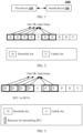
- FIG. 5 is a diagram of resource distribution of a rate match pattern.
- a slashed part is a resource corresponding to the rate match pattern, that is, the PDSCH does not occupy the resource in this part of area.
- the rate match pattern may be indicated by a bitmap (bitmap).
- the network device configures the rate match pattern for the terminal device by using a RateMatchPattern information element (information element, IE) in the radio resource control (radio resource control, RRC) signaling.
- FIG. 5 is used as an example.
- the network device may indicate a time domain position of the rate match pattern through symbolsInResourceBlock signaling in the RateMatchPattern IE, and indicate a frequency domain position of the rate match pattern through resourceBlocks signaling in the RateMatchPattern IE.
- symbolsInResourceBlock is a 14-bit bitmap
- resourceBlocks is a 275-bit bitmap.
- FIG. 5 is used as an example.
- a value of symbolsInResourceBlock is 00001111111000, indicating that the rate match pattern includes time domain symbols 4 to 10.
- a value of resourceBlocks is 0011110000...000 (275 bits, where "" indicates that all bits are 0s), indicating that the rate match pattern includes an RB 2 to an RB 5 in frequency domain.
- the network device may alternatively configure a rate match pattern through control resource set (controlResourceSet, CORESET) signaling of the RateMatchPattern IE in the RRC signaling.
- controlResourceSet controlResourceSet
- CORESET control resource set index
- the network device indicates a control resource set index (controlResourceSetId) through the controlResourceSet signaling, a corresponding CORESET is configured for the index, and the CORESET is configured by the network device by using a ControlResourceSet IE in the RRC signaling.
- the network device configures a frequency domain parameter for the CORESET through frequencyDomainResources signaling in the controlResourceSet signaling.
- the parameter is a 45-bit bitmap, and each bit indicates six RBs.
- the network device configures a time domain length, for example, seven symbols, for the CORESET through duration (duration) signaling.
- a specific time domain start location of the CORESET is determined by a search space set (search space set, SSS) corresponding to the CORESET.
- the network device configures an SSS for the terminal device by using a SearchSpace IE in the RRC signaling, and associates the SSS with a corresponding CORESET by using a controlResourceSetId in the SearchSpace IE.
- the network device may determine, in the SearchSpace IE through monitoringSymbolsWithinSlot signaling or the like, a time domain position of the SSS configured by the network device in one slot.
- FIG. 5 shows resource distribution of only one rate match pattern.
- the network device may configure two rate match pattern groups (rate match pattern groups) for the terminal device through the RRC signaling.
- Each rate match pattern group may include a maximum of eight rate match patterns, and each rate match pattern may be obtained by using the foregoing two methods.
- a finally reserved area is a union set of the plurality of rate match patterns.
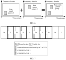
- FIG. 6 shows resource distribution of a rate match pattern group.
- rateMatchPatternGroup1 includes two rate match patterns: rateMatchPattern1 and rateMatchPattern2, and the two rate match patterns appear in a same slot.
- Each large rectangular box may be understood as one slot
- each small rectangular box filled with slashes may be understood as one rate match pattern
- rateMatchPatternGroup1 is a union set of the two rate match patterns.
- a transmit end device When mapping data to the time-frequency resource of the PDSCH, a transmit end device needs to avoid these reserved parts. Similarly, when receiving data, a receive end device also separately processes the data.
- the network device may explicitly indicate, by using the DCI, the rate match pattern group that needs to be avoided.
- the DCI includes a 2-bit rate matching indicator field, and the rate matching indicator field indicates rate match pattern groups avoided by all PDSCHs scheduled by using the DCI.
- '00' indicates that the PDSCH scheduled by using the DCI does not need to avoid any rate match pattern group
- '10' indicates that the PDSCH scheduled by using the DCI avoides a rate match pattern group 1
- '01' indicates that the PDSCH scheduled by using the DCI avoides a rate match pattern group 2
- '11' indicates that the PDSCH scheduled by using the DCI avoides a reserved resource of a union set of the rate match pattern group 1 and the rate match pattern group 2.
- a rate matching indicator field in the DCI format 1_1 indicates '01'
- a PDSCH indicated by the DCI does not cover the rate match pattern group 1.
- the PDSCH is not mapped to a resource area filled with the slashes.
- the rate matching indicator field takes effect on all PDSCHs indicated by the rate matching indicator field.
- One piece of DCI is used to schedule six PDSCHs, and a rate matching indicator field of the DCI is '01'. In other words, the six PDSCHs need to avoid resources shown on the right side of FIG. 6 .
- M is a positive integer less than L
- G is a positive integer greater than or equal to 2.
- An i th rate match pattern group in the L rate match pattern groups indicates an i th second resource
- the i th second resource is a time-frequency resource that is indicated by the control information and that cannot be occupied by the i th physical shared channel.
- the i th physical shared channel in the L physical shared channels occupies an i th third resource.
- the i th third resource is a resource other than an overlapping resource in the i th first resource
- the overlapping resource is an overlapping resource between the i th second resource and the i th first resource.
- a name of a message between devices or a name or the like of each parameter in the message is merely an example, and may alternatively be another name in a specific implementation. This is not specifically limited in embodiments of this application.
- a communication method 800 provided in an embodiment of this application includes the following steps.
- a first device sends first configuration information to a second device.
- the second device receives the first configuration information from the first device.
- the first configuration information is used to configure P rate match pattern groups, and P is a positive integer greater than 1.
- the first configuration information may be a PDSCH-config IE in RRC signaling.
- the first configuration information may be PUSCH-config information in the RRC signaling.
- S802 The first device sends control information to the second device.
- the second device receives the control information from the first device.
- Table 2 Row index PDSCH mapping type K 0 S L PDSCH mapping type K 0 S L PDSCH mapping type K 0 S L 1 Type A x 1 y 1 z 1 Type A x 2 y 2 z 2 Type A x 3 y 3 z 3 ...
- K 0 in Table 2 may be replaced with K 2 in a unit of slot, indicating a time offset of the PDSCH relative to the corresponding DCI.
- L first resources where L is a positive integer greater than 1.
- the first resource is described as follows: An i th first resource in the L first resources is a time-frequency resource allocated to an i th physical shared channel in the L physical shared channels, where i is any positive integer less than or equal to L.
- the control information is the DCI
- the DCI includes the TDRA field and an FDRA field.
- a resource of the first resource in time domain may include a time domain resource indicated by the TDRA field, and a resource of the first resource in frequency domain may include a frequency domain resource indicated by the FDRA field.
- An i th rate match pattern group in the L rate match pattern groups indicates an i th second resource
- the i th second resource is a time-frequency resource that is indicated by the control information and that cannot be occupied by the i th physical shared channel, where i is any positive integer less than or equal to L.
- any one of the L rate match pattern groups is at most one of the P rate match pattern groups.
- the at most one may be understood as that when the i th rate match pattern group in the L rate match pattern groups is not null, the rate match pattern group is one of the P rate match pattern groups. On the contrary, when the i th rate match pattern group in the L rate match pattern groups is null, the rate match pattern group does not exist.
- the i th rate match pattern group in the L rate match pattern groups is not null, that the i th rate match pattern group exists, and that the i th second resource exists express a same meaning, and that the i th rate match pattern group in the L rate match pattern groups is not null, that the i th rate match pattern group exists, and that the i th second resource exists may be replaced with each other.
- the i th rate match pattern group in the L rate match pattern groups is null
- that the i th rate match pattern group does not exist, and that the i th second resource does not exist express a same meaning
- a 1 st rate match pattern group in the L rate match pattern groups is a rate match pattern group corresponding to a PDSCH 1, and the rate match pattern group is null.
- a 2 nd rate match pattern group in the L rate match pattern groups is a rate match pattern group corresponding to a PDSCH 2, and the rate match pattern group is not null, and corresponds to the rate match pattern group 2 in the P rate match pattern groups.
- a 3 rd rate match pattern group in the L rate match pattern groups is a rate match pattern group corresponding to a PDSCH 3, and the rate match pattern group is not null, and corresponds to the rate match pattern group 1 in the P rate match pattern groups.
- a 4 th rate match pattern group in the L rate match pattern groups is a rate match pattern group corresponding to a PDSCH 4, and the rate match pattern group is not null, and corresponds to the rate match pattern group 2 in the P rate match pattern groups.
- a 5 th rate match pattern group in the L rate match pattern groups is a rate match pattern group corresponding to a PDSCH 5, and the rate match pattern group is null.
- a 6 th rate match pattern group in the L rate match pattern groups is a rate match pattern group corresponding to a PDSCH 6, and the rate match pattern group is null.
- the control information includes a first field.
- the first field includes G bits, and the G bits indicate the L rate match pattern groups.
- the G bits include a plurality of bit groups, and each of the plurality of bit groups indicates rate match pattern groups for a maximum of M physical shared channels.
- the M physical shared channels are a part of the L physical shared channels, and the rate match pattern groups indicated by each of the plurality of bit groups are a part of the L rate match pattern groups.
- M is a positive integer less than L
- G is a positive integer greater than or equal to 2.
- Each of the plurality of bit groups includes one or more of the G bits.
- control information is the DCI
- the first field is a rate matching indicator field
- G indicates a size (bit width) of the rate matching indicator field.
- bit group may alternatively be replaced with another description, for example, a bit set or a bit segment.
- bit group uses the bit group as an example for description, and should not be construed as a limitation on embodiments of this application.
- the M physical shared channels corresponding to the first bit group are a g th physical shared channel in the L physical shared channels.
- G is a positive integer greater than or equal to 2L
- g is any positive integer less than or equal to L
- X indicates a maximum quantity of physical shared channels that can be scheduled by using the control information.
- the (2*g-1) th bit in the G bits is a (2*g-1) th bit obtained through calculation starting from the MSB to the LSB in the G bits.
- the (2*g) th bit in the G bits is a (2*g) th bit obtained through calculation starting from the MSB to the LSB in the G bits.
- the (2*(X-L+g)-1) th bit in the G bits is a (2*(X-L+g)-1) th bit obtained through calculation starting from the MSB to the LSB in the G bits.
- the (2*(X-L+g)) th bit in the G bits is a (2*(X-L+g)) th bit obtained through calculation starting from the MSB to the LSB in the G bits.
- the first field includes 14 bits, and the bits are numbered from 1 to 14.
- the MSB is a bit numbered 1
- the LSB is a bit numbered 14.
- the (2*g-1) th bit in the G bits is a (2*g-1) th bit obtained through calculation starting from the LSB to the MSB in the G bits.
- the (2*g) th bit in the G bits is a (2*g) th bit obtained through calculation starting from the LSB to the MSB in the G bits.
- the (2*(X-L+g)-1) th bit in the G bits is a (2*(X-L+g)-1) th bit obtained through calculation starting from the LSB to the MSB in the G bits.
- the (2*(X-L+g)) th bit in the G bits is a (2*(X-L+g)) th bit obtained through calculation starting from the LSB to the MSB in the G bits.
- the 5 bits are counted from the MSB, and a 6 th bit and a 7 th bit (or described as bits numbered 6 and 7) obtained through calculation starting from the MSB are ignored by the second device, that is, do not indicate a rate match pattern group for any physical shared channel.
- the g th bit in the G bits is a g th bit obtained through calculation starting from the LSB to the MSB in the G bits.
- the (g+G-L) th bit in the G bits is a (g+G-L) th bit obtained through calculation starting from the LSB to the MSB in the G bits.
- every 1 bit in G bits starts to sequentially indicate a rate match pattern group of a different physical shared channel.
- a 2 nd bit obtained through calculation starting from the LSB to the MSB in the 7 bits indicates a rate match pattern group of a 2 nd physical shared channel (for example, denoted as the PDSCH 2) scheduled by using the control information.
- Other bits may be deduced by analogy. Details are not described again.
- each bit group (or described as each bit) in the first field indicates the rate match pattern group for the physical shared channel, so that the control information can flexibly indicate the rate match pattern groups for the different physical shared channels.
- X indicates the maximum quantity of physical shared channels that can be scheduled by using the control information.
- the G bits in the first field may indicate each physical shared channel that can be scheduled by using the control information.
- G may be any positive integer greater than or equal to X.
- a value of G may alternatively be configured by the first device.
- the first device Before performing S802, the first device further performs S804.
- S804 The first device sends third configuration information to the second device.
- the second device receives the third configuration information from the first device.
- the first value is 0 and the second value is 1.
- the rate match pattern group indicated by the first bit group does not exist. It may be understood that no resource reservation area needs to be removed from the actual transmission resource of the physical shared channel corresponding to the first bit group.
- the rate match pattern group indicated by the first bit group is the rate match pattern group 1. It may be understood that a resource reservation area of the rate match pattern group 1 needs to be removed from the actual transmission resource of the physical shared channel corresponding to the first bit group.
- the rate match pattern group indicated by the first bit group is the rate match pattern group 2. It may be understood that a resource reservation area of the rate match pattern group 2 needs to be removed from the actual transmission resource of the physical shared channel corresponding to the first bit group.
- the first value is 1 and the second value is 0.
- the rate match pattern group indicated by the first bit group does not exist. It may be understood that no resource reservation area needs to be removed from the actual transmission resource of the physical shared channel corresponding to the first bit group.
- the first bit group is used as an example, and the first bit group includes the g th bit in the G bits.
- the first bit group indicates the following two cases (following Case 3 and Case 4):
- the first value is 0 and the second value is 1.
- the rate match pattern group indicated by the first bit group is the rate match pattern group 2. It may be understood that a resource reservation area of the rate match pattern group 2 needs to be removed from the actual transmission resource of the physical shared channel corresponding to the first bit group.
- the rate match pattern group indicated by the first bit group is the rate match pattern group 1. It may be understood that a resource reservation area of the rate match pattern group 1 needs to be removed from the actual transmission resource of the physical shared channel corresponding to the first bit group.
- the rate match pattern group indicated by the first bit group is the rate match pattern group 2. It may be understood that a resource reservation area of the rate match pattern group 2 needs to be removed from the actual transmission resource of the physical shared channel corresponding to the first bit group.
- the g th bit in the G bits may be replaced with the (g+G-L) th bit in the G bits.
- the first bit group includes the (g+G-L) th bit in the G bits.
- each bit group (or described as each bit) in the first field indicates the rate match pattern group for the physical shared channel. This can flexibly indicate the rate match pattern groups for the different physical shared channels to some extent, and can reduce signaling overheads.
- Each of the plurality of bit groups includes one of the G bits.
- a value G of the first field is a fixed value.
- Each bit group corresponds to the maximum of M physical shared channels in the L physical shared channels, where M>1, and M ⁇ L. It may be understood that each of the plurality of bit groups indicates the rate match pattern groups for the maximum of M physical shared channels.
- N 1 is the positive integer
- the M physical shared channels corresponding to the first bit group are ((g-1)*V 1 +1) th to (g*V 1 ) th physical shared channels in the L physical shared channels.
- each of the first N 1 bits indicates rate match pattern groups for V 1 physical shared channels.
- different bits in the first N 1 bits correspond to different physical shared channels.
- the M physical shared channels corresponding to the first bit group are (N 1 *V 1 +(g-N 1 -1)*V 2 +1) th to (N 1 *V 1 +(g-N 1 -1)*V 2 +V 2 ) th physical shared channels in the L physical shared channels.
- each bit after an N 1 th bit in the G bits indicates rate match pattern groups for V 2 physical shared channels.
- the g th bit in the G bits is a g th bit obtained through calculation starting from the MSB to the LSB in the G bits.
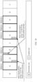
- a 1 st bit (for example, a bit numbered 1 in FIG. 13 ) obtained through calculation starting from the MSB to the LSB in the rate matching indicator field indicates a rate match pattern group of a 1 st PDSCH and a rate match pattern group of a 2 nd PDSCH (denoted as a PDSCH 1 and a PDSCH 2 in FIG. 13 ).
- a 2 nd bit (for example, a bit numbered 2 in FIG.
- a 4 th bit (for example, a bit numbered 4 in FIG. 13 ) obtained through calculation starting from the MSB to the LSB in the rate matching indicator field indicates a rate match pattern group of a 7 th PDSCH (denoted as a PDSCH 7 in FIG. 13 ).
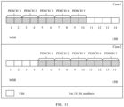
- a 1 st bit (for example, a bit numbered 1 in FIG. 15 ) obtained through calculation starting from the MSB to the LSB in the rate matching indicator field indicates a rate match pattern group of a 1 st PDSCH (denoted as a PDSCH 1 in FIG. 15 ).
- a 2 nd bit for example, a bit numbered 2 in FIG.
- the second configuration information may be configuration information, for example, rateMatchPatternSubgroup-r18 signaling, in PDSCH-config in the RRC signaling, and indicates the value of M.
- rateMatchPatternSubgroup-r18 signaling in PDSCH-config in the RRC signaling
- M indicates the value of M.
- the value of M is semi-statically configured by the network device through the RRC signaling.
- the disclosed systems, apparatuses, and methods may be implemented in other manners.
- the described apparatus embodiments are merely examples.
- division into the units is merely logical function division.
- a plurality of units or components may be combined or integrated into another system, or some features may be ignored or not performed.
- the displayed or discussed mutual couplings or direct couplings or communication connections may be implemented through some interfaces.
- the indirect couplings or communication connections between the apparatuses or units may be implemented in electronic, mechanical, or other forms.
- the units described as separate parts may or may not be physically separate, and parts displayed as units may or may not be physical units, may be located in one position, or may be distributed on a plurality of network units. Some or all of the units may be selected based on an actual requirement to achieve the objectives of the solutions of embodiments.
Landscapes
- Engineering & Computer Science (AREA)
- Signal Processing (AREA)
- Computer Networks & Wireless Communication (AREA)
- Mobile Radio Communication Systems (AREA)
- Time-Division Multiplex Systems (AREA)
Applications Claiming Priority (3)
| Application Number | Priority Date | Filing Date | Title |
|---|---|---|---|
| CN202211169675 | 2022-09-22 | ||
| CN202211303879.8A CN117749335A (zh) | 2022-09-22 | 2022-10-24 | 通信方法及装置 |
| PCT/CN2023/116551 WO2024060970A1 (fr) | 2022-09-22 | 2023-09-01 | Procédé et appareil de communication |
Publications (2)
| Publication Number | Publication Date |
|---|---|
| EP4580107A1 true EP4580107A1 (fr) | 2025-07-02 |
| EP4580107A4 EP4580107A4 (fr) | 2025-12-24 |
Family
ID=90281890
Family Applications (1)
| Application Number | Title | Priority Date | Filing Date |
|---|---|---|---|
| EP23867261.2A Pending EP4580107A4 (fr) | 2022-09-22 | 2023-09-01 | Procédé et appareil de communication |
Country Status (3)
| Country | Link |
|---|---|
| EP (1) | EP4580107A4 (fr) |
| CN (1) | CN117749335A (fr) |
| WO (1) | WO2024060970A1 (fr) |
Families Citing this family (1)
| Publication number | Priority date | Publication date | Assignee | Title |
|---|---|---|---|---|
| WO2026000377A1 (fr) * | 2024-06-28 | 2026-01-02 | Oppo广东移动通信有限公司 | Procédé d'adaptation de débit et dispositif de communication |
Family Cites Families (5)
| Publication number | Priority date | Publication date | Assignee | Title |
|---|---|---|---|---|
| CN110535604B (zh) * | 2019-03-29 | 2024-04-30 | 中兴通讯股份有限公司 | 一种速率匹配方法和装置 |
| EP3955668A4 (fr) * | 2019-08-27 | 2022-04-13 | Guangdong Oppo Mobile Telecommunications Corp., Ltd. | Procédé de communication sans fil, dispositif terminal et dispositif de réseau |
| US11711817B2 (en) * | 2020-04-10 | 2023-07-25 | Qualcomm Incorporated | Rate matching for a physical downlink shared channel (PDSCH) |
| CN113543328B (zh) * | 2020-04-17 | 2024-07-23 | 华为技术有限公司 | 一种通信方法和通信装置 |
| CN117581495A (zh) * | 2021-01-18 | 2024-02-20 | 欧芬诺有限责任公司 | 下行链路调度和混合自动重复请求反馈 |
-
2022
- 2022-10-24 CN CN202211303879.8A patent/CN117749335A/zh active Pending
-
2023
- 2023-09-01 EP EP23867261.2A patent/EP4580107A4/fr active Pending
- 2023-09-01 WO PCT/CN2023/116551 patent/WO2024060970A1/fr not_active Ceased
Also Published As
| Publication number | Publication date |
|---|---|
| CN117749335A (zh) | 2024-03-22 |
| EP4580107A4 (fr) | 2025-12-24 |
| WO2024060970A1 (fr) | 2024-03-28 |
Similar Documents
| Publication | Publication Date | Title |
|---|---|---|
| USRE50387E1 (en) | Determination of resource block groups in a user equipment bandwidth part | |
| US11778619B2 (en) | Communication method and apparatus, and computer storage medium | |
| EP3780468A1 (fr) | Procédé de détermination de paramètres, procédé de surveillance et appareil de communication | |
| EP3952168A1 (fr) | Procédé de transmission d'informations de renvoi de demande de répétition automatique hybride (harq) et appareil de communication | |
| US12016044B2 (en) | Data transmission method and communications apparatus | |
| EP3488650B1 (fr) | Noeud de réseau et dispositif utilisateur pour système de communication sans fil | |
| US20220386356A1 (en) | Method and device for transmitting/receiving control information in wireless communication system | |
| US20180192420A1 (en) | Method, apparatus and system | |
| CN116830728B (zh) | 资源确定方法及装置、通信设备、通信系统及介质 | |
| WO2024067617A1 (fr) | Procédé et appareil de configuration de ressources | |
| US12004228B2 (en) | Information transmission method, terminal device, and network device | |
| US20250344203A1 (en) | Reference signal transmission method and communication apparatus | |
| EP4429371A1 (fr) | Procédé d'indication de ressources et appareil de communication | |
| US20260067887A1 (en) | Transmission information determining method, configuration information sending method, terminal, and device | |
| CN112398592A (zh) | 反馈信息传输方法及通信装置 | |
| EP4615106A1 (fr) | Procédé de configuration de sous-bande et appareil de communication | |
| EP3833062B1 (fr) | Procédé et dispositif d'attribution de ressources dans un système tdd | |
| EP4580107A1 (fr) | Procédé et appareil de communication | |
| EP3397011A1 (fr) | Terminal, station de base et procédé de transmission de données | |
| US11533761B2 (en) | Information processing method and device | |
| CN114071720A (zh) | 资源确定的方法以及通信装置 | |
| EP4319401A1 (fr) | Procédé de transmission d'informations de commande de liaison descendante et dispositif associé | |
| WO2022102669A1 (fr) | Terminal | |
| EP3764709B1 (fr) | Procédé et dispositif de transmission d'informations | |
| EP4593499A1 (fr) | Procédé de transmission de liaison montante et appareil de communication |
Legal Events
| Date | Code | Title | Description |
|---|---|---|---|
| STAA | Information on the status of an ep patent application or granted ep patent |
Free format text: STATUS: THE INTERNATIONAL PUBLICATION HAS BEEN MADE |
|
| PUAI | Public reference made under article 153(3) epc to a published international application that has entered the european phase |
Free format text: ORIGINAL CODE: 0009012 |
|
| STAA | Information on the status of an ep patent application or granted ep patent |
Free format text: STATUS: REQUEST FOR EXAMINATION WAS MADE |
|
| 17P | Request for examination filed |
Effective date: 20250325 |
|
| AK | Designated contracting states |
Kind code of ref document: A1 Designated state(s): AL AT BE BG CH CY CZ DE DK EE ES FI FR GB GR HR HU IE IS IT LI LT LU LV MC ME MK MT NL NO PL PT RO RS SE SI SK SM TR |
|
| A4 | Supplementary search report drawn up and despatched |
Effective date: 20251126 |
|
| RIC1 | Information provided on ipc code assigned before grant |
Ipc: H04L 5/00 20060101AFI20251120BHEP Ipc: H04W 72/1263 20230101ALI20251120BHEP Ipc: H04W 72/232 20230101ALI20251120BHEP |
|
| DAV | Request for validation of the european patent (deleted) | ||
| DAX | Request for extension of the european patent (deleted) |