EP4580140A2 - Canal de commande de liaison montante physique (pucch) à étalement de la transformée de fourier discrète (dft-s) avec multiplexage d'utilisateur - Google Patents
Canal de commande de liaison montante physique (pucch) à étalement de la transformée de fourier discrète (dft-s) avec multiplexage d'utilisateur Download PDFInfo
- Publication number
- EP4580140A2 EP4580140A2 EP25174824.0A EP25174824A EP4580140A2 EP 4580140 A2 EP4580140 A2 EP 4580140A2 EP 25174824 A EP25174824 A EP 25174824A EP 4580140 A2 EP4580140 A2 EP 4580140A2
- Authority
- EP
- European Patent Office
- Prior art keywords
- block
- information symbols
- wireless communication
- communication device
- frequency
- Prior art date
- Legal status (The legal status is an assumption and is not a legal conclusion. Google has not performed a legal analysis and makes no representation as to the accuracy of the status listed.)
- Pending
Links
Images


Classifications
-
- H—ELECTRICITY
- H04—ELECTRIC COMMUNICATION TECHNIQUE
- H04J—MULTIPLEX COMMUNICATION
- H04J13/00—Code division multiplex systems
- H04J13/0003—Code application, i.e. aspects relating to how codes are applied to form multiplexed channels
-
- H—ELECTRICITY
- H04—ELECTRIC COMMUNICATION TECHNIQUE
- H04L—TRANSMISSION OF DIGITAL INFORMATION, e.g. TELEGRAPHIC COMMUNICATION
- H04L1/00—Arrangements for detecting or preventing errors in the information received
- H04L1/004—Arrangements for detecting or preventing errors in the information received by using forward error control
- H04L1/0056—Systems characterized by the type of code used
- H04L1/0064—Concatenated codes
-
- H—ELECTRICITY
- H04—ELECTRIC COMMUNICATION TECHNIQUE
- H04J—MULTIPLEX COMMUNICATION
- H04J13/00—Code division multiplex systems
- H04J13/0007—Code type
- H04J13/004—Orthogonal
-
- H—ELECTRICITY
- H04—ELECTRIC COMMUNICATION TECHNIQUE
- H04J—MULTIPLEX COMMUNICATION
- H04J13/00—Code division multiplex systems
- H04J13/0074—Code shifting or hopping
-
- H—ELECTRICITY
- H04—ELECTRIC COMMUNICATION TECHNIQUE
- H04J—MULTIPLEX COMMUNICATION
- H04J13/00—Code division multiplex systems
- H04J13/10—Code generation
- H04J13/12—Generation of orthogonal codes
-
- H—ELECTRICITY
- H04—ELECTRIC COMMUNICATION TECHNIQUE
- H04L—TRANSMISSION OF DIGITAL INFORMATION, e.g. TELEGRAPHIC COMMUNICATION
- H04L27/00—Modulated-carrier systems
- H04L27/26—Systems using multi-frequency codes
- H04L27/2601—Multicarrier modulation systems
- H04L27/2626—Arrangements specific to the transmitter only
- H04L27/2627—Modulators
- H04L27/2634—Inverse fast Fourier transform [IFFT] or inverse discrete Fourier transform [IDFT] modulators in combination with other circuits for modulation
- H04L27/2636—Inverse fast Fourier transform [IFFT] or inverse discrete Fourier transform [IDFT] modulators in combination with other circuits for modulation with FFT or DFT modulators, e.g. standard single-carrier frequency-division multiple access [SC-FDMA] transmitter or DFT spread orthogonal frequency division multiplexing [DFT-SOFDM]
-
- H—ELECTRICITY
- H04—ELECTRIC COMMUNICATION TECHNIQUE
- H04L—TRANSMISSION OF DIGITAL INFORMATION, e.g. TELEGRAPHIC COMMUNICATION
- H04L5/00—Arrangements affording multiple use of the transmission path
- H04L5/0001—Arrangements for dividing the transmission path
- H04L5/0014—Three-dimensional division
- H04L5/0016—Time-frequency-code
- H04L5/0019—Time-frequency-code in which one code is applied, as a temporal sequence, to all frequencies
-
- H—ELECTRICITY
- H04—ELECTRIC COMMUNICATION TECHNIQUE
- H04L—TRANSMISSION OF DIGITAL INFORMATION, e.g. TELEGRAPHIC COMMUNICATION
- H04L5/00—Arrangements affording multiple use of the transmission path
- H04L5/003—Arrangements for allocating sub-channels of the transmission path
- H04L5/0037—Inter-user or inter-terminal allocation
-
- H—ELECTRICITY
- H04—ELECTRIC COMMUNICATION TECHNIQUE
- H04L—TRANSMISSION OF DIGITAL INFORMATION, e.g. TELEGRAPHIC COMMUNICATION
- H04L5/00—Arrangements affording multiple use of the transmission path
- H04L5/003—Arrangements for allocating sub-channels of the transmission path
- H04L5/0048—Allocation of pilot signals, i.e. of signals known to the receiver
- H04L5/0051—Allocation of pilot signals, i.e. of signals known to the receiver of dedicated pilots, i.e. pilots destined for a single user or terminal
-
- H—ELECTRICITY
- H04—ELECTRIC COMMUNICATION TECHNIQUE
- H04L—TRANSMISSION OF DIGITAL INFORMATION, e.g. TELEGRAPHIC COMMUNICATION
- H04L5/00—Arrangements affording multiple use of the transmission path
- H04L5/003—Arrangements for allocating sub-channels of the transmission path
- H04L5/0053—Allocation of signalling, i.e. of overhead other than pilot signals
Definitions
- This application relates to wireless communication systems, and more particularly to improving user multiplexing with discrete Fourier transform (DFT) precoded frequency interlaces.
- DFT discrete Fourier transform
- a wireless multiple-access communications system may include a number of base stations (BSs), each simultaneously supporting communications for multiple communication devices, which may be otherwise known as user equipment (UE).
- BSs base stations
- UE user equipment
- NR next generation new radio
- LTE long term evolution
- NR is designed to provide a lower latency, a higher bandwidth or throughput, and a higher reliability than LTE.
- NR is designed to operate over a wide array of spectrum bands, for example, from low-frequency bands below about 1 gigahertz (GHz) and mid-frequency bands from about 1 GHz to about 6 GHz, to high-frequency bands such as millimeter wave (mmWave) bands.
- GHz gigahertz
- mmWave millimeter wave
- NR is also designed to operate across different spectrum types, from licensed spectrum to unlicensed and shared spectrum. Spectrum sharing enables operators to opportunistically aggregate spectrums to dynamically support high-bandwidth services. Spectrum sharing can extend the benefit of NR technologies to operating entities that may not have access to a licensed spectrum.
- PSD power spectral density
- ETSI European Telecommunications Standard Institute
- EN 301 893 V2.1.1 specifies various PSD limits for sub-6 GHz frequency bands
- ETSI draft document EN 302 567 V2.0.22 specifies a maximum equivalent isotropic radiated power (EIRP) and an EIRP density for 60 GHz frequency bands.
- EIRP maximum equivalent isotropic radiated power
- CBRS citizens broadband radio service
- different spectrums may have different PSD requirements and/or different bandwidth occupancy requirements.
- One approach to meeting the PSD requirement of a frequency spectrum and allowing a wireless communication device to transmit in the frequency spectrum at a full transmit power is to spread the frequency occupancy of a transmission signal over a wider bandwidth.
- the spreading of the frequency occupancy reduces the number of users that can be frequency-multiplexed in the frequency spectrum.
- a method of wireless communication includes identifying, by a first wireless communication device, a first block-spreading code from a set of block-spreading codes associated with user multiplexing; and communicating, by the first wireless communication device with a second wireless communication device using a frequency interlace in a frequency spectrum, a first communication signal including a first block of information symbols spread across a set of resource blocks (RBs) within the frequency interlace based on the first block-spreading code.
- RBs resource blocks
- an apparatus includes means for identifying a first block-spreading code from a set of block-spreading codes associated with user multiplexing; and means for communicating, with a first wireless communication device using a frequency interlace in a frequency spectrum, a first communication signal including a first block of information symbols spread across a set of resource blocks (RBs) within the frequency interlace based on the first block-spreading code.
- a first wireless communication device using a frequency interlace in a frequency spectrum, a first communication signal including a first block of information symbols spread across a set of resource blocks (RBs) within the frequency interlace based on the first block-spreading code.
- RBs resource blocks
- a computer-readable medium having program code recorded thereon includes code for causing a first wireless communication device to identify a first block-spreading code from a set of block-spreading codes associated with user multiplexing; and code for causing the first wireless communication device to communicate, with a second wireless communication device using a frequency interlace in a frequency spectrum, a first communication signal including a first block of information symbols spread across a set of resource blocks (RBs) within the frequency interlace based on the first block-spreading code.
- RBs resource blocks
- 3GPP 3rd Generation Partnership Project
- 3GPP long term evolution LTE
- UMTS universal mobile telecommunications system
- the 3GPP may define specifications for the next generation of mobile networks, mobile systems, and mobile devices.
- the present disclosure is concerned with the evolution of wireless technologies from LTE, 4G, 5G, NR, and beyond with shared access to wireless spectrum between networks using a collection of new and different radio access technologies or radio air interfaces.
- 5G networks contemplate diverse deployments, diverse spectrum, and diverse services and devices that may be implemented using an OFDM-based unified, air interface.
- further enhancements to LTE and LTE-A are considered in addition to development of the new radio technology for 5G NR networks.
- the 5G NR may be implemented to use optimized OFDM-based waveforms with scalable numerology and transmission time interval (TTI); having a common, flexible framework to efficiently multiplex services and features with a dynamic, low-latency time division duplex (TDD)/frequency division duplex (FDD) design; and with advanced wireless technologies, such as massive multiple input, multiple output (MIMO), robust millimeter wave (mmWave) transmissions, advanced channel coding, and device-centric mobility.
- TTI numerology and transmission time interval
- subcarrier spacing may occur with 15 kHz, for example over 5, 10, 20 MHz, and the like bandwidth (BW).
- BW bandwidth
- subcarrier spacing may occur with 30 kHz over 80/100 MHz BW.
- the subcarrier spacing may occur with 60 kHz over a 160 MHz BW.
- subcarrier spacing may occur with 120 kHz over a 500MHz BW.
- the scalable numerology of the 5G NR facilitates scalable TTI for diverse latency and quality of service (QoS) requirements. For example, shorter TTI may be used for low latency and high reliability, while longer TTI may be used for higher spectral efficiency.
- QoS quality of service
- 5G NR also contemplates a self-contained integrated subframe design with uplink/downlink scheduling information, data, and acknowledgement in the same subframe.
- the self-contained integrated subframe supports communications in unlicensed or contention-based shared spectrum, adaptive uplink/downlink that may be flexibly configured on a per-cell basis to dynamically switch between uplink and downlink to meet the current traffic needs.
- an aspect disclosed herein may be implemented independently of any other aspects and that two or more of these aspects may be combined in various ways.
- an apparatus may be implemented or a method may be practiced using any number of the aspects set forth herein.
- such an apparatus may be implemented or such a method may be practiced using other structure, functionality, or structure and functionality in addition to or other than one or more of the aspects set forth herein.
- a method may be implemented as part of a system, device, apparatus, and/or as instructions stored on a computer readable medium for execution on a processor or computer.
- an aspect may comprise at least one element of a claim.
- a BS may assign multiple UEs to transmit uplink information on the same frequency interlace.
- the BS may assign different UEs with different block-spreading codes that are orthogonal to each other.
- the block-spreading codes can be orthogonal cover codes (OCCs).
- a UE may generate a block of information symbols carrying uplink information (e.g., control information).
- the UE may apply block-spreading to the information symbols using an assigned block-spreading code.
- the UE may perform DFT spreading or DFT precoding on the block of spread information symbols to produce a frequency signal.
- the UE may map the frequency signal to the frequency interlace.
- the block-spreading, the DFT, and the frequency interlace mapping operations in effect spread the block of information across the entire DFT precoded frequency interlace.
- the UE may further perform time-domain spreading across multiple time-domain symbols (e.g., single carrier-frequency division multiplexing (SC-FDM) symbols).
- SC-FDM single carrier-frequency division multiplexing
- the UE may further perform code-hopping across multiple time-domain symbols. While the disclosed embodiments are described in the context of physical uplink control channel (PUCCH) transmissions in a shared spectrum or an unlicensed spectrum, the disclose embodiments can be applied to any channel signal transmissions, such as physical uplink shared channel (PUSCH) transmissions, in any spectrum.
- PUCCH physical uplink control channel
- PUSCH physical uplink shared channel
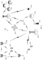
- FIG. 1 illustrates a wireless communication network 100 according to some embodiments of the present disclosure.
- the network 100 may be a 5G network.
- the network 100 includes a number of base stations (BSs) 105 and other network entities.
- a BS 105 may be a station that communicates with UEs 115 and may also be referred to as an evolved node B (eNB), a next generation eNB (gNB), an access point, and the like.
- eNB evolved node B
- gNB next generation eNB
- Each BS 105 may provide communication coverage for a particular geographic area.
- the term "cell" can refer to this particular geographic coverage area of a BS 105 and/or a BS subsystem serving the coverage area, depending on the context in which the term is used.
- a BS 105 may provide communication coverage for a macro cell or a small cell, such as a pico cell or a femto cell, and/or other types of cell.
- a macro cell generally covers a relatively large geographic area (e.g., several kilometers in radius) and may allow unrestricted access by UEs with service subscriptions with the network provider.
- a small cell such as a pico cell, would generally cover a relatively smaller geographic area and may allow unrestricted access by UEs with service subscriptions with the network provider.
- a small cell such as a femto cell, would also generally cover a relatively small geographic area (e.g., a home) and, in addition to unrestricted access, may also provide restricted access by UEs having an association with the femto cell (e.g., UEs in a closed subscriber group (CSG), UEs for users in the home, and the like).
- a BS for a macro cell may be referred to as a macro BS.
- a BS for a small cell may be referred to as a small cell BS, a pico BS, a femto BS or a home BS. In the example shown in FIG.
- the BSs 105d and 105e may be regular macro BSs, while the BSs 105a-105c may be macro BSs enabled with one of three dimension (3D), full dimension (FD), or massive MIMO.
- the BSs 105a-105c may take advantage of their higher dimension MIMO capabilities to exploit 3D beamforming in both elevation and azimuth beamforming to increase coverage and capacity.
- the BS 105f may be a small cell BS which may be a home node or portable access point.
- a BS 105 may support one or multiple (e.g., two, three, four, and the like) cells.
- the network 100 may support synchronous or asynchronous operation.
- the BSs may have similar frame timing, and transmissions from different BSs may be approximately aligned in time.
- the BSs may have different frame timing, and transmissions from different BSs may not be aligned in time.
- the UEs 115 are dispersed throughout the wireless network 100, and each UE 115 may be stationary or mobile.
- a UE 115 may also be referred to as a terminal, a mobile station, a subscriber unit, a station, or the like.
- a UE 115 may be a cellular phone, a personal digital assistant (PDA), a wireless modem, a wireless communication device, a handheld device, a tablet computer, a laptop computer, a cordless phone, a wireless local loop (WLL) station, or the like.
- PDA personal digital assistant
- WLL wireless local loop
- a UE 115 may be a device that includes a Universal Integrated Circuit Card (UICC).
- a UE may be a device that does not include a UICC.
- UICC Universal Integrated Circuit Card
- the UEs 115 that do not include UICCs may also be referred to as IoT devices or internet of everything (IoE) devices.
- the UEs 115a-115d are examples of mobile smart phone-type devices accessing network 100
- a UE 115 may also be a machine specifically configured for connected communication, including machine type communication (MTC), enhanced MTC (eMTC), narrowband IoT (NB-IoT) and the like.
- MTC machine type communication
- eMTC enhanced MTC
- NB-IoT narrowband IoT
- the UEs 115e-115k are examples of various machines configured for communication that access the network 100.
- a UE 115 may be able to communicate with any type of the BSs, whether macro BS, small cell, or the like. In FIG.
- a lightning bolt (e.g., communication links) indicates wireless transmissions between a UE 115 and a serving BS 105, which is a BS designated to serve the UE 115 on the downlink and/or uplink, or desired transmission between BSs, and backhaul transmissions between BSs.
- UE 115f e.g., a thermometer
- UE 115g e.g., smart meter
- UE 115h e.g., wearable device
- the network 100 may also provide additional network efficiency through dynamic, low-latency TDD/FDD communications, such as in a vehicle-to-vehicle (V2V)
- V2V vehicle-to-vehicle
- the network 100 utilizes OFDM-based waveforms for communications.
- An OFDM-based system may partition the system BW into multiple (K) orthogonal subcarriers, which are also commonly referred to as subcarriers, tones, bins, or the like. Each subcarrier may be modulated with data.
- the subcarrier spacing between adjacent subcarriers may be fixed, and the total number of subcarriers (K) may be dependent on the system BW.
- the system BW may also be partitioned into subbands. In other instances, the subcarrier spacing and/or the duration of TTIs may be scalable.
- the BSs 105 can assign or schedule transmission resources (e.g., in the form of time-frequency resource blocks (RB)) for downlink (DL) and uplink (UL) transmissions in the network 100.
- DL refers to the transmission direction from a BS 105 to a UE 115
- UL refers to the transmission direction from a UE 115 to a BS 105.
- the communication can be in the form of radio frames.
- a radio frame may be divided into a plurality of subframes, for example, about 10.
- Each subframe can be divided into slots, for example, about 2.
- Each slot may be further divided into mini-slots.
- simultaneous UL and DL transmissions may occur in different frequency bands.
- each subframe includes a UL subframe in a UL frequency band and a DL subframe in a DL frequency band.
- UL and DL transmissions occur at different time periods using the same frequency band.
- a subset of the subframes (e.g., DL subframes) in a radio frame may be used for DL transmissions and another subset of the subframes (e.g., UL subframes) in the radio frame may be used for UL transmissions.
- each DL or UL subframe may have pre-defined regions for transmissions of reference signals, control information, and data.
- Reference signals are predetermined signals that facilitate the communications between the BSs 105 and the UEs 115.
- a reference signal can have a particular pilot pattern or structure, where pilot tones may span across an operational BW or frequency band, each positioned at a pre-defined time and a pre-defined frequency.
- a BS 105 may transmit cell specific reference signals (CRSs) and/or channel state information - reference signals (CSI-RSs) to enable a UE 115 to estimate a DL channel.
- CRSs cell specific reference signals
- CSI-RSs channel state information - reference signals
- a UE 115 may transmit sounding reference signals (SRSs) to enable a BS 105 to estimate a UL channel.
- Control information may include resource assignments and protocol controls.
- Data may include protocol data and/or operational data.
- the BSs 105 and the UEs 115 may communicate using self-contained subframes.
- a self-contained subframe may include a portion for DL communication and a portion for UL communication.
- a self-contained subframe can be DL-centric or UL-centric.
- a DL-centric subframe may include a longer duration for DL communication than for UL communication.
- a UL-centric subframe may include a longer duration for UL communication than for UL communication.
- the network 100 may be an NR network deployed over a licensed spectrum.
- the BSs 105 can transmit synchronization signals (e.g., including a primary synchronization signal (PSS) and a secondary synchronization signal (SSS)) in the network 100 to facilitate synchronization.
- the BSs 105 can broadcast system information associated with the network 100 (e.g., including a master information block (MIB), remaining minimum system information (RMSI), and other system information (OSI)) to facilitate initial network access.
- MIB master information block
- RMSI remaining minimum system information
- OSI system information
- the BSs 105 may broadcast the PSS, the SSS, and/or the MIB in the form of synchronization signal blocks (SSBs) over a physical broadcast channel (PBCH) and may broadcast the RMSI and/or the OSI over a physical downlink shared channel (PDSCH).
- PBCH physical broadcast channel
- PDSCH physical downlink shared channel
- the UE 115 may receive a MIB.
- the MIB may include system information for initial network access and scheduling information for RMSI and/or OSI.
- the UE 115 may receive RMSI and/or OSI.
- the RMSI and/or OSI may include radio resource control (RRC) information related to random access channel (RACH) procedures, paging, control resource set (CORESET) for physical downlink control channel (PDCCH) monitoring, physical uplink control channel (PUCCH), physical uplink shared channel (PUSCH), power control, SRS, and cell barring.
- RRC radio resource control
- the UE 115 and the BS 105 can enter a normal operation stage, where operational data may be exchanged.
- the BS 105 may schedule the UE 115 for UL and/or DL communications.
- the BS 105 may transmit UL and/or DL scheduling grants to the UE 115 via a PDCCH.
- the BS 105 may transmit a DL communication signal to the UE 115 via a PDSCH according to a DL scheduling grant.
- the UE 115 may transmit a UL communication signal to the BS 105 via a PUSCH and/or PUCCH according to a UL scheduling grant.
- the network 100 may operate over a system BW or a component carrier (CC) BW.
- the network 100 may partition the system BW into multiple BWPs (e.g., portions).
- a BS 105 may dynamically assign a UE 115 to operate over a certain BWP (e.g., a certain portion of the system BW).
- the assigned BWP may be referred to as the active BWP.
- the UE 115 may monitor the active BWP for signaling information from the BS 105.
- the BS 105 may schedule the UE 115 for UL or DL communications in the active BWP.
- a BS 105 may assign a pair of BWPs within the CC to a UE 115 for UL and DL communications.
- the BWP pair may include one BWP for UL communications and one BWP for DL communications.
- the UE 115 may transmit UL control information to a BS 105 over a PUCCH.
- the BS 105 may schedule the UE 115 for UL transmissions based on the received UL control information.
- Some examples of UL control information may include scheduling requests (SRs), channel state information (CSI)-reports, and/or hybrid automatic repeat request (HARQ) feedbacks (e.g., acknowledgements (ACKs) and/or not-ACKs).
- a BS 105 may assign multiple UEs 115 with the same PUCCH resources (e.g., time-frequency resources) using multiplexing schemes.
- the network 100 may operate over various frequency bands, for example, in frequency ranges between about 2 GHz to above 60 GHz.
- Different frequency bands may have different PSD requirements.
- certain frequency bands may have a maximum allowable PSD level of about 10 decibel-milliwatts per megahertz (dBm/MHz) to about 17 dBm/MHz.
- a transmitter having a full power of about 23 dBm may or may not be able to utilize the full power for a signal transmission depending on the signal frequency bandwidth.
- a transmitter e.g., the BSs 105 and the UEs 115
- a transmitter may transmit a signal over multiple narrow frequency bands spaced apart from each other in a frequency bandwidth at a higher power than transmitting the signal over contiguous frequencies.
- a BS 105 may configure UEs 115 to communicate PUCCH information using frequency interlaces, where the PUCCH information may be distributed across the entire frequency interlace to increase bandwidth occupancy, for example, to meet certain PSD requirements.
- the BS may assign multiple UEs 115 on the same frequency interlace by using DFT precoding with block-spreading OCCs as described in greater detail herein.
- FIG. 2 illustrates a resource configuration scheme with frequency interlaces according to some embodiments of the present disclosure.
- the x-axis represents time in some constant units and the y-axis represents frequency in some constant units.
- the scheme 200 may be employed by BSs such as the BSs 105 and UEs such as the UEs 115 in a network such as the network 100 to communicate with each other over a frequency spectrum 202.
- the frequency spectrum 202 may have a bandwidth of about 10 megahertz (MHz) or about 20 MHz and a subcarrier spacing (SCS) of about 15 kilohertz (kHz), about 30 kHz, or about 60 kHz.
- the frequency spectrum 202 may be located at any suitable frequencies. In some embodiments, the frequency spectrum 202 may be located at about 3.5 GHz, 6 GHz, or 60 GHz.
- the scheme 200 allocates resources in units of frequency interlaces 208.
- the frequency interlaces are shown as 208 I(0) to 208 I(M-1) , where M is a positive integer.
- Each frequency interlace 208 may include K plurality of RBs 210 evenly spaced over the frequency spectrum 202, where K is a positive integer.
- the RBs 210 in a particular frequency interlace 208 I(i) are spaced apart from each other by at least one other RB 210, where i may vary between 0 and M-1.
- the values K and M may vary based on several factors, such as the bandwidth, the subcarrier spacing (SCS), and/or the PSD limitation of the frequency spectrum 202, as described in greater detail herein. In some instances, the value K may also vary for different interlaces.
- a group of M localized RBs 210 forms a cluster 204.
- the frequency interlaces 208 I(0) to 208 (M-1) form K clusters 204 C(0) to 204 C(K-1) .
- Each RB 210 may span about twelve contiguous subcarriers 212 in frequency and a time period 214.
- the subcarriers 212 are indexed from 0 to 11.
- the time period 214 may span any suitable number of OFDM symbols 216.
- the time period 214 may correspond to one transmission time interval (TTI), which may include about fourteen OFDM symbols 216.
- TTI transmission time interval
- the number of clusters 204 or the value of K may be dependent on the amount of frequency distribution required to maintain a certain PSD level.
- the frequency spectrum 202 may have a bandwidth of about 20 MHz and each subcarrier 212 may span about 15 kHz in frequency.
- an allocation may include one frequency interlace 208 having ten distributed or equally spaced RBs 210. Compared to an allocation with a single RB or ten localized RBs, the interlaced allocation with the ten distributed RBs 210 allows a UE to transmit at a higher power while maintaining the same PSD level.
- the frequency spectrum 202 may have a bandwidth of about 10 MHz and each subcarrier 212 may span about 15 kHz in frequency.
- an allocation may include one frequency interlace 208 having ten distributed RBs 210. The interlaced allocation with the ten distributed RBs may allow for better power utilization than an allocation with a single RB or ten localized RBs at the same PSD level
- the frequency spectrum 202 may have a bandwidth of about 20 MHz and each subcarrier 212 may span about 30 kHz in frequency.
- an allocation may include one frequency interlace 208 having ten distributed RBs 210. The interlaced allocation with the ten distributed RBs may allow for better power utilization than an allocation with a single RB or ten localized RBs at the same PSD level.
- the frequency spectrum 202 may have a maximum allowable PSD level of about 13 dBm/MHz and a transmitter (e.g., the UEs 115) may have a power amplifier (PA) capable of transmitting at about 23 dBm.
- a transmitter e.g., the UEs 115
- PA power amplifier
- Distributing frequency occupancy of an allocation into five clusters 204 may allow the transmitter to transmit at about 20 dBm (e.g., with a power boost of about 7 dB) while maintaining a PSD level of about 13 dBm/MHz.
- Distributing frequency occupancy of an allocation into ten clusters 204 may allow the transmitter to transmit at a full power of about 23 dBm (e.g., with a power boost of about 10 dB) while maintaining a PSD level of about 13 dBm/MHz.
- a full power of about 23 dBm e.g., with a power boost of about 10 dB
- PSD level e.g., with a power boost of about 10 dB
- the use of frequency interlacing can provide better power utilization.
- the scheme 200 may be applied to a PUCCH to provide a power boost at a transmitter (e.g., the UEs 115).
- a transmitter e.g., the UEs 115.
- one RB 210 may be sufficient to carry UCI of a particular PUCCH format signal.
- a UE may extend the frequency occupancy of the PUCCH signal from one RB 210 to K RBs 210 by transmitting the PUCCH signal using one frequency interlace 208.
- interlaced waveforms can improve link budget for better coverage under PSD limit as it allows UE to transmit at a higher power level.
- each PUCCH occupies a greater number of RBs compared to a non-interlaced allocation. For example, the number of UEs that can be multiplexed over the frequency spectrum 202 for PUCCH signal transmissions may be reduced by a factor of about K if each UE only required one RB when there were no constraints on PSD.
- FIG. 3A illustrates a transmission scheme 300 with pre-DFT-OCC spreading according to some embodiments of the present disclosure.
- the scheme 300 may be employed by BSs such as the BSs 105 and UEs such as the UEs 115 in a network such as the network 100 for PUCCH transmissions.
- the scheme 300 can be used in conjunction with the scheme 200.
- FIG. 3A illustrates three information symbols 310 shown as D0, D1, and D2 spread by a length-4 OCC 320 shown as C0, C1, C2, C3 across a cluster 204 prior to a DFT spreading.
- FIG. 4A illustrates a transmission scheme 400 with pre-DFT-OCC spreading according to some embodiments of the present disclosure.
- the scheme 400 may be employed by BSs such as the BSs 105 and UEs such as the UEs 115 in a network such as the network 100 for a PUCCH transmission.
- the scheme 400 can be used in conjunction with the scheme 200.
- the scheme 400 is described using a similar configuration as the scheme 300, where three information symbols 310 are spread by a length-4 OCC 320 shown as C0, C1, C2, C3 across a cluster 204 prior to a DFT spreading.
- the scheme 400 is described using the frequency interlace structure in FIG. 2 , and may use the same reference numerals as in FIG. 2 for simplicity sake.
- the scheme 400 performs the pre-DFT-OCC spreading using block repetitions instead of symbol repetitions.
- the UE spreads the information symbols 310 as a block 410 by the OCC 320 to form a sequence of block-spread symbols 430.
- the block-spread symbols 430 can be represented by [D0 ⁇ C0, D1 ⁇ C0, D2 ⁇ C0, D0 ⁇ C1, D1 ⁇ C1, D2 ⁇ C1, D0 ⁇ C2, D1 ⁇ C2, D2 ⁇ C2, D0 ⁇ C3, D1 ⁇ C3, D2 ⁇ C3 ⁇ .
- the block-spread symbols can be further spread by a DFT 340 and the DFT output can be mapped to an RB 210 of an assigned frequency interlace 208 I(0) within a cluster 204 c(0) as shown in the in plot 450.
- the UE may further generate information symbols D3, D4, and D5 (e.g., the information symbols 310) and repeat the scheme 400 to spread the information symbols D3, D4, and D5 as a block using the OCC 320 across a portion of the frequency interlace 208 I(0) within another cluster 204 (e.g., 204 c(1) ). Accordingly, the spreading by the OCC 320 produces a sequence ⁇ D3 ⁇ C0, D4 ⁇ C0, D5 ⁇ C0,D3 ⁇ C1, D4 ⁇ C1, D5 ⁇ C1, D3 ⁇ C2, D4 ⁇ C2, D5 ⁇ C2, D3 ⁇ C3, D4 ⁇ C3, D5 ⁇ C3 ⁇
- FIG. 4B is similar to FIG. 4A , but shows additional aspects of the scheme 400 (e.g., pre-DFT-OCC spreading for more information symbols 310).
- pre-DFT-OCC spreading can be applied to information symbols 310 including D0, D1, D2, D3, D4, and D5.
- the pre-DFT-OCC spreading based on block repetitions in time and spreading by the OCC 320 (shown by the dotted-line box) as discussed above in FIG. 4A can be applied to the information symbols 310.
- the DFT 340 is applied to the sequence of spread symbols [D0 ⁇ C0, D1 ⁇ C0, D2 ⁇ C0, D0 ⁇ C1, D1 ⁇ C1, D2 ⁇ C1, D0 ⁇ C2, D1 ⁇ C2, D2 ⁇ C2, D0 ⁇ C3, D1 ⁇ C3, D2 ⁇ C3, D3 ⁇ C0, D4 ⁇ C0, D5 ⁇ C0,D3 ⁇ C1, D4 ⁇ C1, D5 ⁇ C1, D3 ⁇ C2, D4 ⁇ C2, D5 ⁇ C2, D3 ⁇ C3, D4 ⁇ C3, D5 ⁇ C3 ⁇ .
- the sequence of spread symbols can be represented as ⁇ D0 ⁇ C0, D1 ⁇ C0, D2 ⁇ C0, ..., DN ⁇ C3 ⁇ and the DFT 340 is applied across the sequence of spread symbols.
- the output of the DFT 340 is mapped to RBs 210 of the frequency interlace 208 I(0) as shown in the plot 450.
- the subsequent DFT spreading may not preserve the code-division multiplexing (CDM) orthogonality provided by the OCCs.
- the DFT output may include tones or resource elements (REs) (e.g., the subcarriers 212) that carry useful signals from two or more UEs, causing interference among the UEs and degrading performance.
- REs resource elements
- additional receiver processing e.g., including a joint equalizer across UEs
- the complexity of the receive may increase, and thus may not be desirable.
- the present disclosure provides techniques to perform pre-DFT-OCC for an increased user multiplexing capacity, but without the complex receiver processing or degraded performance as in the schemes 300 and 400.
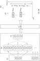
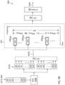
- FIG. 5 is a block diagram of an exemplary UE 500 according to embodiments of the present disclosure.
- the UE 500 may be a UE 115 as discussed above.
- the UE 500 may include a processor 502, a memory 504, a pre-DFT-OCC-based communication module 508, a transceiver 510 including a modem subsystem 512 and a radio frequency (RF) unit 514, and one or more antennas 516.
- RF radio frequency
- the memory 504 may include a cache memory (e.g., a cache memory of the processor 502), random access memory (RAM), magnetoresistive RAM (MRAM), read-only memory (ROM), programmable read-only memory (PROM), erasable programmable read only memory (EPROM), electrically erasable programmable read only memory (EEPROM), flash memory, solid state memory device, hard disk drives, other forms of volatile and non-volatile memory, or a combination of different types of memory.
- the memory 504 includes a non-transitory computer-readable medium.
- the memory 504 may store instructions 506.
- the instructions 506 may include instructions that, when executed by the processor 502, cause the processor 502 to perform the operations described herein with reference to the UEs 115 in connection with embodiments of the present disclosure. Instructions 506 may also be referred to as code.
- the terms "instructions” and “code” should be interpreted broadly to include any type of computer-readable statement(s). For example, the terms “instructions” and “code” may refer to one or more programs, routines, sub-routines, functions, procedures, etc. "Instructions" and “code” may include a single computer-readable statement or many computer-readable statements.
- the pre-DFT-OCC-based communication module 508 may be implemented via hardware, software, or combinations thereof.
- the pre-DFT-OCC-based communication module 508 may be implemented as a processor, circuit, and/or instructions 506 stored in the memory 504 and executed by the processor 502.
- the pre-DFT-OCC-based communication module 508 may be used for various aspects of the present disclosure.
- the pre-DFT-OCC-based communication module 508 is configured to receive an allocation for a transmission on a frequency interlace (e.g., the frequency interlace 208) and an OCC (e.g., the OCCs 320) from a BS (e.g., the BSs 105), generate information symbols (e.g., the information symbols 310), perform a block-spreading of the information symbols across the entire frequency interlace using the OCC, perform a DFT spreading after the OCC block-spreading, map the DFT output to the frequency interlace, transmit a signal including the pre-DFT-OCC block-spread information symbols to the BS, as described in greater detail herein.
- a frequency interlace e.g., the frequency interlace 208
- an OCC e.g., the OCCs 320
- information symbols e.g., the information symbols 310
- perform a block-spreading of the information symbols across the entire frequency interlace using the OCC perform a D
- the transceiver 510 may include the modem subsystem 512 and the RF unit 514.
- the transceiver 510 can be configured to communicate bi-directionally with other devices, such as the BSs 105.
- the modem subsystem 512 may be configured to modulate and/or encode the data from the memory 504, and/or the pre-DFT-OCC-based communication module 508 according to a modulation and coding scheme (MCS), e.g., a low-density parity check (LDPC) coding scheme, a turbo coding scheme, a convolutional coding scheme, a digital beamforming scheme, etc.
- MCS modulation and coding scheme
- LDPC low-density parity check
- the RF unit 514 may provide the modulated and/or processed data, e.g. data packets (or, more generally, data messages that may contain one or more data packets and other information), to the antennas 516 for transmission to one or more other devices.
- the antennas 516 may further receive data messages transmitted from other devices.
- the antennas 516 may provide the received data messages for processing and/or demodulation at the transceiver 510.
- the antennas 516 may include multiple antennas of similar or different designs in order to sustain multiple transmission links.
- the RF unit 514 may configure the antennas 516.
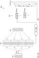
- FIG. 6 is a block diagram of an exemplary BS 600 according to embodiments of the present disclosure.
- the BS 600 may be a BS 105 as discussed above.
- the BS 600 may include a processor 602, a memory 604, a pre-DFT-OCC-based communication module 608, a transceiver 610 including a modem subsystem 612 and a RF unit 614, and one or more antennas 616. These elements may be in direct or indirect communication with each other, for example via one or more buses.
- the processor 602 may have various features as a specific-type processor. For example, these may include a CPU, a DSP, an ASIC, a controller, a FPGA device, another hardware device, a firmware device, or any combination thereof configured to perform the operations described herein.
- the processor 602 may also be implemented as a combination of computing devices, e.g., a combination of a DSP and a microprocessor, a plurality of microprocessors, one or more microprocessors in conjunction with a DSP core, or any other such configuration.
- the pre-DFT-OCC-based communication module 608 may be implemented via hardware, software, or combinations thereof.
- the pre-DFT-OCC-based communication module 608 may be implemented as a processor, circuit, and/or instructions 606 stored in the memory 604 and executed by the processor 602.
- the pre-DFT-OCC-based communication module 608 may be used for various aspects of the present disclosure.
- the transceiver 610 may include the modem subsystem 612 and the RF unit 614.
- the transceiver 610 can be configured to communicate bi-directionally with other devices, such as the UEs 115 and/or another core network element.
- the modem subsystem 612 may be configured to modulate and/or encode data according to a MCS, e.g., a LDPC coding scheme, a turbo coding scheme, a convolutional coding scheme, a digital beamforming scheme, etc.
- the RF unit 614 may be configured to process (e.g., perform analog to digital conversion or digital to analog conversion, etc.) modulated/encoded data from the modem subsystem 612 (on outbound transmissions) or of transmissions originating from another source such as a UE 115 or 500.
- the RF unit 614 may be further configured to perform analog beamforming in conjunction with the digital beamforming.
- the modem subsystem 612 and/or the RF unit 614 may be separate devices that are coupled together at the BS 105 to enable the BS 105 to communicate with other devices.
- the RF unit 614 may provide the modulated and/or processed data, e.g. data packets (or, more generally, data messages that may contain one or more data packets and other information), to the antennas 616 for transmission to one or more other devices. This may include, for example, transmission of information to complete attachment to a network and communication with a camped UE 115 or 500 according to embodiments of the present disclosure.
- the antennas 616 may further receive data messages transmitted from other devices and provide the received data messages for processing and/or demodulation at the transceiver 610.
- the antennas 616 may include multiple antennas of similar or different designs in order to sustain multiple transmission links.
- the UE A generates information symbols 702 shown as a0, a1, a2, a3, a4, and a5 (e.g., the information symbols 310).
- the UE A applies an OCC 710a to block-spread the information symbols 702 in a time domain to form a sequence of block-spread symbols 712a.
- the UE A performs DFT spreading to the block-spread symbols 712a by applying a DFT 720 (e.g., the DFT 340). Based on the FFT property described in greater detail below, the DFT output 722a, denoted as DFT( S 0 ), is located on even tones (e.g., the subcarriers 212) as shown by the pattern-filled boxes.
- a DFT 720 e.g., the DFT 340
- the DFT output 722a denoted as DFT( S 0 ) is located on even tones (e.g., the subcarriers 212) as shown by the pattern-filled boxes.
- the UE A maps the DFT output 722a to an assigned RB (e.g., RB 210) and performs an inverse fast Fourier transform (IFFT) 730 to transform the DFT output 722a into a time domain signal, which may be referred as an SC-FDM symbol or a DFT-spreading-OFDM (DFT-s-OFDM) symbol. Accordingly, the time-domain signal may be referred to as a SC-FDM waveform signal or a DFT-s-OFDM waveform signal.
- the UE A applies a cyclic prefix (CP) add operation 740 to the time domain signal.
- the CP add operation 740 copies an end portion of the time domain signal to the beginning of the time domain signal.
- the UE A transmits the CP-added signal (e.g., an output signal 742a) to the BS.
- CP-added signal e.g., an output signal 742a
- the UE B generates information symbols 704 shown as b0, b1, b2, b3, b4, and b5 (e.g., the information symbols 310).
- the UE B applies an OCC 710b to block-spread the information symbols 704 to form a sequence of block-spread symbols 712b.
- the UE B performs DFT spreading to the block-spread symbols 712b by applying a DFT 720. Based on the FFT property as described in greater detail below, the DFT output 722b, denoted as DFT( S 1 ), is located on odd tones (e.g., the subcarriers 212) as shown by the pattern-filled boxes.
- the UE B maps the DFT output 722b to the same RB that is assigned to the UE A. Subsequently, the UE B applies an IFFT 730, followed by a CP add operation 740 to produce an output signal 742b.
- the UE B transmits the output signal 742b to the BS.
- the DFT output 722a includes non-zero values in odd tones only.
- the pre-DFT-OCC user multiplexing is equivalent to comb-based (e.g., FDM) user multiplexing as described in greater detail herein.
- FIG. 8A illustrates a user multiplexing scheme 800 using FDM according to some embodiments of the present disclosure.
- the scheme 800 uses a substantially similar transmission chain as the scheme 700, but without the pre-DFT-OCC spreading as in the scheme 700.
- a UE A generates information symbols 702 shown as a0, a1, a2, a3, a4, and a5.
- the UE A applies a DFT 720 to the information symbols 702.
- the UE A maps the DFT output 822a to even tones (e.g., subcarriers 212) within an assigned RB (e.g., the RB 210) to form a frequency signal 824a.
- the UE A applies an IFFT 730, followed by a CP add operation 740 to produce an output signal 842a.
- a UE B generates information symbols 704 shown as b0, b1, b2, b3, b4, and b5.
- the UE B applies a DFT 720 to the information symbols 704.
- the UE B maps the DFT output 822b to odd tones in the same RB that is assigned to the UE A to form a frequency signal 824b.
- the UE B applies an IFFT 730, followed by a CP add operation 740 to produce an output signal 842b.
- the pre-DFT-OCC spreading followed by the DFT spreading in the scheme 700 produce a similar orthogonal transmission structure among UEs as the FDM in the scheme 800.
- FIGS. 9A and 9B collectively illustrate a scheme 900 for multiplexing multiple users on a DFT precoded frequency interlace.
- the scheme 900 may be employed by BSs such as the BSs 105 and 600 and UEs such as the UEs 115 and 500 in a network such as the network 100.
- the scheme 900 is substantially similar to the scheme 700.
- the scheme 900 multiplexes a UE A and a UE B on a same frequency interlace 208 including a set of distributed RBs 210.
- the scheme 900 applies OCC block-spreading across the set of distributed RBs in the entire frequency interlace 208.
- the scheme 900 is described using the frequency interlace structure in FIG. 2 , and may use the same reference numerals as in FIG. 2 for simplicity sake.
- FIG. 9A illustrates a transmission scheme implemented by the UE A for multiplexing the UE A and the UE B on a DFT precoded interlace according to some embodiments of the disclosure.
- the UE A generates information symbols 902 shown as a0 to a59 (e.g., the information symbols 310, 702, and 704).
- the UE A applies the OCC 710a to block-spread the information symbols 902 to form a sequence of block-spread symbols 912a.
- the UE A applies a DFT 720 to the block-spread symbols 912a for a DFT spreading.
- the UE A performs a frequency interlace mapping 924 to map the DFT output 922a to a frequency interlace 208 I(0) , for example, based on an allocation from the BS.
- the DFT output 922a includes non-zero values in even tones (e.g., the subcarriers 212) only. Subsequently, the UE A applies an IFFT 730 and a CP add operation 740 as in the scheme 700 to generate an output signal 944a for transmission.
- FIG. 9B illustrates a transmission scheme implemented by the UE B for multiplexing the UE A and the UE B on a DFT precoded interlace according to some embodiments of the disclosure.
- the UE B generates information symbols 904 shown as b0 to b59 (e.g., the information symbols 310, 702, and 704).
- the UE B applies the OCC 710b to block-spread the information symbols 904 to form a sequence of block-spread symbols 912b.
- the DFT output 922b includes non-zero values in odd tones only. Subsequently, the UE B applies an IFFT 730 and CP add operation 740 generate an output signal 944b for transmission.
- FIG. 10 illustrates a receive processing scheme 1000 for a DFT precoded interlace according to some embodiments of the present disclosure.
- the scheme 1000 may be employed by BSs such as the BSs 105 and 600 and UEs such as the UEs 115 and 500 in a network such as the network 100.
- the scheme 1000 may be implemented by a receiver receiving a signal 1002 transmitted by a transmitter on a frequency interlace (e.g., the frequency interlace 208 I(0) ) using a pre-DFT-OCC as described in the scheme 900.
- a frequency interlace e.g., the frequency interlace 208 I(0)
- the scheme 1000 includes a CP discard unit 1010, an FFT unit 1020, a frequency interlace demapper 1030, a subcarrier demapper 1040, an inverse DFT (IDFT) unit 1050, and a data recovery unit 1060.
- CP discard unit 1010 an FFT unit 1020, a frequency interlace demapper 1030, a subcarrier demapper 1040, an inverse DFT (IDFT) unit 1050, and a data recovery unit 1060.
- IDFT inverse DFT
- the subcarrier demapper 1040 is coupled to the frequency interlace demapper 1030 and configured to extract subcarriers (e.g., the subcarriers 212) from the set of extracted RBs (e.g., the frequency signal 1032) based on the OCC that the transmitter used for the transmission of the received signal 1002.
- the extracted subcarriers form a frequency signal 1042.
- the subcarrier demapper 1040 extracts the even subcarriers from the set of extracted RBs. In other words, the subcarrier demapper 1040 forms a frequency signal 1042 from the extracted even subcarriers.
- the subcarrier demapper 1040 extracts the odd subcarriers from the set of extracted RBs. In other words, the subcarrier demapper 1040 forms a frequency signal 1042 from the extracted odd subcarriers.
- the IDFT unit 1050 is coupled to the subcarrier demapper 1040 and configured to perform an inverse DFT on the frequency signal 1042 to produce a time signal 1052.
- the data recovery unit 1060 is coupled to the IDFT unit 1050 and configured to recovery the original information transmitted by the transmitter from the time signal 1052.
- the data recovery operations may include time and/or frequency equalization, demodulation, and/or decoding.
- the subcarrier demapper 1040 extracts the useful subcarriers corresponding to non-zero values of the DFT output (e.g., the DFT output 722a, 722b, 922a, and 922b) at the transmitter for data recovery processing and may discard or ignore other subcarriers corresponding to zero values (e.g., that does not carry useful information) of the DFT output at the transmitter.
- the DFT output e.g., the DFT output 722a, 722b, 922a, and 922b
- the subcarrier demapper 1040 may extract the useful tones and the DFT of size equal to the number of useful subcarriers is performed. In another implementation, the subcarrier demapper 1040 may extract all tones of the interlace including non-useful subcarriers and OCC despreading may be performed at the data recovery unit 1060 post DFT.
- the DFT size in this case equals to the number of subcarriers (useful + not useful) on the corresponding interlace.
- FIG. 11 illustrates a user multiplexing scheme 1100 that applies time-domain OCC across multiple SC-FDM symbols according to some embodiments of the present disclosure.
- the x-axes represent time in some constant units and the y-axes represent frequency in some constant units.
- the scheme 1100 may be employed by BSs such as the BSs 105 and 600 and UEs such as the UEs 115 and 500 in a network such as the network 100.
- the scheme 1100 can be used in conjunction with the scheme 900.
- the scheme 1110 can be applied after the scheme 900.
- a BS may further multiplex transmission of a UE A and a UE B by configuring the UE A and the UE B to perform time-domain spreading using an OCC 1110a and an OCC 1110b, respectively.
- the UE A generates an output signal 1102a (e.g., an SC-FDM symbol) carrying information (e.g., the information symbols 310, 702, 704, 902, and 904) mapped to a certain frequency interlace (e.g., the frequency interlace 208 I(0) ), for example, using the scheme 900.
- the signal 1102a may correspond to the output signal 944a.
- the UE A applies the OCC 1110a to the signal 1102a to produce a time symbol 1112a(0) and a time symbol 1112a(1).
- the UE A may multiply the signal 1102a by C0 of the OCC 1110a to produce the symbol 1112a(0) and multiply the signal 1102a by C1 of the OCC 1110a to produce the symbol 1112a(1).
- the output signal 1102a is spread across two time symbols 1112a(0) and 1112a(1) (e.g., SC-FDM symbols) by the OCC 1110a.
- the UE B generates an output signal 1102b (e.g., an SC-FDM symbol) carrying information (e.g., the information symbols 310, 712a, 712b, 912a, and 912b) mapped to the same frequency interlace (e.g., the frequency interlace 208 I(0) ) as the one used by the UE A, for example, using the scheme 900.
- the signal 1102b may correspond to the output signal 944b.
- the UE B applies the OCC 1110b to the signal 1102b to produce a time symbol 1112b(0) and a time symbol 1112b(1)..
- the BS may configure the UE A with a code-hop pattern, where an OCC 1210 is applied to a first symbol at time T0 and an OCC 1220 is applied to a next symbol at time T1.
- the BS may configure the UE B with a code-hop pattern different than the UE A code-hop pattern, where the OCC 1220 is applied to a first symbol at time T0 and the OCC 1210 applied to a next symbol at time T1.
- the schemes 900, 1000, 1100, and 1200 are described in the context of multiplexing two UEs (e.g., a UE A and a UE B) on a frequency interlace (e.g., the frequency interlaces 208) with OCCs (e.g., the OCCs 710a, 710b, 1110a, 1110b, and 1210, 1220) and of length 2, the schemes 900, 1000, 1100, 1200 may be applied to multiplex any suitable number of UEs (e.g., about 3, 4, or 6) on a frequency interlace and may vary the code length of the OCCs accordingly.
- a frequency interlace e.g., the frequency interlaces 208
- OCCs e.g., the OCCs 710a, 710b, 1110a, 1110b, and 1210, 1220
- the schemes 900, 1000, 1100, 1200 may be applied to multiplex any suitable number of UEs (e.g., about 3, 4, or
- a wireless communication device such as the UE 115 and the UE 500, may utilize one or more components, such as the processor 502, the memory 504, the pre-DFT-OCC-based communication module 508, the transceiver 510, and the one or more antennas 516, to execute the steps of method 1300.
- the method 1300 may employ similar mechanisms as in the schemes 700, 900, 1000, 1100, and 1200 described with respect to FIGS. 7 , 9 , 10 , 11 , and 12 , respectively.
- the method 1300 includes a number of enumerated steps, but embodiments of the method 1300 may include additional steps before, after, and in between the enumerated steps. In some embodiments, one or more of the enumerated steps may be omitted or performed in a different order.
- the method 1300 includes identifying, by a first wireless communication device, a first block-spreading code from a set of block-spreading codes associated with user multiplexing.
- the set of block-spreading codes may be similar to the OCCs 710a and 710b or the OCCs 1210 and 1220.
- the first wireless communication device may correspond to a BS and the second wireless communication device may correspond to a UE. In such an embodiment, the first wireless communication device may further transmit a configuration to the second wireless communication device indicating the identified first block-spreading code.
- the first wireless communication device may correspond to a UE and the second wireless communication device may correspond to a BS.
- the first wireless communication device may further receive a configuration from the second wireless communication device indicating the identified first block-spreading code.
- the first wireless communication may identify the first block-spreading code based on the received configuration.
- the first block of information symbols is carried by a first set of subcarriers (e.g., the subcarriers 212) interlaced with a second set of subcarriers (e.g., the subcarriers 212) in the set of RBs (e.g., the RBs 210).
- the first block-spreading code is ⁇ 1, 1 ⁇
- the first set of subcarriers may correspond to even subcarriers in the set of RBs.
- the first block-spreading code is ⁇ 1, 1 ⁇
- the first set of subcarriers may correspond to odd subcarriers in the set of RBs.
- the first block-spreading code may have a length of 4 or 6 and the first set of subcarriers may correspond to every fourth subcarrier or every sixth subcarrier, respectively, in the set of RBs.
- the first wireless communication device may communicate the first communication signal by transmitting, to the second wireless communication device, the first communication signal including the first block of information symbols carried by the first set of subcarriers.
- the first wireless communication device further generates the first communication signal by block-spreading the first block of information symbols based on the first block-spreading code to generate a first block of spread information symbols (e.g., the block-spread information symbols 912a, 912b, 1212a, 1212b, 1222a, and 1222b).
- the first wireless communication device performs a DFT (e.g., the DFTs 340 and 720) on the first block of spread information symbols to generate a frequency signal (e.g., the DFT outputs 922a and 922b).
- the first wireless communication device maps the frequency signal to the set of resource blocks (e.g., the frequency interlace mapping 924), wherein non-zero values of the frequency signal are located at the first set of subcarriers.
- the first block-spreading code includes at least a first code (e.g., C0 of the OCC 710a or 710b) and a second code (e.g., C1 of the OCC 710a or 710b). Each of the first code and the second code may be referred to as a code symbol.
- the first wireless communication device block-spreads the first block of information symbols by applying the first code to the first block of information symbols to generate a first block of coded information symbols and applying the second code to the first block of information symbols to generate a second block of coded information symbols.
- the first wireless communication device generates the first block of spread information symbols (e.g., the symbols 912a or 912b) based on at least the first block of coded information symbols and the second block of coded information symbols, for example, by concatenating the first and second blocks.
- the first block of spread information symbols e.g., the symbols 912a or 912b
- the first wireless communication device may communicate the first communication signal by receiving, from the second wireless communication device, the first communication signal including the first block of information symbols carried by the first set of subcarriers.
- the first wireless communication device further performs an IDFT (e.g., the IDFT 1050) on the received first communication signal (e.g. the received signal 1002) based on the first set of subcarriers to recover the first block of information symbols, for example, using similar mechanisms as described in the scheme 1000.
- an IDFT e.g., the IDFT 1050
- the first wireless communication device identifies a second block-spreading code from the set of block-spreading codes.
- the wireless communication device communicates, with a third wireless communication device different from the second wireless communication device, a second communication signal concurrent with the first communication signal, the second communication signal including a second block of information symbols spread across the frequency interlace based on the second block-spreading code.
- the second block of information symbols is carried by the second set of subcarriers.
- the first wireless communication device corresponds to a BS
- the second wireless communication device corresponds to a UE A
- the third wireless communication device corresponds to a UE B.
- the first wireless communication device identifies the first block-spreading code by applying a code-hopping pattern to the set of block-spreading codes, for example, using the scheme 1200.
- Information and signals may be represented using any of a variety of different technologies and techniques.
- data, instructions, commands, information, signals, bits, symbols, and chips that may be referenced throughout the above description may be represented by voltages, currents, electromagnetic waves, magnetic fields or particles, optical fields or particles, or any combination thereof.
- a general-purpose processor may be a microprocessor, but in the alternative, the processor may be any conventional processor, controller, microcontroller, or state machine.
- a processor may also be implemented as a combination of computing devices (e.g., a combination of a DSP and a microprocessor, multiple microprocessors, one or more microprocessors in conjunction with a DSP core, or any other such configuration).
- the functions described herein may be implemented in hardware, software executed by a processor, firmware, or any combination thereof. If implemented in software executed by a processor, the functions may be stored on or transmitted over as one or more instructions or code on a computer-readable medium. Other examples and implementations are within the scope of the disclosure and appended claims. For example, due to the nature of software, functions described above can be implemented using software executed by a processor, hardware, firmware, hardwiring, or combinations of any of these. Features implementing functions may also be physically located at various positions, including being distributed such that portions of functions are implemented at different physical locations.
- the set of block-spreading codes includes orthogonal cover codes (OCCs).
- OOCs orthogonal cover codes
- the first block of information symbols is carried by a first set of subcarriers interlaced with a second set of subcarriers in the set of RBs.
- the communicating includes transmitting, by the first wireless communication device to the second wireless communication device, the first communication signal including the first block of information symbols carried by the first set of subcarriers.
- the method further comprises generating, by the first wireless communication device, the first communication signal by block-spreading the first block of information symbols based on the first block-spreading code to generate a first block of spread information symbols; performing a discrete Fourier transform (DFT) on the first block of spread information symbols to generate a frequency signal; and mapping the frequency signal to the set of RBs, wherein non-zero values of the frequency signal are located at the first set of subcarriers.
- DFT discrete Fourier transform
- the first block-spreading code includes at least a first code and a second code
- the block-spreading the first block of information symbols includes applying the first code to the first block of information symbols to generate a first block of coded information symbols; applying the second code to the first block of information symbols to generate a second block of coded information symbols; and generating the first block of spread information symbols based on at least the first block of coded information symbols and the second block of coded information symbols.
- the communicating includes receiving, by the first wireless communication device from the second wireless communication device, the first communication signal including the first block of information symbols carried by the first set of subcarriers.
- the method further comprises performing, by the first wireless communication device, an inverse discrete Fourier transform (IDFT) on the received first communication signal based on the first set of subcarriers to recover the first block of information symbols.
- the method further comprises identifying, by the first wireless communication device, a second block-spreading code from the set of block-spreading codes; and communicating, by the first wireless communication device with a third wireless communication device, a second communication signal concurrent with the first communication signal, the second communication signal including a second block of information symbols spread across the frequency interlace based on the second block-spreading code, wherein the second block of information symbols is carried by the second set of subcarriers, and wherein the third wireless communication device is different from the second wireless communication device.
- IDFT inverse discrete Fourier transform
- the communicating is further based on a time-domain spreading code.
- the identifying includes applying, by the first wireless communication device, a code-hopping pattern to the set of block-spreading codes.
- the first block of information symbols are modulation symbols including uplink control channel information.
- FIG. 1 For embodiments of the present disclosure, include an apparatus comprising a processor configured to identify a first block-spreading code from a set of block-spreading codes associated with user multiplexing; and a transceiver configured to communicate, with a first wireless communication device using a frequency interlace in a frequency spectrum, a first communication signal including a first block of information symbols spread across a set of resource blocks (RBs) within the frequency interlace based on the first block-spreading code.
- RBs resource blocks
- the set of block-spreading codes includes orthogonal cover codes (OCCs).
- OOCs orthogonal cover codes
- the first block of information symbols is carried by a first set of subcarriers interlaced with a second set of subcarriers in the set of RBs.
- the transceiver is further configured to communicate the first communication signal by transmitting, to the first wireless communication device, the first communication signal including the first block of information symbols carried by the first set of subcarriers.
- the processor is further configured to generate the first communication signal by block-spreading the first block of information symbols based on the first block-spreading code to generate a first block of spread information symbols; performing a discrete Fourier Transform (DFT) on the first block of spread information symbols to generate a frequency signal; and mapping the frequency signal to the set of RBs, wherein non-zero values of the frequency signal are located at the first set of subcarriers.
- DFT discrete Fourier Transform
- the first block-spreading code includes at least a first code and a second code
- the processor is further configured to block-spread the first block of information symbols by applying the first code to the first block of information symbols to generate a first block of coded information symbols; applying the second code to the first block of information symbols to generate a second block of coded information symbols; and generating the first block of spread information symbols based on at least the first block of coded information symbols and the second block of coded information symbols.
- the transceiver is further configured to communicate the first communication signal by receiving, from the first wireless communication device, the first communication signal including the first block of information symbols carried by the first set of subcarriers.
- the processor is further configured to perform an inverse discrete Fourier transform (IDFT) on the received first communication signal based on the first set of subcarriers to recover the first block of information symbols.
- IDFT inverse discrete Fourier transform
- the processor is further configured to identify a second block-spreading code from the set of block-spreading codes, and the transceiver is further configured to communicate, with a second wireless communication device, a second communication signal concurrent with the first communication signal, the second communication signal including a second block of information symbols spread across the frequency interlace based on the second block-spreading code, wherein the second block of information symbols is carried by the second set of subcarriers, and wherein the second wireless communication device is different from the first wireless communication device.
- IDFT inverse discrete Fourier transform
- the first communication signal is further communicated based on a time-domain spreading code.
- the processor is further configured to identify the first block-spreading code by applying a code-hopping pattern to the set of block-spreading codes.
- the first block of information symbols are modulation symbols including uplink control channel information.
- FIG. 1 For embodiments of the present disclosure, include a computer-readable medium having program code recorded thereon, the program code comprising code for causing a first wireless communication device to identify a first block-spreading code from a set of block-spreading codes associated with user multiplexing; and code for causing the first wireless communication device to communicate, with a second wireless communication device using a frequency interlace in a frequency spectrum, a first communication signal including a first block of information symbols spread across a set of resource blocks (RBs) within the frequency interlace based on the first block-spreading code.
- RBs resource blocks
- the set of block-spreading codes includes orthogonal cover codes (OCCs).
- OOCs orthogonal cover codes
- the first block of information symbols is carried by a first set of subcarriers interlaced with a second set of subcarriers in the set of RBs.
- the code for causing the first wireless communication device to communicate first communication signal is further configured to transmit, to the second wireless communication device, the first communication signal including the first block of information symbols carried by the first set of subcarriers.
- the computer-readable medium further comprises code for causing the first wireless communication device to generate the first communication signal by block-spreading the first block of information symbols based on the first block-spreading code to generate a first block of spread information symbols; performing a discrete Fourier transform (DFT) on the first block of spread information symbols to generate a frequency signal; and mapping the frequency signal to the set of RBs, wherein non-zero values of the frequency signal are located at the first set of subcarriers.
- DFT discrete Fourier transform
- the first block-spreading code includes at least a first code and a second code
- the code for causing the first wireless communication device to block-spread the first block of information symbols is further configured to apply the first code to the first block of information symbols to generate a first block of coded information symbols; apply the second code to the first block of information symbols to generate a second block of coded information symbols; and generate the first block of spread information symbols based on at least the first block of coded information symbols and the second block of coded information symbols.
- the code for causing the first wireless communication device to communicate first communication signal is further configured to receive, rom the second wireless communication device, the first communication signal including the first block of information symbols carried by the first set of subcarriers.
- the computer-readable medium further comprises code for causing the first wireless communication device to perform an inverse discrete Fourier transform (IDFT) on the received first communication signal based on the first set of subcarriers to recover the first block of information symbols.
- IDFT inverse discrete Fourier transform
- the computer-readable medium further comprises code for causing the first wireless communication device to identify a second block-spreading code from the set of block-spreading codes; and code for causing the first wireless communication device to communicate, with a third wireless communication device, a second communication signal concurrent with the first communication signal, the second communication signal including a second block of information symbols spread across the frequency interlace based on the second block-spreading code, wherein the second block of information symbols is carried by the second set of subcarriers, and wherein the third wireless communication device is different from the second wireless communication device.
- the code for causing the first wireless communication device to communicate the first communication signal is further configured to communicate the first communication signal based on a time-domain spreading code.
- the code for causing the first wireless communication device to identify the first block-spreading code is further configured to apply a code-hopping pattern to the set of block-spreading codes.
- the first block of information symbols are modulation symbols including uplink control channel information.
- the apparatus further comprises means for generating the first communication signal by block-spreading the first block of information symbols based on the first block-spreading code to generate a first block of spread information symbols; performing a discrete Fourier transform (DFT) on the first block of spread information symbols to generate a frequency signal; and mapping the frequency signal to the set of RBs, wherein non-zero values of the frequency signal are located at the first set of subcarriers.
- DFT discrete Fourier transform
- the first block-spreading code includes at least a first code and a second code
- the means for generating the first communication signal is further configured to apply the first code to the first block of information symbols to generate a first block of coded information symbols; apply the second code to the first block of information symbols to generate a second block of coded information symbols; and generate the first block of spread information symbols based on at least the first block of coded information symbols and the second block of coded information symbols.
- the means for communicating the first communication signal is further configured to receive, rom the first wireless communication device, the first communication signal including the first block of information symbols carried by the first set of subcarriers.
- the communicating the first communication signal may include: receiving, by the first wireless communication device from the second wireless communication device, the first communication signal based on the first block-spreading code; and the method may further comprise:
- the identifying may include: applying, by the first wireless communication device, a code-hopping pattern to the set of block-spreading codes.
- the first block of information symbols may be modulation symbols including uplink control channel information.
- an apparatus comprising:
- a non-transitory computer-readable medium having program code recorded thereon, the program code comprising:
- the first block-spreading code may be an orthogonal cover code (OCC) including at least a first code and a second code
- OCC orthogonal cover code
- the non-transitory computer-readable medium may further comprise: code for causing the first wireless communication device to generate the first communication signal by:
- the code for causing the first wireless communication device to communicate the first communication signal may be further configured to: receive, from the first wireless communication device, the first communication signal based on the first block-spreading code; and the non-transitory computer-readable medium may further comprise:
Landscapes
- Engineering & Computer Science (AREA)
- Signal Processing (AREA)
- Computer Networks & Wireless Communication (AREA)
- Physics & Mathematics (AREA)
- Discrete Mathematics (AREA)
- General Physics & Mathematics (AREA)
- Mathematical Physics (AREA)
- Mobile Radio Communication Systems (AREA)
Applications Claiming Priority (4)
| Application Number | Priority Date | Filing Date | Title |
|---|---|---|---|
| IN201841034335 | 2018-09-12 | ||
| US16/566,676 US11283547B2 (en) | 2018-09-12 | 2019-09-10 | Discrete Fourier transform-spread (DFT-S) based interlace physical uplink control channel (PUCCH) with user multiplexing |
| PCT/US2019/050640 WO2020056018A1 (fr) | 2018-09-12 | 2019-09-11 | Canal de commande de liaison montante physique (pucch) à étalement de la transformée de fourier discrète (dft-s) avec multiplexage d'utilisateur |
| EP19773697.8A EP3850769B1 (fr) | 2018-09-12 | 2019-09-11 | Canal de commande de liaison montante physique (pucch) à étalement de la transformée de fourier discrète (dft-s) avec multiplexage d'utilisateur |
Related Parent Applications (2)
| Application Number | Title | Priority Date | Filing Date |
|---|---|---|---|
| EP19773697.8A Division EP3850769B1 (fr) | 2018-09-12 | 2019-09-11 | Canal de commande de liaison montante physique (pucch) à étalement de la transformée de fourier discrète (dft-s) avec multiplexage d'utilisateur |
| EP19773697.8A Division-Into EP3850769B1 (fr) | 2018-09-12 | 2019-09-11 | Canal de commande de liaison montante physique (pucch) à étalement de la transformée de fourier discrète (dft-s) avec multiplexage d'utilisateur |
Publications (2)
| Publication Number | Publication Date |
|---|---|
| EP4580140A2 true EP4580140A2 (fr) | 2025-07-02 |
| EP4580140A3 EP4580140A3 (fr) | 2025-08-20 |
Family
ID=69720185
Family Applications (2)
| Application Number | Title | Priority Date | Filing Date |
|---|---|---|---|
| EP19773697.8A Active EP3850769B1 (fr) | 2018-09-12 | 2019-09-11 | Canal de commande de liaison montante physique (pucch) à étalement de la transformée de fourier discrète (dft-s) avec multiplexage d'utilisateur |
| EP25174824.0A Pending EP4580140A3 (fr) | 2018-09-12 | 2019-09-11 | Canal de commande de liaison montante physique (pucch) à étalement de la transformée de fourier discrète (dft-s) avec multiplexage d'utilisateur |
Family Applications Before (1)
| Application Number | Title | Priority Date | Filing Date |
|---|---|---|---|
| EP19773697.8A Active EP3850769B1 (fr) | 2018-09-12 | 2019-09-11 | Canal de commande de liaison montante physique (pucch) à étalement de la transformée de fourier discrète (dft-s) avec multiplexage d'utilisateur |
Country Status (4)
| Country | Link |
|---|---|
| US (3) | US11283547B2 (fr) |
| EP (2) | EP3850769B1 (fr) |
| CN (2) | CN112997426B (fr) |
| WO (1) | WO2020056018A1 (fr) |
Families Citing this family (6)
| Publication number | Priority date | Publication date | Assignee | Title |
|---|---|---|---|---|
| US11283547B2 (en) | 2018-09-12 | 2022-03-22 | Qualcomm Incorporated | Discrete Fourier transform-spread (DFT-S) based interlace physical uplink control channel (PUCCH) with user multiplexing |
| US12003445B2 (en) | 2020-09-29 | 2024-06-04 | Qualcomm Incorporated | Multiple user (MU) support for reference signal (RS) and data multiplexing on shared uplink (UL) resources(s) |
| US11452131B2 (en) * | 2020-12-08 | 2022-09-20 | Charter Communications Operating, Llc | Methods and apparatus for managing uplink resource grants in wireless networks |
| WO2024107165A1 (fr) * | 2022-11-14 | 2024-05-23 | Altiostar Networks, Inc. | Récepteur côté réseau pour recevoir des signaux transmis à grande vitesse |
| US20250055747A1 (en) * | 2023-08-07 | 2025-02-13 | Qualcomm Incorporated | Frequency domain orthogonal cover code based uplink shared channel multiplexing |
| WO2025040236A1 (fr) * | 2023-08-18 | 2025-02-27 | Telefonaktiebolaget Lm Ericsson (Publ) | Formation de faisceau entrelacée pour transmissions limitées à densité spectrale de puissance (dsp) |
Family Cites Families (5)
| Publication number | Priority date | Publication date | Assignee | Title |
|---|---|---|---|---|
| KR101782645B1 (ko) * | 2010-01-17 | 2017-09-28 | 엘지전자 주식회사 | 무선 통신 시스템에서 상향링크 제어 정보 전송 방법 및 장치 |
| US8638880B2 (en) * | 2010-01-18 | 2014-01-28 | Telefonaktiebolaget Lm Ericsson (Publ) | Radio base station and user equipment and methods therein |
| ES3013564T3 (en) * | 2015-12-07 | 2025-04-14 | Ericsson Telefon Ab L M | Uplink control channel configuration for unlicensed carriers |
| JP7018127B2 (ja) * | 2017-11-03 | 2022-02-09 | エルジー エレクトロニクス インコーポレイティド | 無線通信システムにおいて複数のスロットベースのロングpucchを送受信する方法及びその装置 |
| US11283547B2 (en) | 2018-09-12 | 2022-03-22 | Qualcomm Incorporated | Discrete Fourier transform-spread (DFT-S) based interlace physical uplink control channel (PUCCH) with user multiplexing |
-
2019
- 2019-09-10 US US16/566,676 patent/US11283547B2/en active Active
- 2019-09-11 WO PCT/US2019/050640 patent/WO2020056018A1/fr not_active Ceased
- 2019-09-11 CN CN201980058156.6A patent/CN112997426B/zh active Active
- 2019-09-11 EP EP19773697.8A patent/EP3850769B1/fr active Active
- 2019-09-11 CN CN202411953731.8A patent/CN119995773A/zh active Pending
- 2019-09-11 EP EP25174824.0A patent/EP4580140A3/fr active Pending
-
2022
- 2022-02-15 US US17/651,087 patent/US12057938B2/en active Active
-
2024
- 2024-06-21 US US18/751,149 patent/US12587313B2/en active Active
Also Published As
| Publication number | Publication date |
|---|---|
| US20240430036A1 (en) | 2024-12-26 |
| US11283547B2 (en) | 2022-03-22 |
| CN112997426A (zh) | 2021-06-18 |
| EP3850769B1 (fr) | 2025-07-02 |
| US12587313B2 (en) | 2026-03-24 |
| WO2020056018A1 (fr) | 2020-03-19 |
| US12057938B2 (en) | 2024-08-06 |
| EP3850769A1 (fr) | 2021-07-21 |
| EP4580140A3 (fr) | 2025-08-20 |
| CN112997426B (zh) | 2024-12-27 |
| CN119995773A (zh) | 2025-05-13 |
| US20200083986A1 (en) | 2020-03-12 |
| US20220173832A1 (en) | 2022-06-02 |
Similar Documents
| Publication | Publication Date | Title |
|---|---|---|
| US11855819B2 (en) | Waveform multiplexing in millimeter wave band | |
| EP4011162B1 (fr) | Conception de canal de commande de liaison montante physique (pucch) et de signal de référence pour nouvelle radio-sans licence (nr-u) | |
| CN114365570B (zh) | 用于新无线电未许可(nr-u)中的侧行链路的波形设计 | |
| EP3996461B1 (fr) | Configuration de partie de largeur de bande (bwp) pour l'accès à une sous-bande dans la nouvelle radio sans licence (nr-u) | |
| US12587313B2 (en) | Discrete fourier transform-spread (DFT-S) based interlace physical uplink control channel (PUCCH) with user multiplexing | |
| US11153781B2 (en) | Variable cyclic prefix (CP) within a transmission slot in millimeter wave band | |
| EP3756399B1 (fr) | Attributions de ressources basées sur des entrelacements de nouvelle radio sans licence (nr-u) | |
| US11678379B2 (en) | Physical random access channel (PRACH) transmission in new radio (NR) | |
| US12457068B2 (en) | NR-U for 6GHz band: PAPR reduction for cross CC transmission | |
| EP4566224A1 (fr) | Mappage de canal de rétroaction de liaison latérale physique entrelacé pour transmissions en liaison latérale à large bande |
Legal Events
| Date | Code | Title | Description |
|---|---|---|---|
| PUAI | Public reference made under article 153(3) epc to a published international application that has entered the european phase |
Free format text: ORIGINAL CODE: 0009012 |
|
| STAA | Information on the status of an ep patent application or granted ep patent |
Free format text: STATUS: REQUEST FOR EXAMINATION WAS MADE |
|
| 17P | Request for examination filed |
Effective date: 20250507 |
|
| AC | Divisional application: reference to earlier application |
Ref document number: 3850769 Country of ref document: EP Kind code of ref document: P |
|
| AK | Designated contracting states |
Kind code of ref document: A2 Designated state(s): AL AT BE BG CH CY CZ DE DK EE ES FI FR GB GR HR HU IE IS IT LI LT LU LV MC MK MT NL NO PL PT RO RS SE SI SK SM TR |
|
| REG | Reference to a national code |
Ref country code: DE Ref legal event code: R079 Free format text: PREVIOUS MAIN CLASS: H04L0027260000 Ipc: H04J0013000000 |
|
| PUAL | Search report despatched |
Free format text: ORIGINAL CODE: 0009013 |
|
| AK | Designated contracting states |
Kind code of ref document: A3 Designated state(s): AL AT BE BG CH CY CZ DE DK EE ES FI FR GB GR HR HU IE IS IT LI LT LU LV MC MK MT NL NO PL PT RO RS SE SI SK SM TR |
|
| RIC1 | Information provided on ipc code assigned before grant |
Ipc: H04J 13/00 20110101AFI20250711BHEP Ipc: H04L 5/00 20060101ALI20250711BHEP Ipc: H04L 27/26 20060101ALI20250711BHEP |