EP4580159A1 - Streng deterministische planungskoordination - Google Patents
Streng deterministische planungskoordination Download PDFInfo
- Publication number
- EP4580159A1 EP4580159A1 EP24221491.4A EP24221491A EP4580159A1 EP 4580159 A1 EP4580159 A1 EP 4580159A1 EP 24221491 A EP24221491 A EP 24221491A EP 4580159 A1 EP4580159 A1 EP 4580159A1
- Authority
- EP
- European Patent Office
- Prior art keywords
- receiver
- emitter
- processor
- variance
- executable instructions
- Prior art date
- Legal status (The legal status is an assumption and is not a legal conclusion. Google has not performed a legal analysis and makes no representation as to the accuracy of the status listed.)
- Pending
Links
Images

Classifications
-
- H—ELECTRICITY
- H04—ELECTRIC COMMUNICATION TECHNIQUE
- H04L—TRANSMISSION OF DIGITAL INFORMATION, e.g. TELEGRAPHIC COMMUNICATION
- H04L47/00—Traffic control in data switching networks
- H04L47/50—Queue scheduling
- H04L47/56—Queue scheduling implementing delay-aware scheduling
-
- H—ELECTRICITY
- H04—ELECTRIC COMMUNICATION TECHNIQUE
- H04L—TRANSMISSION OF DIGITAL INFORMATION, e.g. TELEGRAPHIC COMMUNICATION
- H04L7/00—Arrangements for synchronising receiver with transmitter
- H04L7/0075—Arrangements for synchronising receiver with transmitter with photonic or optical means
-
- H—ELECTRICITY
- H04—ELECTRIC COMMUNICATION TECHNIQUE
- H04L—TRANSMISSION OF DIGITAL INFORMATION, e.g. TELEGRAPHIC COMMUNICATION
- H04L47/00—Traffic control in data switching networks
- H04L47/10—Flow control; Congestion control
- H04L47/28—Flow control; Congestion control in relation to timing considerations
- H04L47/283—Flow control; Congestion control in relation to timing considerations in response to processing delays, e.g. caused by jitter or round trip time [RTT]
-
- H—ELECTRICITY
- H04—ELECTRIC COMMUNICATION TECHNIQUE
- H04L—TRANSMISSION OF DIGITAL INFORMATION, e.g. TELEGRAPHIC COMMUNICATION
- H04L7/00—Arrangements for synchronising receiver with transmitter
- H04L7/0016—Arrangements for synchronising receiver with transmitter correction of synchronization errors
- H04L7/0033—Correction by delay
-
- H—ELECTRICITY
- H04—ELECTRIC COMMUNICATION TECHNIQUE
- H04L—TRANSMISSION OF DIGITAL INFORMATION, e.g. TELEGRAPHIC COMMUNICATION
- H04L47/00—Traffic control in data switching networks
- H04L47/10—Flow control; Congestion control
- H04L47/26—Flow control; Congestion control using explicit feedback to the source, e.g. choke packets
- H04L47/263—Rate modification at the source after receiving feedback
Definitions
- the present disclosure relates to scheduling communications between network elements, and more particularly to strict deterministic scheduling coordination.
- Latency between the time a data packet is transmitted from a first node and the time that same data packet is received at a second node may be an important consideration in network design.
- a receiver includes at least one processor and memory, which is coupled to the at least one processor and stores computer-executable instructions.
- the at least one processor is configured to execute the computer-executable instructions to cause the receiver to receive a setup transmission from an emitter via a communications link connecting the emitter and the receiver, determine a current variance between a scheduled receive time and a time at which the setup transmission was received, and transmit a control message to the emitter, wherein the control message indicates whether the current variance is acceptable.
- the at least one processor is further configured to execute the computer-executable instructions to cause the receiver to determine that the current variance is acceptable in response to the scheduled receive time and the time at which the setup transmission was received varying by less than a threshold number of clock cycles.
- the at least one processor is further configured to execute the computer-executable instructions to cause the receiver to receive operational data from the emitter during a period when the communication link is active, monitor an operational variance indicating a difference between a first time at which the receiver expected to receive the operational data, and a second time at which the receiver received the operational data, and transmit a second control message to the emitter, wherein the second control message indicates a transmission offset to be applied by the emitter.
- the setup transmission includes a probe transmitted in accordance with a communication schedule shared by the emitter and the receiver.
- the at least one processor is further configured to execute the computer-executable instructions to cause the receiver to generate a dedicated control message including variance information, or insert variance information into a non-dedicated signal.
- the receiver includes an optical line card configured to communicate with the emitter via an optical communications link.
- an emitter in another example embodiment, includes at least one processor and memory, which is coupled to the at least one processor and stores computer-executable instructions.
- the at least one processor is configured to execute the computer-executable instructions to cause the emitter to perform an initial coordination with a receiver, which can be implemented in accordance with any or all of the embodiments discussed above.
- the at least one processor may be further configured to execute the computer-executable instructions to cause the emitter to determine a first transmission offset, apply the first transmission offset to operational data transmitted from the emitter to the receiver via a communications link connecting the emitter and the receiver; and monitor the communications link.
- the at least one processor is further configured to execute the computer-executable instructions to cause the emitter to receive an adjustment control message from the receiver indicating a current variance between a first time at which the receiver expected to receive data transmitted by the emitter and a second time at which the receiver received the data transmitted by the emitter, and apply a first adjusted transmission offset, determined based on the adjustment control message, to subsequently transmitted operational data.
- the at least one processor is further configured to execute the computer-executable instructions to cause the emitter to iteratively perform the following until a message is received from the receiver indicating that the communications link is ready for transmission of operational data: transmit a setup probe to the receiver via the communications link; receive a setup control message from the receiver indicating a setup variance between a third time at which the receiver expected to receive the setup probe, and a fourth time at which the receiver received the setup probe; and adjust the first transmission offset based on the setup variance.
- the at least a second processor is further configured to execute the second computer-executable instructions to cause the receiver to receive the probe from the emitter, determine a current variance between a scheduled receive time and a time at which the probe was received.
- the receiver may transmit a control message to the emitter via the deterministic-compliant communications link, or any other link, wherein the control message indicates whether the current variance is acceptable.
- the control message can be transmitted over the same physical link used to implement the deterministic-compliant link, but using a different logical link.
- the at least a second processor is optionally further configured to execute the second computer-executable instructions to cause the receiver to transmit information indicating the operational variance to the controller
- the at least a third processor is configured to execute the third computer-executable instructions to cause the controller to transmit an updated communication schedule to the emitter and the receiver, wherein the updated communication schedule is based on the information indicating the operational variance.
- the deterministic-compliant communications link includes an optical communications link.
- TSN Time-Sensitive Networking
- Strict Deterministic Scheduling reduces or eliminates contention and/or contention latency.
- Strict Deterministic Scheduling may take advantage of knowledge about temporal patterns of communication flows.
- a scheduling algorithm computes the dates of frame departures and arrivals at nodes in the network.
- a switch forwards frames of flows organized according to this algorithm without introducing contention latency.
- the switching process is based on expected frames arrival dates.
- the term "date" is not intended to refer to a general calendar date, but instead refers to a particular time. The particular time may, but need not include a calendar date.
- the various example embodiments discussed herein provide a shared packet network with a fully deterministic networking function that may be applied in fields including, but not limited to, Industry 4.0, or Cloud RAN, while supporting stochastic communication flows.
- Various techniques and devices according to example embodiments may reduce or prevent contention and/or buffering, because the flow of packets is managed in such a way that the output port of a packet switch is free at the time a frame to be transmitted by the switch is received.
- Various example embodiments can achieve this result by causing the emitter of a frame to send the frame at precisely the right time, e.g., within the correct clock cycle.
- strict deterministic scheduling control may provide better accuracy than conventional implementations, e.g ., down to nanosecond accuracy for 10 Gbps transmissions. In some example embodiments, even greater accuracy improvement can be achieved for 100 Gbps transmissions. In general, the lower accuracy of various conventional techniques tends to result in longer guard times, which may result in a reduction in usable bandwidth. Furthermore, as those of ordinary skill in the art will note, guard times of flows are accumulated when a switch multiplexes the flows together. Furthermore, in some embodiments, sharing a common date may not be enough, because the distance between the emitter and the switch is not null, and time spent by a frame on the transmission link between the emitter and the switch may not be negligible.
- Network 100 includes first node 110, switch node 120, second node 130, and controller 140.
- first node 100 includes receiver A 114 and emitter B 112;
- second node 130 includes emitter C 132 and receiver D 134;
- switch node 120 includes emitter A 123, receiver B 125, receiver C 124, and emitter D 122.
- first node 110, second node 130, and/or switch node 120 may be implemented as a full photonic switch with native optical switching
- Each emitter has a counterpart receiver in a different node.
- Receiver A 114 in first node 110 has a counterpart emitter A 123 in switch node 120.
- emitter C 132 has a corresponding receiver C in switch node 120, and so on.
- Each receiver and its counterpart emitter are connected via one of the deterministic-compliant links 150.
- Deterministic compliant links 150 may be implemented using logical links or physical links. For example, in an optical communication system deterministic-compliant links 150 may be implemented using particular frequencies transmitted on physical medium along with non-deterministic compliant links implemented using that same physical medium. In at least one embodiment, however, the term deterministic-compliant links refers to the transmission medium.
- Controller 140 is coupled to first node 110, switch node 120, and second node 130 via one or more other communication links 160, and transmits common schedules A/B 141, and C/D 143 to first node 110, switch node 120, and second node 130, as appropriate.
- communications between emitter B 112 and corresponding receiver B 125 may be conducted according to a different schedule than communications between emitter A 123 and corresponding receiver A 114.
- communications between emitter C 132 and corresponding receiver C 124 may be conducted according to a different schedule than communications between emitter D 122 and corresponding receiver D 134.
- schedules A/B 141, and C/D 143 are coordinated with each other, so that packets transmitted from first node 110 to second node 130 will be received and transmitted by switch node 120 without any need for buffering of the transmissions at switch node 120.
- a single schedule can be sent to all three of first node 110, second node 130 and switch node 120.
- other communication links 160 are different from deterministic-compliant links 150, and may, but need not, be dedicated control links implemented via a physical medium separate from deterministic-compliant links 150. In other implementations, other communication links 160 may share the same physical medium used by deterministic-compliant links 150.
- each of the illustrated nodes includes both an emitter and a receiver, and in the case of switch node 120 two emitters and two receivers, various example embodiments are not so limited.
- emitter, receiver, controller, node may refer to one or more of the emitters, receivers, controllers, nodes, etc. shown in FIG. 1 .
- example embodiments should not be limited to this example.
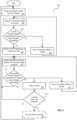
- FIG. 2 is a flowchart illustrating an example embodiment of a method.
- strict deterministic scheduling coordination is performed in two phases: (1) an initial coordination phase; and (2) a continuous monitoring phase.
- the initial coordination phase is used to coordinate the periodic scheduling of the emitter with the periodic scheduling of the switch. In some such example embodiments, the initial coordination phase is performed at the time the link between the emitter and the switch is established. At the conclusion of the initial coordination phase, the operational service (i . e ., a strict deterministic network link) between the emitter and the switch is opened/activated for transmitting operational data.
- the operational service i . e ., a strict deterministic network link
- the second phase sometimes referred to as the continuous monitoring phase
- the relative drift between a clock of the emitter and a clock of the switch is monitored and operational transmissions by the emitter are adjusted accordingly. It will be appreciated that in at least some example embodiments, no clock synchronization between the emitter and the receiver is performed. In at least one embodiment, monitoring is continuously performed while the service/link is open.
- an emitter and a receiver obtain a common schedule, sometimes referred to herein as a shared communication schedule.
- the common schedule may specify scheduled receive times for the receiver, and scheduled transmit times for the emitter.
- the common schedule may specify one or more windows during which communications between the emitter and receiver are to be conducted via a deterministic-compliant link, and the emitter is constrained to transmit only during one of the specified windows.
- the common schedule may specify that the one or more windows open periodically in some example embodiments.
- the common schedule may, in some example embodiments, specify a window start and duration, a time between windows, specific window open and close times, and/or other information that instructs the emitter when transmissions are permitted, and notifies the receiver when transmissions from the emitter are expected to arrive.
- a receiver determines a transmission offset based on differences between expected transmission arrival times and actual transmission arrival times.
- an expected arrival time of packets at the receiver may take into account an estimated latency associated with the deterministic-compliant communication link.
- the expected arrival time may assume an ideal transmission line. In either case, strict deterministic scheduling coordination can be used to adjust for any variance between actual arrival times expected arrival times.
- an initial coordination phase may begin with the emitter transmitting a defined and/or predefined frame, sometimes referred to as a probe, at or near the beginning of a scheduled opening of a communication window on the deterministic-compliant link.
- the schedule may specify periodic transmission and receipt of probes during the initial coordination phase.
- an expected receive time of the probe at the receiver is based on a scheduled transmission by the emitter. Any difference between the date at which the transmission is actually received, and the date at which the transmission is scheduled to be received, sometimes referred to herein as a variance, may be used by the receiver to determine a transmission offset to be applied at the emitter.
- the receiver checks to see if the current variance between expected/actual receipt of data is acceptable.
- current variance refers to a most recent variance between the receiver's expected and actual receipt of a transmission from the emitter via the deterministic-compliant link connecting the receiver and the emitter.
- acceptable variance refers to a difference of less than one clock cycle, or a time equivalent to less than one clock cycle, between the expected and actual receipt of the probe or other transmission from the emitter.
- the receiver in response to receipt of each probe or other transmission, determines a current variance, determines a transmission offset based on that variance, and sends a control message/signal to inform the emitter that the probe or other transmission arrived too early or too late relative to the date indicated by the common schedule.
- the transmission offset may be the same or substantially the same as the variance.
- blocks 203, 205, and 207 are repeated until block 205 indicates that the arrival of the frames complies with the common schedule (the variance is acceptable).
- the deterministic-compliant communication link is opened/activated for use in transmitting operational data, and the initial coordination phase may be considered complete.
- a variance of less than one clock cycle is considered acceptable.
- Various example embodiments, however, are not limited to using one clock cycle as the threshold for determining when a communication link is to be activated/opened.
- opening/activating a communication link for use in transmitting operational data includes stopping initial coordination between a receiver and an emitter to establish an initial transmission offset, and beginning to transmit operational data using that initial offset.
- the link may be opened/activated in response to a message transmitted from the receiver to the emitter. For example, in response to the receiver determining a current variance between the expected arrival time of frames transmitted by the emitter and an actual arrival time of those frames is acceptable, the receiver may transmit a message to the emitter indicating that the variance is acceptable. In response to receiving that message, the emitter may know that it can begin transmitting operational data to receiver. In other embodiments, the receiver may send a message to the emitter explicitly indicating that the link is open/activated.
- the term "operational data" refers to data including content that is not purely for purposes of establishing a transmission offset. In at least one example embodiment, prior to opening/activating the link, the emitter does not send operational data over the link.
- the receiver determines whether an operational variance between expected/actual receipt of data at the receiver is acceptable. If the operational variance is determined to be unacceptable, for example because the operational variance exceeds a threshold value, method 200 may proceed in parallel as indicated by blocks 215 and 217.
- the receiver may send a notification to a controller indicating the operational variance between expected and actual arrival of operational data at the receiver, the transmission offset determined by the receiver, and/or other information relevant to schedule generation by the controller.
- the receiver transmits a control message to the emitter indicating the transmission offset to be used by the emitter, and the emitter applies the transmission offset to transmission of operational data frames, packets, and/or the like.
- monitoring and adjustment of transmissions is performed continually during a time the deterministic-compliant link is open/active.
- the controller may optionally deactivate the link for use in transmitting operational data, and return to block 201 at which the controller transmits a new/updated shared schedule to the emitter and receiver.
- the controller may allow the receiver and the emitter to continue to attempt coordination until the current communication window is closed, and transmit a new/updated shared schedule to the emitter and receiver, as illustrated by block 201, for use during subsequent communication windows.
- the controller may periodically send a new/updated common schedule.
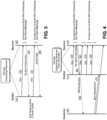
- example embodiments of signal flow during an initial coordination phase of strict deterministic scheduling coordination will be discussed.
- the following discussion assumes that emitter 310 and the receiver 320 share a common (e.g., predefined) periodic schedule.
- emitter 310 sends data 330 in the form of defined or predefined frames (i.e ., probes) according to the common schedule.
- the receiver 320 compares the arrival of these frames with the common schedule, and sends a control message 340 to inform the emitter 310 that these frames arrived too early or too late relative to the expected arrival date indicated by the common schedule.
- the probe arrived three clock cycles too early.
- the emitter shifts its periodic scheduling according to the control message received from receiver 320, which in this example means that the emitter 310 will send the next probe 331 three clock cycles later than the first transmission. Sending the probe, comparing the arrival date to the scheduled arrival date, transmitting the control message, adjusting sending date of probes are repeated while the arrival of the probes do not comply with the common schedule.
- the receiver 320 In response to the receiver 320 determining that arrival of the probes complies with the common schedule, the receiver 320 signals the emitter in a second control message 360 that a strict deterministic service is now open/active for transmission of operational data, and that the initial coordination phase has been completed.
- the second control message 360 may be a different type of message that explicitly indicates that the service is open, while in other example embodiments a control message used to open the service may simply indicate that the probe arrived at the expected time, e.g., zero clock cycles difference.
- receiver 320 may also notify a central controller (not illustrated) that the service is open, e.g., a deterministic-compliant link is active. In further example embodiments, the receiver may also send the controller information regarding shifts in the sending date.
- emitter 410 and the receiver 420 share a common (e.g., predefined) periodic schedule, which in at least one example embodiment is provided by controller 405.
- emitter 410 sends operational data 430, for example operational frames, according to the common schedule.
- Receiver 420 compares the arrival of one or more of these frames with the common schedule, and sends a control message 440 to inform the emitter that the frames arrived too early or too late relative to the common schedule.
- Receiver 420 also informs central controller 405 in message 445.
- the operational data is received N clock cycles late.
- the emitter 410 shifts its periodic scheduling according to the control message 440, i.e., by N clock cycles, and transmits future data 431, 432, and 433 using the shifted schedule. Sending the operational data, comparing the arrival date to the scheduled arrival date, transmitting the control message, and shifting the sending date of probe as necessary are repeated while the arrival of the operational data does not match scheduled arrival times indicated by the common schedule.
- the central controller 405 determines, based on message 445 transmitted by receiver 420, whether the common schedule provided to emitter 410 and receiver 420 in the strict deterministic network needs to be reorganized because of any relative drift of clocks associated with emitter 410 and receiver 420. Central controller 405 may then send a new common schedule 470 to both emitter 410 and receiver 420.
- an emitter line card sends a 32 bit word at the beginning of the period designated by the common schedule for periodic scheduling.
- a switch line card (not illustrated) counts the number N of clock cycles (3.85 ns each) since the beginning of the period designated for periodic scheduling.
- a transceiver included in the line card changes the status of the line from control (idle) to operational data, and the switch line card checks the number N of clock cycles. If this number N is null, then emitter and switch are coordinated. If this number N is not null, then the switch sends to the emitter a 32 bit word encoding the number N. In response to receiving the 32 bit word, the emitter offsets its own periodic scheduling of the number N. In at least one example embodiment, the emitter and switch are now coordinated.
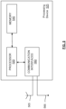
- processing device 525 configurable to implement example embodiments of an emitter, a receiver, a controller, a switch and/or other devices and equipment disclosed herein.
- processing device 525 includes: a memory 540; a processor 520 connected to the memory 540; various interfaces 560 connected to the processor 520; one or more (e.g., a plurality of) antennas or antenna panels 565 connected to the various interfaces 560; and one or more wired connections 566.
- the various interfaces 560 and the antenna 565 may constitute a transceiver for transmitting/receiving data from/to other network elements via one or more antenna beams.
- interfaces 560 may include native optical switching interfaces, 1 Tbps per port packet switches, and/or the like. Some such interfaces may be used by processing device 525 to communicate via large native IP networks without requiring optical-electrical-optical (OEO) conversion. Depending on the implementation of processing device 525, the processing device 525 may include many more components than those shown in FIG. 5 . However, it is not necessary that generally conventional components be shown in order to disclose the illustrative example embodiment(s).
- the memory 540 may be a computer readable storage medium that generally includes a random-access memory (RAM), read only memory (ROM), and/or a permanent mass storage device, such as a disk drive.
- the memory 540 also stores an operating system and any other routines/modules/applications for providing the functionalities of processing device 525 to be executed by the processor 520.
- These software components may also be loaded from a separate computer readable storage medium into the memory 540 using a drive mechanism (not shown).
- Such separate computer readable storage medium may include a disc, tape, DVD/CD-ROM drive, memory card, or other like computer readable storage medium (not shown).
- software components may be loaded into the memory 540 via one of the various interfaces 560, rather than via a computer readable storage medium.
- the processor 520 may be configured to carry out instructions of a computer program by performing the arithmetical, logical, and input/output operations of the system. Instructions may be provided to the processor 520 by the memory 540.
- the various interfaces 560 may include components that interface the processor 520 with the antenna 565, or other input/output components. As will be understood, the various interfaces 560 and programs stored in the memory 540 to set forth the special purpose functionalities of the SDN controller will vary depending on the implementation of the processing device 525.
- the interfaces 560 may also include one or more user input devices (e.g., a keyboard, a keypad, a mouse, or the like) and user output devices (e.g., a display, a speaker, or the like).
- user input devices e.g., a keyboard, a keypad, a mouse, or the like
- user output devices e.g., a display, a speaker, or the like.
- At least one memory may include or store computer-executable instructions which, when executed by at least one processor, cause and SDN controller or a trust manager to perform one or more operations discussed herein.
- Such existing hardware may be processing or control circuitry such as, but not limited to, one or more processors, one or more Central Processing Units (CPUs), one or more controllers, one or more arithmetic logic units (ALUs), one or more digital signal processors (DSPs), one or more microcomputers, one or more field programmable gate arrays (FPGAs), one or more System-on-Chips (SoCs), one or more programmable logic units (PLUs), one or more microprocessors, one or more Application Specific Integrated Circuits (ASICs), or any other device or devices capable of responding to and executing instructions in a defined manner.
- processors Central Processing Units (CPUs), one or more controllers, one or more arithmetic logic units (ALUs), one or more digital signal processors (DSPs), one or more microcomputers, one or more field programmable gate arrays (FPGAs), one or more System-on-Chips (SoCs), one or more programmable logic units (PLUs
- a process may be terminated when its operations are completed, but may also have additional steps not included in the figure.
- a process may correspond to a method, function, procedure, subroutine, subprogram, etc.
- a process corresponds to a function
- its termination may correspond to a return of the function to the calling function or the main function.
- the term “storage medium,” “computer readable storage medium” or “non-transitory computer readable storage medium” may represent one or more devices for storing data, including read only memory (ROM), random access memory (RAM), magnetic RAM, core memory, magnetic disk storage mediums, optical storage mediums, flash memory devices and/or other tangible machine-readable mediums for storing information.
- ROM read only memory
- RAM random access memory
- magnetic RAM magnetic RAM
- core memory magnetic disk storage mediums
- optical storage mediums optical storage mediums
- flash memory devices and/or other tangible machine-readable mediums for storing information.
- computer-readable medium may include, but is not limited to, portable or fixed storage devices, optical storage devices, and various other non-transitory, physical media capable of storing or instruction(s) and/or data.
- example embodiments may be implemented by hardware, software, firmware, middleware, microcode, hardware description languages, or any combination thereof.
- the program code or code segments to perform the necessary tasks may be stored in a machine or computer readable medium such as a computer readable storage medium.
- a processor or processors will perform the necessary tasks.
- at least one memory may include or store computer program code
- the at least one memory and the computer program code may be configured to, with at least one processor, cause a network element or network device to perform the necessary tasks.
- the processor, memory, and example algorithms, encoded as computer program code serve as means for providing or causing performance of operations discussed herein.
- a code segment of computer program code may represent a procedure, function, subprogram, program, routine, subroutine, module, software package, class, or any combination of instructions, data structures or program statements.
- a code segment may be coupled to another code segment or a hardware circuit by passing and/or receiving information, data, arguments, parameters, or memory contents.
- Information, arguments, parameters, data, etc. may be passed, forwarded, or transmitted via any suitable technique including memory sharing, message passing, token passing, network transmission, etc.
- Some, but not all, examples of techniques available for communicating or referencing the object/information being indicated include the conveyance of the object/information being indicated, the conveyance of an identifier of the object/information being indicated, the conveyance of information used to generate the object/information being indicated, the conveyance of some part or portion of the object/information being indicated, the conveyance of some derivation of the object/information being indicated, and the conveyance of some symbol representing the object/information being indicated.
- user equipment may be (or include) hardware, firmware, hardware executing software or any combination thereof.
- Such hardware may include processing or control circuitry such as, but not limited to, one or more processors, one or more CPUs, one or more controllers, one or more ALUs, one or more DSPs, one or more microcomputers, one or more FPGAs, one or more SoCs, one or more PLUs, one or more microprocessors, one or more ASICs, or any other device or devices capable of responding to and executing instructions in a defined manner.
Landscapes
- Engineering & Computer Science (AREA)
- Computer Networks & Wireless Communication (AREA)
- Signal Processing (AREA)
- Physics & Mathematics (AREA)
- Optics & Photonics (AREA)
- Optical Communication System (AREA)
Applications Claiming Priority (1)
| Application Number | Priority Date | Filing Date | Title |
|---|---|---|---|
| US18/398,654 US20250219806A1 (en) | 2023-12-28 | 2023-12-28 | Strict deterministic scheduling coordination |
Publications (1)
| Publication Number | Publication Date |
|---|---|
| EP4580159A1 true EP4580159A1 (de) | 2025-07-02 |
Family
ID=93925450
Family Applications (1)
| Application Number | Title | Priority Date | Filing Date |
|---|---|---|---|
| EP24221491.4A Pending EP4580159A1 (de) | 2023-12-28 | 2024-12-19 | Streng deterministische planungskoordination |
Country Status (2)
| Country | Link |
|---|---|
| US (1) | US20250219806A1 (de) |
| EP (1) | EP4580159A1 (de) |
Citations (3)
| Publication number | Priority date | Publication date | Assignee | Title |
|---|---|---|---|---|
| CN101534222A (zh) * | 2008-03-10 | 2009-09-16 | 中国移动通信集团公司 | 端到端网络时延抖动测量方法、装置及系统 |
| US20130138800A1 (en) * | 2011-11-30 | 2013-05-30 | Harman International Industries, Incorporated | System for optimizing latency in an avb network |
| US20230327910A1 (en) * | 2020-11-30 | 2023-10-12 | Fort Robotics, Inc. | System and method for safety message latency characterization |
Family Cites Families (6)
| Publication number | Priority date | Publication date | Assignee | Title |
|---|---|---|---|---|
| JP3058132B2 (ja) * | 1997-09-05 | 2000-07-04 | 日本電気株式会社 | コンピュータ間時刻同期合わせ方法および方式 |
| US8340790B2 (en) * | 2009-08-31 | 2012-12-25 | Fisher-Rosemount Systems, Inc. | Methods and apparatus to adjust control loop timing in a process control system |
| US10439940B2 (en) * | 2017-10-19 | 2019-10-08 | Cisco Technology, Inc. | Latency correction between transport layer host and deterministic interface circuit |
| CN110868363B (zh) * | 2018-08-27 | 2021-11-19 | 华为技术有限公司 | 周期映射的方法及网络设备 |
| WO2020155149A1 (en) * | 2019-02-02 | 2020-08-06 | Lenovo (Beijing) Limited | Enhanced scheduling of time sensitive networking |
| US12058601B2 (en) * | 2021-02-25 | 2024-08-06 | Nokia Solutions And Networks Oy | Electronic packet switching based on traffic properties |
-
2023
- 2023-12-28 US US18/398,654 patent/US20250219806A1/en active Pending
-
2024
- 2024-12-19 EP EP24221491.4A patent/EP4580159A1/de active Pending
Patent Citations (3)
| Publication number | Priority date | Publication date | Assignee | Title |
|---|---|---|---|---|
| CN101534222A (zh) * | 2008-03-10 | 2009-09-16 | 中国移动通信集团公司 | 端到端网络时延抖动测量方法、装置及系统 |
| US20130138800A1 (en) * | 2011-11-30 | 2013-05-30 | Harman International Industries, Incorporated | System for optimizing latency in an avb network |
| US20230327910A1 (en) * | 2020-11-30 | 2023-10-12 | Fort Robotics, Inc. | System and method for safety message latency characterization |
Also Published As
| Publication number | Publication date |
|---|---|
| US20250219806A1 (en) | 2025-07-03 |
Similar Documents
| Publication | Publication Date | Title |
|---|---|---|
| US10404608B2 (en) | Systems, devices, and methods for low-jitter communication over a packet-switched network | |
| US20240214323A1 (en) | Packet transmission method and apparatus | |
| US11088962B2 (en) | Method for performant data transmission in a data network with, in part, real-time requirements and apparatus for carrying out the method | |
| WO2021059683A1 (en) | Method for transmitting data packets and apparatus for implementing the same | |
| EP3734919A1 (de) | Bandinterne signalisierung zur dynamischen übertragungszeitfenstersteuerung | |
| CN114449586B (zh) | 一种通信调度方法、装置和存储介质 | |
| EP3278518B1 (de) | Netzwerkknoten | |
| Suethanuwong | Scheduling time-triggered traffic in TTEthernet systems | |
| CN112769514A (zh) | 基于时间敏感的通信设备 | |
| Kopetz et al. | Real-time communication | |
| CN117917065A (zh) | 用于为时间敏感性网络配置网络切片的系统和方法 | |
| JP6353932B2 (ja) | 光パケット送出方法及びデバイス、光パケット処理方法、並びに光スイッチングデバイス | |
| EP3166255B1 (de) | Schalten von terminierten rahmen in einem ethernet-basierten netzwerk in einem fahrzeug | |
| WO2024055897A1 (zh) | 报文处理方法、传递方法、通信设备、系统、介质及产品 | |
| Luo et al. | FCSQF: Flexible traffic control for ECT-aware time sensitive networking | |
| EP3166257B1 (de) | Startauslösung in einem ethernet-basierten fahrzeugnetzwerk | |
| EP4580159A1 (de) | Streng deterministische planungskoordination | |
| CN112688812B (zh) | 应用于电力数据传输的可靠性感知时间敏感网络路由方法 | |
| US20200403939A1 (en) | A664 synch network design | |
| CN109525315A (zh) | 基于时间触发的光纤通道网络端系统 | |
| EP2273706B1 (de) | Synchronisationspaketverzögerungsveränderungsabschwächung | |
| WO2024055898A1 (zh) | 报文处理方法、传递方法、通信设备、系统、介质及产品 | |
| Cuong et al. | Supporting hard real-time communication of periodic messages over switched ethernet | |
| CN110098967B (zh) | 一种通信方法、装置、设备及介质 | |
| CN117319163A (zh) | 业务数据的传输方法、设备、电子设备和存储介质 |
Legal Events
| Date | Code | Title | Description |
|---|---|---|---|
| PUAI | Public reference made under article 153(3) epc to a published international application that has entered the european phase |
Free format text: ORIGINAL CODE: 0009012 |
|
| STAA | Information on the status of an ep patent application or granted ep patent |
Free format text: STATUS: THE APPLICATION HAS BEEN PUBLISHED |
|
| AK | Designated contracting states |
Kind code of ref document: A1 Designated state(s): AL AT BE BG CH CY CZ DE DK EE ES FI FR GB GR HR HU IE IS IT LI LT LU LV MC ME MK MT NL NO PL PT RO RS SE SI SK SM TR |
|
| STAA | Information on the status of an ep patent application or granted ep patent |
Free format text: STATUS: REQUEST FOR EXAMINATION WAS MADE |
|
| 17P | Request for examination filed |
Effective date: 20251211 |