EP4580170A1 - Dispositif électronique comprenant une unité d'affichage coulissante et son procédé de fonctionnement - Google Patents
Dispositif électronique comprenant une unité d'affichage coulissante et son procédé de fonctionnement Download PDFInfo
- Publication number
- EP4580170A1 EP4580170A1 EP23860945.7A EP23860945A EP4580170A1 EP 4580170 A1 EP4580170 A1 EP 4580170A1 EP 23860945 A EP23860945 A EP 23860945A EP 4580170 A1 EP4580170 A1 EP 4580170A1
- Authority
- EP
- European Patent Office
- Prior art keywords
- display
- electronic device
- slidable
- slidable display
- area
- Prior art date
- Legal status (The legal status is an assumption and is not a legal conclusion. Google has not performed a legal analysis and makes no representation as to the accuracy of the status listed.)
- Pending
Links
Images









Classifications
-
- G—PHYSICS
- G06—COMPUTING OR CALCULATING; COUNTING
- G06F—ELECTRIC DIGITAL DATA PROCESSING
- G06F1/00—Details not covered by groups G06F3/00 - G06F13/00 and G06F21/00
- G06F1/16—Constructional details or arrangements
- G06F1/1613—Constructional details or arrangements for portable computers
- G06F1/1615—Constructional details or arrangements for portable computers with several enclosures having relative motions, each enclosure supporting at least one I/O or computing function
- G06F1/1624—Constructional details or arrangements for portable computers with several enclosures having relative motions, each enclosure supporting at least one I/O or computing function with sliding enclosures, e.g. sliding keyboard or display
-
- G—PHYSICS
- G06—COMPUTING OR CALCULATING; COUNTING
- G06F—ELECTRIC DIGITAL DATA PROCESSING
- G06F1/00—Details not covered by groups G06F3/00 - G06F13/00 and G06F21/00
- G06F1/16—Constructional details or arrangements
- G06F1/1613—Constructional details or arrangements for portable computers
- G06F1/1633—Constructional details or arrangements of portable computers not specific to the type of enclosures covered by groups G06F1/1615 - G06F1/1626
- G06F1/1637—Details related to the display arrangement, including those related to the mounting of the display in the housing
- G06F1/1652—Details related to the display arrangement, including those related to the mounting of the display in the housing the display being flexible, e.g. mimicking a sheet of paper, or rollable
-
- G—PHYSICS
- G06—COMPUTING OR CALCULATING; COUNTING
- G06F—ELECTRIC DIGITAL DATA PROCESSING
- G06F3/00—Input arrangements for transferring data to be processed into a form capable of being handled by the computer; Output arrangements for transferring data from processing unit to output unit, e.g. interface arrangements
- G06F3/01—Input arrangements or combined input and output arrangements for interaction between user and computer
- G06F3/048—Interaction techniques based on graphical user interfaces [GUI]
- G06F3/0481—Interaction techniques based on graphical user interfaces [GUI] based on specific properties of the displayed interaction object or a metaphor-based environment, e.g. interaction with desktop elements like windows or icons, or assisted by a cursor's changing behaviour or appearance
-
- G—PHYSICS
- G09—EDUCATION; CRYPTOGRAPHY; DISPLAY; ADVERTISING; SEALS
- G09G—ARRANGEMENTS OR CIRCUITS FOR CONTROL OF INDICATING DEVICES USING STATIC MEANS TO PRESENT VARIABLE INFORMATION
- G09G3/00—Control arrangements or circuits, of interest only in connection with visual indicators other than cathode-ray tubes
- G09G3/03—Control arrangements or circuits, of interest only in connection with visual indicators other than cathode-ray tubes specially adapted for displays having non-planar surfaces, e.g. curved displays
- G09G3/035—Control arrangements or circuits, of interest only in connection with visual indicators other than cathode-ray tubes specially adapted for displays having non-planar surfaces, e.g. curved displays for flexible display surfaces
-
- H—ELECTRICITY
- H04—ELECTRIC COMMUNICATION TECHNIQUE
- H04M—TELEPHONIC COMMUNICATION
- H04M1/00—Substation equipment, e.g. for use by subscribers
- H04M1/02—Constructional features of telephone sets
-
- H—ELECTRICITY
- H04—ELECTRIC COMMUNICATION TECHNIQUE
- H04M—TELEPHONIC COMMUNICATION
- H04M1/00—Substation equipment, e.g. for use by subscribers
- H04M1/02—Constructional features of telephone sets
- H04M1/0202—Portable telephone sets, e.g. cordless phones, mobile phones or bar type handsets
- H04M1/0206—Portable telephones comprising a plurality of mechanically joined movable body parts, e.g. hinged housings
- H04M1/0208—Portable telephones comprising a plurality of mechanically joined movable body parts, e.g. hinged housings characterized by the relative motions of the body parts
- H04M1/0235—Slidable or telescopic telephones, i.e. with a relative translation movement of the body parts; Telephones using a combination of translation and other relative motions of the body parts
-
- H—ELECTRICITY
- H04—ELECTRIC COMMUNICATION TECHNIQUE
- H04M—TELEPHONIC COMMUNICATION
- H04M1/00—Substation equipment, e.g. for use by subscribers
- H04M1/72—Mobile telephones; Cordless telephones, i.e. devices for establishing wireless links to base stations without route selection
- H04M1/724—User interfaces specially adapted for cordless or mobile telephones
- H04M1/72448—User interfaces specially adapted for cordless or mobile telephones with means for adapting the functionality of the device according to specific conditions
- H04M1/72454—User interfaces specially adapted for cordless or mobile telephones with means for adapting the functionality of the device according to specific conditions according to context-related or environment-related conditions
-
- G—PHYSICS
- G09—EDUCATION; CRYPTOGRAPHY; DISPLAY; ADVERTISING; SEALS
- G09G—ARRANGEMENTS OR CIRCUITS FOR CONTROL OF INDICATING DEVICES USING STATIC MEANS TO PRESENT VARIABLE INFORMATION
- G09G2340/00—Aspects of display data processing
- G09G2340/04—Changes in size, position or resolution of an image
-
- G—PHYSICS
- G09—EDUCATION; CRYPTOGRAPHY; DISPLAY; ADVERTISING; SEALS
- G09G—ARRANGEMENTS OR CIRCUITS FOR CONTROL OF INDICATING DEVICES USING STATIC MEANS TO PRESENT VARIABLE INFORMATION
- G09G2380/00—Specific applications
- G09G2380/02—Flexible displays
-
- H—ELECTRICITY
- H04—ELECTRIC COMMUNICATION TECHNIQUE
- H04M—TELEPHONIC COMMUNICATION
- H04M1/00—Substation equipment, e.g. for use by subscribers
- H04M1/02—Constructional features of telephone sets
- H04M1/0202—Portable telephone sets, e.g. cordless phones, mobile phones or bar type handsets
- H04M1/0206—Portable telephones comprising a plurality of mechanically joined movable body parts, e.g. hinged housings
- H04M1/0208—Portable telephones comprising a plurality of mechanically joined movable body parts, e.g. hinged housings characterized by the relative motions of the body parts
- H04M1/0235—Slidable or telescopic telephones, i.e. with a relative translation movement of the body parts; Telephones using a combination of translation and other relative motions of the body parts
- H04M1/0237—Sliding mechanism with one degree of freedom
Definitions
- a display using organic light emitting diodes may secure the portability of the electronic device while providing a larger screen.
- a display using, or equipped with, organic light emitting diodes may implement a stable operation even if it is made quite thin, so that the display may be applied to an electronic device in a foldable, bendable or rollable form.
- an electronic device may comprise a slidable display and a processor.
- the processor may be configured to display a screen including content on the slidable display.
- the processor may be configured to identify an event for automatically extending or contracting the slidable display by a designated size. The designated size may be determined based on the event.
- the processor may be configured to display an object for indicating a progress degree of extending or contracting the slidable display on the slidable display based on the event. The size of the object may be determined based on the designated size.
- the processor may be configured to apply a visual effect indicating the progress degree to the object while extending or contracting the slidable display by the designated size.
- a method for operating an electronic device may comprise displaying a screen including content on a slidable display included in the electronic device.
- the method for operating the electronic device may comprise identifying an event for automatically extending or contracting the slidable display by a designated size. The designated size may be determined based on the event.
- the method for operating the electronic device may comprise displaying an object for indicating a progress degree of extending or contracting the slidable display on the slidable display based on the event. The size of the object may be determined based on the designated size.
- the method for operating the electronic device may comprise applying a visual effect indicating the progress degree to the object while extending or contracting the slidable display by the designated size.
- the state shown in FIG. 1 may be defined as a first structure 101 being closed with respect to a second structure 102, and the state shown in FIG. 2 may be defined as the first structure 101 being open with respect to the second structure 102.
- the "closed state” or “opened state” may be defined as a closed or opened state of the electronic device.
- the electronic device 100 may include a first structure 101 and a second structure 102 movably disposed in the first structure 101.
- the electronic device 100 may be interpreted as having a structure in which the first structure 101 is slidably disposed on the second structure 102.
- the first structure 101 may be disposed to perform reciprocating motion between the closed state and the opened state in the shown direction with respect to the second structure 102, for example, a direction indicated by an arrow 1.
- the first structure 101 may include a first plate 111a (e.g., a slide plate) and may include a first surface F1 (refer to FIG. 3 ) formed with at least a portion of the first plate 111a and a second surface F2 facing in a direction opposite to the first surface F1.
- the second structure 102 may include a second plate 121a (see FIG.
- the second sidewall 123b and the third sidewall 123c may be formed to be perpendicular to the first sidewall 123a.
- the second plate 121a, the first sidewall 123a, the second sidewall 123b, and the third sidewall 123c may be formed to have an opening (e.g., in the front face) to receive (or surround) at least a portion of the first structure 101.
- the first structure 101 may be coupled to the second structure 102 in a state in which it is at least partially surrounded, and the first structure 101 may be slide in a direction parallel to the first surface F1 or the second surface F2, for example, direction 1 indicated with the arrow.
- the second sidewall 123b or the third sidewall 123c may be omitted.
- the second plate 121a, the first sidewall 123a, the second sidewall 123b, and/or the third sidewall 123c may be formed as separate structures and may be combined or assembled.
- the rear plate 121b may be coupled to surround at least a portion of the second plate 121a.
- the rear plate 121b may be formed substantially integrally with the second plate 121a.
- the second plate 121a or the rear plate 121b may cover at least a portion of the flexible display 103.
- the flexible display 103 may be at least partially received inside the second structure 102, and the second plate 121a or the rear plate 121b may cover a portion (e.g., the second area A2) of the flexible display 103 received inside the second structure 102.
- the first structure 101 may be moved in an open state or closed state with respect to the second structure 102 in a first direction (e.g., direction 1) parallel with the second plate 121a (e.g., the rear case) and the second side wall 123b to be positioned a first distance away from the first side wall 123a in the closed state and be positioned a second distance away from the first side wall 123a in the open state, wherein the second distance is larger than the first distance.
- the first structure 101 when in the closed state, may be positioned to surround a portion of the first sidewall 123a.
- the electronic device 100 may include a display 103, a key input device 141, a connector hole 143, audio modules 145a, 145b, 147a, and 147b, or a camera module 149.
- the electronic device 100 may further include an indicator (e.g., a light emitting diode (LED) device) or various sensor modules.
- LED light emitting diode
- the display 103 may include a first area A1 and a second area A2.
- the first area A1 may extend substantially across at least a portion of the first surface F1 and may be disposed on the first surface F1.
- the second area A2 may extend from the first area A1 and be inserted or received into, or exposed to the outside of, the second structure 102 (e.g., the housing) according to the slide of the first structure 101.
- the second area A2 may be moved while being substantially guided by a roller 151 (refer to FIG. 3 ) mounted on the second structure 102 and may thus be received into the inside of or exposed to the outside of the second structure 102.
- a portion of the second area A2 may be deformed into a curved shape in a position corresponding to the roller 151.
- the second area A2 when viewed from the top of the first plate 111a (e.g., slide plate), when the first structure 101 moves from the closed state to the opened state, the second area A2 may be gradually exposed to the outside of the second structure 102 to be substantially coplanar with the first area A1.
- the display 103 may be disposed to be coupled with, or adjacent, a touch detecting circuit, a pressure sensor capable of measuring the strength (pressure) of touches, and/or a digitizer for detecting a magnetic field-type stylus pen.
- the second area A2 may be at least partially received inside the second structure 102, and a portion of the second area A2 may be exposed to the outside even in the state shown in FIG. 1 (e.g., the closed state).
- the exposed portion of the second area A2 may be positioned on the roller 151 and, in a position corresponding to the roller 151, a portion of the second area A2 may maintain the curved shape.
- the key input device 141 may be disposed on the second sidewall 123b or the third sidewall 123c of the second structure 102. Considering the appearance and the state of use, the electronic device 100 may be manufactured to omit the illustrated key input device 141 or to include additional key input device(s). According to an embodiment, the electronic device 100 may include a key input device (not shown), e.g., a home key button or a touchpad disposed around the home key button. According to another embodiment, at least a portion of the key input device 141 may be positioned on an area of the first structure 101.
- the connector hole 143 may be omitted or may receive a connector (e.g., a universal serial bus (USB) connector) for transmitting and receiving power and/or data with an external electronic device.
- a connector e.g., a universal serial bus (USB) connector
- the electronic device 100 may include a plurality of connector holes 143, and some of the plurality of connector holes 143 may function as connector holes for transmitting/receiving audio signals with an external electronic device.
- the connector hole 143 is disposed in the third sidewall 123c, but the present invention is not limited thereto.
- the connector hole 143 or an additional connector hole not shown may be disposed in the first sidewall 123a or the second sidewall 123b.
- the audio modules 145a, 145b, 147a, and 147b may include speaker holes 145a and 145b or microphone holes 147a and 147b.
- One of the speaker holes 145a and 145b may be provided as a receiver hole for voice calls, and the other may be provided as an external speaker hole.
- the microphone holes 147a and 147b may have a microphone inside to obtain external sounds. According to an embodiment, there may be a plurality of microphones to be able to detect the direction of a sound.
- the speaker holes 145a and 145b and the microphone holes 147a and 147b may be implemented as one hole, or a speaker may be included without the speaker holes 145a and 145b (e.g., a piezo speaker).
- the speaker hole indicated by the reference number "145b” may be disposed in the first structure 101 and used as a receiver hole for voice calls, and the speaker hole indicated by the reference number "145a” (e.g., an external speaker hole) or the microphone holes 147a and 147b may be disposed in the second structure 102 (e.g., one of the side surfaces 123a, 123b, and 123c).
- the camera module 149 may be provided on the second structure 102 and may capture a subject in a direction opposite to the first area A1 of the display 103.
- the electronic device 100 may include a plurality of camera modules 149.
- the electronic device 100 may include a wide-angle camera, a telephoto camera, or a close-up camera, and according to an embodiment, by including an infrared projector and/or an infrared receiver, the electronic device 600 may measure the distance to the subject.
- the camera module 149 may include one or more lenses, an image sensor, and/or an image signal processor.
- the electronic device 100 may further include a camera module (e.g., a front camera) that captures the subject in the same direction as the first area A1 of the display 103.
- the front camera may be disposed around the first area A1 or in an area overlapping the display 103 and, when disposed in the area overlapping the display 103, the front camera may capture the subject via the display 103.
- an indicator (not shown) of the electronic device 100 may be disposed on the first structure 101 or the second structure 102, and the indicator may include a light emitting diode to provide state information about the electronic device 100 as a visual signal.
- the sensor module (not shown) of the electronic device 100 may produce an electrical signal or data value corresponding to the internal operation state or external environment state of the electronic device.
- the sensor module may include, for example, a proximity sensor, a fingerprint sensor, or a biometric sensor (e.g., an iris/face recognition sensor or a heartrate monitor (HRM) sensor).
- HRM heartrate monitor
- the sensor module may further include, e.g., at least one of a gesture sensor, a gyro sensor, an atmospheric pressure sensor, a magnetic sensor, an acceleration sensor, a grip sensor, a color sensor, an infrared (IR) sensor, a temperature sensor, a humidity sensor, or an illuminance sensor.
- a gesture sensor e.g., a gesture sensor, a gyro sensor, an atmospheric pressure sensor, a magnetic sensor, an acceleration sensor, a grip sensor, a color sensor, an infrared (IR) sensor, a temperature sensor, a humidity sensor, or an illuminance sensor.
- a gyro sensor e.g., an atmospheric pressure sensor, a magnetic sensor, an acceleration sensor, a grip sensor, a color sensor, an infrared (IR) sensor, a temperature sensor, a humidity sensor, or an illuminance sensor.
- IR infrared
- FIG. 3 is an exploded perspective view illustrating an electronic device (e.g., the electronic device 100 of FIG. 1 or 2 ) according to various embodiments of the disclosure.
- FIG. 4A is a bottom view illustrating a state in which a flexible display 103 of an electronic device (e.g., the electronic device 100 of FIGS. 1 to 3 ) is mounted according to various embodiments of the disclosure.
- the electronic device 100 may include a first structure 101, a second structure 102 (e.g., a housing), a display 103 (e.g., a flexible display), a guide member (e.g., the roller 151), an articulated hinge structure 113, and/or at least one antenna structure 161.
- a portion (e.g., the second area A2) of the display 103 may be received in the second structure 102 while being guided by the roller 151.
- the first structure 101 may include a first plate 111a (e.g., a slide plate), a first bracket 111b and/or a second bracket 111c mounted on the first plate 111a.
- the first structure 101 for example, the first plate 111a, the first bracket 111b, and/or the second bracket 111c may be formed of a metallic material and/or a non-metallic (e.g., polymer) material.
- the first plate 111a may be mounted on the second structure 102 (e.g., the housing) and may be linearly reciprocated in one direction (e.g., in the direction 1 indicated with the arrow in FIG. 1 ) while being guided by the second structure 102.
- the articulated hinge structure 113 may be substantially received into the inside of the second structure 102 and, in the opened state (e.g., the state illustrated in FIG. 2 ), the articulated hinge structure may be extracted to the outside of the second structure 102.
- the opened state e.g., the state illustrated in FIG. 2
- the articulated hinge structure may be extracted to the outside of the second structure 102.
- a portion of the articulated hinge structure 113 may not be received inside the second structure 102.
- a portion of the articulated hinge structure 113 may be positioned to correspond to the roller 151 outside the second structure 102.
- the rods of the articulated hinge structure 113 may orbit around other adjacent rods while remaining parallel to the other adjacent rods.
- a portion of the articulated hinge structure 113, which faces the roller 151 may form a curved surface
- another portion of the articulated hinge structure 213, which does not face the roller 151 may form a flat surface.
- the second area A2 of the display 103 may be mounted or supported on the articulated hinge structure 113 and, in the open state (e.g., the state shown in FIG. 2 ), the second area A2, along with the first area A1, may be exposed to the outside of the second structure 102.
- the articulated hinge structure 113 may substantially form a flat surface, thereby supporting or maintaining the second area A2 in the flat state.
- the second structure 102 may include a second plate 121a (e.g., the rear case), a printed circuit board (not shown), a rear plate 121b, a third plate 121c (e.g., the front case), and a supporting member 121d.
- the second plate 121a e.g., the rear case, may be disposed to face in a direction opposite to the first surface F1 of the first plate 111a, and the second plate 121a may substantially form the external shape of the second structure 102 or the electronic device 100.
- the second structure 102 may include a first sidewall 123a extending from the second plate 121a, a second sidewall 123b extending from the second plate 121a and formed to be substantially perpendicular to the first sidewall 123a, and a third sidewall 123c extending from the second plate 121a, substantially perpendicular to the first sidewall 123a, and parallel to the second sidewall 123b.
- the second sidewall 123b and the third sidewall 123c are manufactured as separate components from the second plate 121a and are mounted or assembled on the second plate 121a.
- the second sidewall 123b and the third sidewall 123c may alternatively be integrally formed with the second plate 121a.
- the rear plate 121b may be coupled to the outer surface of the second plate 121a and, according to an embodiment, the rear plate 121b may be manufactured integrally with the second plate 121a.
- the second plate 121a may be formed of a metal or polymer, and the rear plate 121b may be formed of a material such as metal, glass, synthetic resin, or ceramic to decorate the exterior of the electronic device 100.
- the second plate 121a and/or the rear plate 121b may be formed of a material that transmits light at least partially (e.g., the auxiliary display area A3).
- the display 103 in a state in which a portion (e.g., the second area A2) of the display 103 is received into the inside of the second structure 102, at least a portion of the second area A2 may be positioned corresponding to the auxiliary display area A3.
- the display 103 in a state of being received inside the second structure 102, the display 103 may output a screen using at least a portion of the second area A2, and the user may recognize the screen output through the auxiliary display area A3.
- the third plate 121c may be formed of a metal or polymer, and the third plate 121c may be coupled with the second plate 121a (e.g., rear case), the first sidewall 123a, the second sidewall 123b, and/or the third sidewall 123c to form an internal space of the second structure 102.
- the third plate 121c may be referred to as a "front case", and the first structure 101, e.g., the first plate 111a, may be slid while substantially facing the third plate 121c.
- the first sidewall 123a may be formed of a combination of a first sidewall portion 123a-1 extending from the second plate 121a and a second sidewall portion 123a-2 formed at an edge of the third plate 121c.
- the first sidewall portion 123a-1 may be coupled to surround an edge of the third plate 121c, e.g., the second sidewall portion 123a-2. In this case, the first sidewall portion 123a-1 itself may form the first sidewall 123a.
- the support member 121d may be disposed in a space between the second plate 121a and the third plate 121c, and may have a flat plate shape formed of a metal or polymer.
- the support member 121d may provide an electromagnetic shielding structure in the internal space of the second structure 102 or may increase mechanical rigidity of the second structure 102.
- a partial area e.g., the second area A2
- the articulated hinge structure 113 and/or the display 103 may be positioned in a space between the second plate 121a and the support member 121d.
- a printed circuit board (not shown) may be disposed in a space between the third plate 121c and the support member 121d.
- the printed circuit board may be accommodated in a space separated by the support member 121d from the space in which a partial area of the multi-joint hinge structure 113 and/or the display 103 is accommodated inside the second structure 102.
- a processor, memory, and/or interface may be mounted on the printed circuit board.
- the processor may include one or more of, e.g., a central processing unit, an application processor, a graphic processing device, an image signal processing, a sensor hub processor, or a communication processor.
- the memory may include, e.g., a volatile or non-volatile memory.
- the interface may include, e.g., a high definition multimedia interface (HDMI), a universal serial bus (USB) interface, a secure digital (SD) card interface, and/or an audio interface.
- HDMI high definition multimedia interface
- USB universal serial bus
- SD secure digital
- the interface may electrically or physically connect, e.g., the electronic device 100 with an external electronic device and may include a USB connector, an SD card/multimedia card (MMC) connector, or an audio connector.
- MMC multimedia card
- the display 103 may be an organic light emitting diode-based flexible display, and the display 103 may normally remain in the flat shape and may be at least partially deformed into a curved shape.
- the first area A1 of the display 103 may be mounted or attached to the first surface F1 of the first structure 101 and maintained in a substantially flat shape.
- the second area A2 may extend from the first area A1 and may be supported or attached to the multi-joint hinge structure 113.
- the second area A2 may extend along the sliding direction of the first structure 101 and, along with the multi-joint hinge structure, may be accommodated in the second structure 102. As the multi-joint hinge structure 113 is deformed, the second area A2 may be at least partially deformed into a curved shape.
- the area of the display 103 exposed to the outside may vary.
- the electronic device 100 e.g., processor
- the electronic device 100 may deactivate the entire area of the display 103.
- the electronic device 100 may activate a partial area of the display 103 to provide visual information, as necessary (e.g., a notification according to the user setting, a missed call/message arrival notification), through the auxiliary display area A3.
- the entire area (e.g., the first area A1 and the second area A2) of the display 103 may be substantially exposed to the outside, and the first area A1 and the second area A2 may be arranged to form a plane.
- a portion (e.g., one end) of the second area A2 may be positioned corresponding to the roller 151, and the portion of the second area A2, which corresponds to the roller 151 may remain in the curved shape.
- the second area A2 is disposed to form a plane in the opened state
- a portion of the second area A2 may remain in the curved shape.
- the articulated hinge structure 113 and/or the second area A2 are received inside the second structure 102
- a portion of the second area A2 of the articulated hinge structure 113 may be positioned outside the second structure 102.
- the guide member e.g., the roller 151
- the roller 151 may be rotatably mounted on the second structure 102 in a position adjacent to an edge of the second structure 102 (e.g., the second plate 121a).
- the roller 151 may be disposed adjacent to an edge (e.g., the portion indicated with reference denotation 'IE') of the second plate 121a parallel to the first side wall 123a.
- another sidewall may extend from the edge of the second plate 121a, and the sidewall adjacent to the roller 151 may be substantially parallel to the first sidewall 123a.
- the sidewall of the second structure 102 adjacent to the roller 151 may be formed of a material that transmits light, and a portion of the second area A2 may provide visual information via the portion of the second structure 102 while being received in the second structure 102.
- an end of the roller 151 may be rotatably coupled to the second sidewall 123b, and the other end thereof may be rotatably coupled to the third sidewall 123c.
- the roller 151 may be mounted on the second structure 102, rotating about the rotation axis R perpendicular to the sliding direction (e.g., direction 1 indicated with the arrow in FIG. 1 or 2 ) of the first structure 101.
- the rotation axis R may be disposed substantially parallel to the first side wall 123a, and may be positioned away from the first side wall 123a, for example, at one edge of the second plate 121a.
- the gap formed between the outer circumferential surface of the roller 151 and the inner surface of the edge of the second plate 121a may form an entrance through which the articulated hinge structure 113 or display 103 enters the second structure 102.
- the roller 151 when the display 103 is deformed into a curved shape, the roller 151 maintains a radius of curvature of the display 103 to a certain degree, thereby suppressing excessive deformation of the display 103.
- the term "excessive deformation” may mean that the display 103 is deformed to have a radius of curvature that is too small to damage pixels or signal lines included in the flexible display 203.
- the display 103 may be moved or deformed while being guided by the roller 151 and may be protected from damage due to excessive deformation.
- the roller 151 may rotate while the articulated hinge structure 113 or the display 103 is inserted into or extracted from the second structure 102.
- the friction between the articulated hinge structure 113 (or display 103) and the second structure 102 may be suppressed or prevented, allowing the articulated hinge structure 113 (or display 103) to smooth the insertion/extraction of the second structure 102.
- the electronic device 100 may further include a guide rail(s) 155 and/or an actuating member(s) 157.
- the guide rail(s) 155 may be mounted on the second structure 102, e.g., the third plate 121c to guide a sliding of the first structure 101 (e.g., the first plate 111a or the slide plate).
- the actuating member(s) 157 may include a spring or a spring module that provides an elastic force in a direction along which two opposite ends thereof move away from each other, and a first end of the actuating member(s) 157 may be rotatably supported on the second structure 102, and a second end may be rotatably supported on the first structure 101.
- both the ends of the actuating member(s) 157 may be positioned closest to each other (hereinafter, a 'nearest point') at any one point between the closed state and the opened state.
- a 'nearest point' a point between the nearest point and the closed state
- the actuating member(s) 157 may provide an elastic force to the first structure 101 in a direction moving toward the closed state and, in the interval between the nearest point and the opened state, the actuating member(s) 157 may provide an elastic force to the first structure 101 in a direction moving toward the opened state.
- the antenna structure 161 may be disposed on at least one of the first structure 101 or the second structure 102.
- the antenna structure 161 may include a loop antenna formed of an array of electrically conductive bodies, e.g., electrically conductive lines, on a flat surface or flat plate.
- the antenna structure 161 may include a patch antenna, a monopole antenna, a dipole antenna, or an inverted F-antenna depending on the arrangement or shape of the conductive bodies.
- the antenna structure may be configured to perform at least one of, e.g., near field communication, wireless power transmission/reception, and magnetic secure transmission.
- wireless communication through the antenna structure 161 is not limited thereto.
- the electronic device 100 may access a mobile or cellular communication network, a local area network (LAN), a wireless local area network (WLAN), a wide area network (WAN), the Internet, or a small area network (SAN), using the antenna structure 161.
- the antenna structure 161 may include a first antenna 161a for magnetic secure transmission (MST) and/or near field communication and a second antenna 161b for near field communication and/or wireless power transmission.
- the first antenna 161a may be configured to perform near field communication and/or wireless charging.
- the second antenna 161b may be utilized for magnetic secure transmission.
- FIG. 4B is a view illustrating electronic devices including two types of flexible displays according to various embodiments.
- electronic devices 100 and 100-1 including a flexible display may be implemented in various forms depending on a manner in which the form factor is extended or transformed.
- the electronic devices 100 and 100-1 including a flexible display may include two types of devices.
- a first type (e.g., table type) of electronic device 100 may include a flexible display 103 and an electric object 170.
- the electronic device 100 at least a portion of the housing may be covered by the glass (or back glass) 105.
- the flexible display 103 may include a slidable or rollable display.
- the electric object 170 may include various types of electronic circuits and/or circuit boards.
- a specific surface of the electronic device 100 In a state in which a specific surface of the electronic device 100 is fixed, only the flexible display 103 may be extended, shrunken, or changed.
- the flexible display 103 and a supporting portion for supporting the flexible display 103 may together be extended, shrunken, or changed.
- the flexible display 103 is extended while the specific surface of the electronic device 100 is fixed, the rolled portion 103-1 of the flexible display 103 may be exposed on the front surface.
- a second type (e.g., drawer type) of electronic device 100-1 may include a flexible display 104 and an electric object 180.
- the electronic device 100 at least a portion of the housing may be covered by the glass (or back glass) 106.
- the flexible display 104 may include a slidable or rollable display.
- the electric object 180 may include various types of electronic circuits and/or circuit boards.
- the flexible display 104, together with the electric object 180 may be extended, shrunken, or changed.
- the rolled portion 104-1 of the flexible display 104 may be exposed on the front surface.
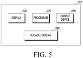
- FIG. 5 is a block diagram schematically illustrating a configuration of an electronic device according to an embodiment.
- an electronic device 201 may include a processor 220, memory 230, an output device 250, and a slidable display 260.
- the electronic device 201 may be implemented to be identical or similar to the electronic device 100 or 100-1.
- the electronic device 201 may extend or contract the slidable display 260 according to either the first type or the second type of FIG. 4B .
- the processor 220 may control the overall operation of the electronic device 201.
- the processor 220 may display a screen including content on the slidable display 260.
- the content may be content stored in the memory 230.
- the screen may include a home screen, an execution screen of an application, and a standby screen.
- the screen may be displayed in the entire display area of the slidable display 260.
- the screen may be displayed only in a portion of the display area of the slidable display 260.
- the processor 220 may identify an event in which the slidable display 260 automatically extends or contracts by a designated size.
- the event may include a command to automatically extend or contract the slidable display 260 by the designated size in response to a user input.
- a plurality of events in which the slidable display 260 automatically extends or contracts by the designated size may be designated.
- Each of the plurality of events may include a command to automatically extend or contract the slidable display 260 by the designated size.
- the event may include a command to execute an application (or a specific function or specific content (e.g., image, video)) selected by a user input among a plurality of applications stored in the memory 230.
- the event may include a command to request a screen change to the home screen.
- the processor 220 may identify the designated size corresponding to the event. For example, if the event is identified, the processor 220 may identify the designated size indicating how much the slidable display 260 is automatically extended or contracted based on the event.
- the processor 220 may display an object for indicating the progress degree of extension or contraction of the slidable display 260 on the slidable display 260 based on the identified event.
- the processor 220 may determine the size of the object displayed on the slidable display 260 based on the designated size corresponding to the identified event.
- the processor 220 may determine the size of the object based on the size of the display area of the slidable display 260 when the extension or contraction of the slidable display 260 is completed. For example, as the size in which the slidable display 260 is enlarged increases, the size of the object may also increase. Alternatively, as the size in which the slidable display 260 is enlarged decreases, the size of the object may also decrease.
- the processor 220 may display a contracted screen of the screen displayed on the slidable display 260 on the object.
- the processor 220 may determine at least one of the shape or form of the object based on the direction of the extension or the contraction of the slidable display 260. For example, when the slidable display 260 is enlarged in the right direction (or left direction), the processor 220 may determine the shape or form of the object to indicate that it is enlarged in the right direction (or left direction). Alternatively, the processor 220 may determine the shape or form of the object to indicate that the slidable display 260 is enlarged in the upper direction (or in the lower direction) when it is enlarged in the upper direction (or in the lower direction).
- the processor 220 may apply a visual effect indicating the progress degree of extension or contraction of the slidable display 260 to the object displayed on the slidable display 260 while extending or reducing the slidable display 260 by the size designated in the identified event.
- the visual effect may include a specific color and/or blur effect displayed to overlap the object.
- the processor 220 may apply a visual effect so that the color or blur effect corresponding to the progress degree of extension or contraction of the slidable display 260 overlaps the object.
- the processor 220 may apply a visual effect so that as the slidable display 260 is extended or contracted, the area in which the color or blur effect is displayed on the object increases.
- the processor 220 may apply a visual effect so that as the extension or contraction of the slidable display 260 proceeds, the area in which the color or blur effect is displayed on the object decreases.
- the processor 220 may adjust the brightness of the color or blur effect displayed on the object according to the progress degree of extension or contraction of the slidable display 260. For example, the processor 220 may increase or decrease the color or blur effect displayed on the object according to the progress degree of extension or contraction of the slidable display 260.
- the processor 220 may display information about the remaining time until the extension or contraction is completed on the slidable display 260 based on the progress degree of the extension or contraction of the slidable display 260. For example, the processor 220 may display the remaining time based on the remaining size compared to the total size to be extended or contracted.
- the processor 220 may display information indicating the progress rate for the extension or contraction on the slidable display 260 based on the progress degree of extension or contraction of the slidable display 260. For example, the processor 220 may display the remaining size compared to the total size to be extended or contracted, as a percentage (%).
- the memory 230 may store content.
- the memory 230 may include a non-transitory recording medium capable of storing instructions that may be executed by the processor 220.
- the output device 250 may output at least one of visual (e.g., light), auditory (e.g., sound), and tactile (e.g., vibration).
- the processor 220 may output sound or vibration indicating the progress degree of extension or contraction of the slidable display 260 through the output device 250.
- the slidable display 260 may be implemented as a display capable of extending or contracting through a sliding operation.
- the slidable display 260 may be implemented as a rollable display.
- the slidable display 260 may extend or contract the size of the display area under the control of the processor 220.
- the operation of extending the display area of the slidable display 260 may mean an operation of rolling out the slidable display 260.
- the operation of contracting the display area of the slidable display 260 may mean an operation of rolling in the slidable display 260.
- the slidable display 260 may display a screen including content under the control of the processor 220.
- the processor 220 may adjust the size of the screen according to the extended or contracted display area. Alternatively, the processor 220 may adjust the size of the screen to suit the extended or contracted display area in real-time while the display area of the slidable display 260 is extended or contracted.
- FIG. 6A is a flowchart illustrating a method for displaying an object indicating a progress degree of extending or contracting a slidable display by an electronic device according to an embodiment.
- an electronic device may display a screen including content on a slidable display (the slidable display 260 of FIG. 5 ).
- the electronic device 201 may identify an event in which the slidable display 260 automatically extends or contracts by a designated size. For example, if an event requesting the execution of a specific application or a specific function is identified, the electronic device 201 may automatically extend or contract the slidable display 260 by the size designated in the event.
- the electronic device 201 may apply a visual effect indicating the progress degree of the extension or contraction to the object while extending or reducing the slidable display 260 by the designated size.
- the electronic device 201 may apply the visual effect to the object so as to correspond to the display area of the extended or contracted slidable display 260.
- the area of the visual effect applied to the object may also be gradually extended or contracted.
- the electronic device 201 may apply a visual effect indicating the progress degree of extension or contraction to the object displayed on the slidable display 260 until the extension or contraction of the slidable display 260 is completed. Through this, the electronic device 201 may inform the user of the progress degree (e.g., progress state and remaining time) of the extension or contraction of the slidable display 260.
- the electronic device 201 may effectively provide information indicating the progress state of extension or contraction of the slidable display 260 by applying the visual effect indicating the progress degree of the object in real-time. Further, since the size of the object is determined based on the size of the display area when the slidable display 260 is extended or contracted by the designated size, the electronic device 201 may effectively provide the progress degree (e.g., progress state and/or progress time) of extension or contraction of the slidable display 260 by the event.
- the progress degree e.g., progress state and/or progress time
- FIG. 6B is a flowchart illustrating a method for determining a shape of an object according to a progress direction of extending or contracting a slidable display by an electronic device according to an embodiment.
- the electronic device may identify the direction in which the slidable display (e.g., the display 260 of FIG. 5 ) is extended or contracted.
- the electronic device 201 may identify the direction in which the slidable display 260 is extended or contracted based on the type of event.
- the electronic device 201 may identify the progress direction of the slidable display 260 according to whether the current display area of the slidable display 260 is in an extended state or a contracted state.
- the electronic device 201 may determine the shape or form of an object displayed on the slidable display based on the identified direction. For example, when the slidable display 260 is extended in the right direction (or left direction), the electronic device 201 may determine to indicate that the shape or form of the object is extended in the right direction (or left direction). Alternatively, when the slidable display 260 is extended in the upper direction (or lower direction), the processor 220 may determine to indicate that the shape or form of the object is extended in the upper direction (or lower direction). Further, the electronic device 201 may determine a visual effect applied to the object based on the identified direction.
- the electronic device 201 may determine the visual effect to be able to indicate that is extended in the right direction (or left direction).
- the electronic device 201 may determine the visual effect to be able to indicate that it is extended in the upper direction (or lower direction).
- FIGS. 7A to 7D are views illustrating a method for displaying an object indicating a progress degree of extending or contracting a slidable display by an electronic device according to an embodiment.
- the electronic device 201 may display a first object 710 for indicating the progress degree of the extension when the slidable display 260 is extended in one direction (e.g., the right direction).
- the operation of extending the slidable display 260 may mean a slide-out (or roll-out) operation.
- the size (and shape) of the first object 710 may be determined based on the size of the display area of the slidable display 260 extended by the size designated in the event (e.g., an event that automatically extends the display area of the slidable display 260 by the designated size). For example, if an event of extending the slidable display 260 in the right direction is identified, the electronic device 201 may display the first object 710 in the form of extending in the right direction.
- the electronic device 201 may apply a visual effect to the first area 711 of the first object 710 corresponding to the current display area of the slidable display 260.
- the visual effect may mean displaying a designated color, overlapping the first area 711.
- the electronic device 201 may apply a visual effect to the third area 731 corresponding to the contracted display area of the slidable display 260 while the slidable display 260 is contracted in one direction.
- the visual effect-applied third area 731 may be reduced as compared to before contracted.
- the visual effect-applied third area 731 may be contracted in the left direction (or the direction in which the slidable display 260 is contracted).
- the electronic device 201 may apply a visual effect to the first area 751 of the third object 750 corresponding to the current display area of the slidable display 260.
- the visual effect may mean displaying a designated color, overlapping the first area 751.
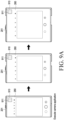
- FIGS. 9A and 9B are views illustrating a method for determining a size of an object based on an event by an electronic device according to an embodiment.
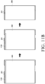
- FIGS. 11A and 11B are views illustrating a method for adjusting a length of an object according to a progress degree of extending or contracting a slidable display by an electronic device according to an embodiment.
- the electronic device 201 may identify an event of automatically enlarging (or extending) the slidable display 260. if an event is identified, the electronic device 201 may start the operation of extending the slidable display 260 by a designated size corresponding to the event. In this case, if the event is identified, the electronic device 201 may display an object 1110 having a designated color on the slidable display 260 based on the designated size corresponding to the event. For example, the object 1110 may be implemented in a bar shape. For example, the length of the object 1110 may be determined based on the designated size corresponding to the event. Meanwhile, in FIG. 11A , bar-shaped objects 1110 are displayed in two lines for convenience of description, but this is merely an example and the technical spirit of the present invention may not be limited thereto.
- the electronic device 201 may reduce the length of the object 1110 based on the progress degree of extension of the slidable display 260.
- the length of the object 1110 may correspond to a time required for the extension of the slidable display 260 to be completed.
- the electronic device 201 may inform the user of the progress degree (e.g., progress state and remaining time) of the extension of the slidable display 260.
- the electronic device 201 may no longer display the object 1110 on the slidable display 260.
- the electronic device 201 may identify an event of automatically contracting the slidable display 260. if the event is identified, the electronic device 201 may start an operation of reducing the slidable display 260 by the designated size corresponding to the event. In this case, if the event is identified, the electronic device 201 may display an object 1120 having a designated color on the slidable display 260 based on the designated size corresponding to the event.
- the object 1120 may be implemented in a bar shape.
- the length of an object1120 may be determined based on the size of the current display area of the slidable display 260. Alternatively, on the other hand, the length of object 1120 may be designated in advance.
- bar-shaped objects 1110 are displayed in one line for convenience of description, but this is merely an example and the technical spirit of the present invention may not be limited thereto.
- the electronic device 201 may reduce the length of the object 1120 based on the progress degree of contraction of the slidable display 260.
- the length of the object 1120 may correspond to a time required for the contraction of the slidable display 260 to be completed.
- the electronic device 201 may inform the user of the progress degree of the contraction of the slidable display 260.
- the electronic device 201 may no longer display the object 1120 on the slidable display 260.
- FIG. 12 is a view illustrating a method for adjusting a length of an object in a border shape according to a progress degree of extending or contracting a slidable display by an electronic device according to an embodiment.
- the electronic device 201 may reduce the length of the object 1210 based on the progress degree of contraction of the slidable display 260.
- the length of the object 1210 may be decreased with respect to the first point 1211.
- the length of the object 1210 may correspond to a time required for the contraction of the slidable display 260 to be completed.
- the electronic device 201 may inform the user of the progress degree of the contraction of the slidable display 260.
- the electronic device 201 may display an object 1220 having a designated color in the entire edge area of the slidable display 260. Accordingly, the electronic device 201 may inform the user that the contraction of the slidable display 260 is completed.
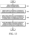
- FIG. 13 is a flowchart illustrating a method for applying a visual effect on a screen displayed on a slidable display according to a progress degree of extending or contracting the slidable display by an electronic device according to an embodiment.
- the electronic device 201 may identify an event in which the slidable display 260 automatically extends or contracts by a designated size.
- the electronic device 201 may display a visual effect (e.g., blur or masking) indicating the progress degree of extension or contraction of the slidable display 260 on the screen based on the identified event.
- a visual effect e.g., blur or masking
- the electronic device 201 may apply a visual effect (e.g., blur or masking) to overlap the screen including the content.
- the electronic device 201 may adjust the area to which the visual effect (e.g., blur or masking) is applied on the screen according to the progress degree of the extension or contraction of the slidable display 260.
- the area to which the visual effect is applied may correspond to the time required for the slidable display 260 to complete the extension or contraction.
- the electronic device 201 may inform the user of the progress degree of the contraction of the slidable display 260 through the visual effect applied on the screen.
- the electronic device 201 may no longer apply the visual effect on the screen displayed on the slidable display 260. Accordingly, the electronic device 201 may inform the user that the extension or contraction of the slidable display 260 is completed.
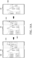
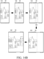
- FIGS. 14A and 14B are views illustrating a method for applying a visual effect on a screen displayed on a slidable display according to a progress degree of extending or contracting the slidable display by an electronic device according to an embodiment.
- the electronic device 201 may display a screen 1405 including content on a slidable display (e.g., the slidable display 260 of FIG. 5 ).
- a slidable display e.g., the slidable display 260 of FIG. 5 .
- the electronic device 201 may identify an event in which the slidable display 260 automatically contracts by a designated size.
- the electronic device 201 may display a visual effect indicating the progress degree of the contraction of the slidable display 260 in the first area 1410 of the screen 1405 based on the identified event.
- the electronic device 201 may blur the first area 1410 of the screen 1405 or mask the first area of the screen 1405.
- the first area 1410 may be an area that is rolled in of the display area of the slidable display 260 by the contraction of the slidable display 260.
- the area to which the visual effect is applied may also be contracted. if the contraction of the slidable display 260 is completed, the electronic device 201 may no longer apply the visual effect to the screen 1405. Further, the electronic device 201 may display a screen 1406 resized to fit the display area of the contracted slidable display 260.
- the electronic device 201 may display a screen 1415 including content on a slidable display (e.g., the slidable display 260 of FIG. 5 ).
- a slidable display e.g., the slidable display 260 of FIG. 5 .
- FIGS. 15A and 15B are views illustrating a method for displaying an object indicating a progress degree of extending or contracting a slidable display based on an event by an electronic device according to an embodiment.
- the electronic device 201 may enlarge the display area of the slidable display 260 according to execution of the camera application. For example, the electronic device 201 may identify the size of the display area of the slidable display 260 to be enlarged according to the execution of the camera application.
- the electronic device 201 may display the first object 1520 on the execution screen 1515 while the slidable display 260 is extended.
- the electronic device 201 may apply a visual effect to the first object 1520 according to the progress degree of extension of the slidable display 260. For example, as the slidable display 260 is extended, an area in which the visual effect is displayed on the first object 1520 may also be increased.
- the audio module 1670 may convert a sound into an electrical signal and vice versa. According to an embodiment, the audio module 1670 may obtain the sound via the input module 1650, or output the sound via the sound output module 1655 or a headphone of an external electronic device (e.g., an electronic device 1602) directly (e.g., wiredly) or wirelessly coupled with the electronic device 1601.
- an external electronic device e.g., an electronic device 1602
- directly e.g., wiredly
- wirelessly e.g., wirelessly
- the sensor module 1676 may detect an operational state (e.g., power or temperature) of the electronic device 1601 or an environmental state (e.g., a state of a user) external to the electronic device 101, and then generate an electrical signal or data value corresponding to the detected state.
- the sensor module 1676 may include, for example, a gesture sensor, a gyro sensor, an atmospheric pressure sensor, a magnetic sensor, an accelerometer, a grip sensor, a proximity sensor, a color sensor, an infrared (IR) sensor, a biometric sensor, a temperature sensor, a humidity sensor, or an illuminance sensor.
- the camera module 1680 may capture a still image or moving images.
- the camera module 1680 may include one or more lenses, image sensors, image signal processors, or flashes.
- At least some of the above-described components may be coupled mutually and communicate signals (e.g., commands or data) therebetween via an inter-peripheral communication scheme (e.g., a bus, general purpose input and output (GPIO), serial peripheral interface (SPI), or mobile industry processor interface (MIPI)).
- an inter-peripheral communication scheme e.g., a bus, general purpose input and output (GPIO), serial peripheral interface (SPI), or mobile industry processor interface (MIPI)
- an electronic device 201 may comprise a slidable display 260 and a processor 220.
- the processor may be configured to display a screen including content on the slidable display.
- the processor may be configured to identify an event for automatically extending or contracting the slidable display by a designated size. The designated size may be determined based on the event.
- the processor may be configured to display an object for indicating a progress degree of extending or contracting the slidable display on the slidable display based on the event. The size of the object may be determined based on the designated size.
- the processor may be configured to apply a visual effect indicating the progress degree to the object while extending or contracting the slidable display by the designated size.
- the processor may be configured to apply the visual effect to allow a color or blur effect corresponding to the progress degree to overlap the object.
- the processor may be configured to display information about a remaining time on the slidable display until the extension or the contraction is completed based on the progress degree.
- the processor may be configured to display information indicating a progress rate for the extension or the contraction on the slidable display based on the progress degree.
- the processor may be configured to determine a size of the object based on a size of a display area of the slidable display when the extension or the contraction of the slidable display is completed.
Landscapes
- Engineering & Computer Science (AREA)
- Theoretical Computer Science (AREA)
- Physics & Mathematics (AREA)
- General Engineering & Computer Science (AREA)
- Human Computer Interaction (AREA)
- General Physics & Mathematics (AREA)
- Computer Hardware Design (AREA)
- Signal Processing (AREA)
- Mathematical Physics (AREA)
- Environmental & Geological Engineering (AREA)
- Computer Networks & Wireless Communication (AREA)
- Telephone Set Structure (AREA)
- User Interface Of Digital Computer (AREA)
Applications Claiming Priority (3)
| Application Number | Priority Date | Filing Date | Title |
|---|---|---|---|
| KR20220110439 | 2022-09-01 | ||
| KR1020220129011A KR20240031828A (ko) | 2022-09-01 | 2022-10-07 | 슬라이더블 디스플레이를 포함하는 전자 장치와 이의 동작 방법 |
| PCT/KR2023/013091 WO2024049270A1 (fr) | 2022-09-01 | 2023-09-01 | Dispositif électronique comprenant une unité d'affichage coulissante et son procédé de fonctionnement |
Publications (2)
| Publication Number | Publication Date |
|---|---|
| EP4580170A1 true EP4580170A1 (fr) | 2025-07-02 |
| EP4580170A4 EP4580170A4 (fr) | 2025-10-22 |
Family
ID=90098400
Family Applications (1)
| Application Number | Title | Priority Date | Filing Date |
|---|---|---|---|
| EP23860945.7A Pending EP4580170A4 (fr) | 2022-09-01 | 2023-09-01 | Dispositif électronique comprenant une unité d'affichage coulissante et son procédé de fonctionnement |
Country Status (4)
| Country | Link |
|---|---|
| US (1) | US20250190016A1 (fr) |
| EP (1) | EP4580170A4 (fr) |
| CN (1) | CN119856479A (fr) |
| WO (1) | WO2024049270A1 (fr) |
Family Cites Families (8)
| Publication number | Priority date | Publication date | Assignee | Title |
|---|---|---|---|---|
| US9383775B2 (en) * | 2012-02-07 | 2016-07-05 | Lg Electronics Inc. | Icon display method for a pull-out display device |
| KR102047690B1 (ko) * | 2013-01-24 | 2019-11-22 | 엘지전자 주식회사 | 포터블 디바이스 및 그의 제어 방법 |
| KR20140135404A (ko) * | 2013-05-16 | 2014-11-26 | 엘지전자 주식회사 | 포터블 디바이스 및 그 제어 방법 |
| KR102274156B1 (ko) * | 2013-08-26 | 2021-07-07 | 삼성전자주식회사 | 윈도우 영역 조정 방법 및 그에 따른 전자 장치 |
| KR102359544B1 (ko) * | 2015-06-22 | 2022-02-08 | 엘지전자 주식회사 | 변형 가능한 디스플레이 장치 및 그의 동작 방법 |
| KR102485147B1 (ko) * | 2015-07-06 | 2023-01-06 | 엘지전자 주식회사 | 변형 가능한 디스플레이 장치 및 그의 동작 방법 |
| KR102266152B1 (ko) * | 2018-02-22 | 2021-06-17 | 삼성전자주식회사 | 디스플레이 영역의 크기 변경이 가능한 플렉시블 디스플레이를 포함하는 전자 장치 및 그 제어 방법 |
| KR102256042B1 (ko) * | 2020-10-13 | 2021-05-25 | 삼성전자 주식회사 | 입력을 유도하는 전자 장치 및 방법. |
-
2023
- 2023-09-01 CN CN202380063259.8A patent/CN119856479A/zh active Pending
- 2023-09-01 WO PCT/KR2023/013091 patent/WO2024049270A1/fr not_active Ceased
- 2023-09-01 EP EP23860945.7A patent/EP4580170A4/fr active Pending
-
2025
- 2025-02-24 US US19/061,767 patent/US20250190016A1/en active Pending
Also Published As
| Publication number | Publication date |
|---|---|
| CN119856479A (zh) | 2025-04-18 |
| EP4580170A4 (fr) | 2025-10-22 |
| WO2024049270A1 (fr) | 2024-03-07 |
| US20250190016A1 (en) | 2025-06-12 |
Similar Documents
| Publication | Publication Date | Title |
|---|---|---|
| EP4191384B1 (fr) | Dispositif électronique à affichage flexible et procédé de fonctionnement dudit dispositif | |
| EP4191383A1 (fr) | Dispositif électronique à affichage flexible et procédé de fonctionnement dudit dispositif | |
| US12578762B2 (en) | Electronic device including sliding structure and flexible display with audio data adjustment | |
| US12360648B2 (en) | Electronic device comprising flexible display, and method for operating same | |
| US12457697B2 (en) | Flexible display, structure supporting the flexible display, and electronic device including the same | |
| US12191934B2 (en) | Electronic device including flexible display and method of operating the same | |
| US12386392B2 (en) | Electronic device including flexible display, and control method therefor | |
| US20230247130A1 (en) | Method for providing screen by using flexible display, and electronic device supporting same | |
| EP4328707A1 (fr) | Ensemble de connexion comprenant une carte de circuit imprimé souple, et dispositif électronique comprenant celui-ci | |
| US20250168269A1 (en) | Electronic device for reconstructing background image | |
| US20250140496A1 (en) | Rollable electronic device comprising button structure | |
| US20240314236A1 (en) | Electronic device, and method by which electronic device displays display mode information on basis of context information | |
| US12613560B2 (en) | Electronic apparatus including microphone and control method therefor | |
| KR102899581B1 (ko) | 플렉서블 디스플레이를 포함하는 전자 장치와 이의 동작 방법 | |
| EP4580170A1 (fr) | Dispositif électronique comprenant une unité d'affichage coulissante et son procédé de fonctionnement | |
| CN118119916A (zh) | 用于通过使用传感器识别状态的电子设备 | |
| EP4239440B1 (fr) | Dispositif électronique comprenant un dispositif d'affichage flexible et procédé de capture d'image dans un dispositif électronique | |
| US20250044830A1 (en) | Electronic device comprising flexible display, and method for adjusting size of display in electronic device | |
| EP4496300A1 (fr) | Dispositif électronique comprenant un dispositif d'affichage flexible, et procédé de fonctionnement associé | |
| US20250201159A1 (en) | Electronic device including flexible display and method for controlling same | |
| KR102959925B1 (ko) | 플렉서블 디스플레이를 포함하는 전자 장치와 이의 동작 방법 | |
| KR20240031828A (ko) | 슬라이더블 디스플레이를 포함하는 전자 장치와 이의 동작 방법 | |
| KR20230007791A (ko) | 플렉서블 디스플레이를 포함하는 전자 장치와 이의 동작 방법 | |
| KR20220068869A (ko) | 플렉서블 디스플레이를 포함하는 전자 장치 및 그 동작 방법 | |
| KR20220078433A (ko) | 플렉서블 디스플레이를 포함하는 전자 장치 및 상기 전자 장치에서 이미지를 촬영하는 방법 |
Legal Events
| Date | Code | Title | Description |
|---|---|---|---|
| STAA | Information on the status of an ep patent application or granted ep patent |
Free format text: STATUS: THE INTERNATIONAL PUBLICATION HAS BEEN MADE |
|
| PUAI | Public reference made under article 153(3) epc to a published international application that has entered the european phase |
Free format text: ORIGINAL CODE: 0009012 |
|
| STAA | Information on the status of an ep patent application or granted ep patent |
Free format text: STATUS: REQUEST FOR EXAMINATION WAS MADE |
|
| 17P | Request for examination filed |
Effective date: 20250328 |
|
| AK | Designated contracting states |
Kind code of ref document: A1 Designated state(s): AL AT BE BG CH CY CZ DE DK EE ES FI FR GB GR HR HU IE IS IT LI LT LU LV MC ME MK MT NL NO PL PT RO RS SE SI SK SM TR |
|
| A4 | Supplementary search report drawn up and despatched |
Effective date: 20250924 |
|
| RIC1 | Information provided on ipc code assigned before grant |
Ipc: H04M 1/72454 20210101AFI20250918BHEP Ipc: H04M 1/02 20060101ALI20250918BHEP Ipc: G06F 3/041 20060101ALI20250918BHEP Ipc: G06F 3/04845 20220101ALI20250918BHEP Ipc: G06F 3/0481 20220101ALI20250918BHEP Ipc: G06F 1/16 20060101ALI20250918BHEP Ipc: G09G 3/00 20060101ALI20250918BHEP Ipc: G09G 5/00 20060101ALI20250918BHEP |
|
| DAV | Request for validation of the european patent (deleted) | ||
| DAX | Request for extension of the european patent (deleted) |