EP4580182A2 - Codierungsverfahren und vorrichtung dafür sowie decodierungsverfahren und vorrichtung dafür - Google Patents
Codierungsverfahren und vorrichtung dafür sowie decodierungsverfahren und vorrichtung dafür Download PDFInfo
- Publication number
- EP4580182A2 EP4580182A2 EP25176766.1A EP25176766A EP4580182A2 EP 4580182 A2 EP4580182 A2 EP 4580182A2 EP 25176766 A EP25176766 A EP 25176766A EP 4580182 A2 EP4580182 A2 EP 4580182A2
- Authority
- EP
- European Patent Office
- Prior art keywords
- coding unit
- coding
- unit
- split
- coding units
- Prior art date
- Legal status (The legal status is an assumption and is not a legal conclusion. Google has not performed a legal analysis and makes no representation as to the accuracy of the status listed.)
- Pending
Links
Images







Classifications
-
- H—ELECTRICITY
- H04—ELECTRIC COMMUNICATION TECHNIQUE
- H04N—PICTORIAL COMMUNICATION, e.g. TELEVISION
- H04N19/00—Methods or arrangements for coding, decoding, compressing or decompressing digital video signals
- H04N19/10—Methods or arrangements for coding, decoding, compressing or decompressing digital video signals using adaptive coding
- H04N19/134—Methods or arrangements for coding, decoding, compressing or decompressing digital video signals using adaptive coding characterised by the element, parameter or criterion affecting or controlling the adaptive coding
- H04N19/136—Incoming video signal characteristics or properties
-
- H—ELECTRICITY
- H04—ELECTRIC COMMUNICATION TECHNIQUE
- H04N—PICTORIAL COMMUNICATION, e.g. TELEVISION
- H04N19/00—Methods or arrangements for coding, decoding, compressing or decompressing digital video signals
- H04N19/10—Methods or arrangements for coding, decoding, compressing or decompressing digital video signals using adaptive coding
- H04N19/102—Methods or arrangements for coding, decoding, compressing or decompressing digital video signals using adaptive coding characterised by the element, parameter or selection affected or controlled by the adaptive coding
- H04N19/103—Selection of coding mode or of prediction mode
- H04N19/105—Selection of the reference unit for prediction within a chosen coding or prediction mode, e.g. adaptive choice of position and number of pixels used for prediction
-
- H—ELECTRICITY
- H04—ELECTRIC COMMUNICATION TECHNIQUE
- H04N—PICTORIAL COMMUNICATION, e.g. TELEVISION
- H04N19/00—Methods or arrangements for coding, decoding, compressing or decompressing digital video signals
- H04N19/10—Methods or arrangements for coding, decoding, compressing or decompressing digital video signals using adaptive coding
- H04N19/102—Methods or arrangements for coding, decoding, compressing or decompressing digital video signals using adaptive coding characterised by the element, parameter or selection affected or controlled by the adaptive coding
- H04N19/117—Filters, e.g. for pre-processing or post-processing
-
- H—ELECTRICITY
- H04—ELECTRIC COMMUNICATION TECHNIQUE
- H04N—PICTORIAL COMMUNICATION, e.g. TELEVISION
- H04N19/00—Methods or arrangements for coding, decoding, compressing or decompressing digital video signals
- H04N19/10—Methods or arrangements for coding, decoding, compressing or decompressing digital video signals using adaptive coding
- H04N19/102—Methods or arrangements for coding, decoding, compressing or decompressing digital video signals using adaptive coding characterised by the element, parameter or selection affected or controlled by the adaptive coding
- H04N19/12—Selection from among a plurality of transforms or standards, e.g. selection between discrete cosine transform [DCT] and sub-band transform or selection between H.263 and H.264
- H04N19/122—Selection of transform size, e.g. 8x8 or 2x4x8 DCT; Selection of sub-band transforms of varying structure or type
-
- H—ELECTRICITY
- H04—ELECTRIC COMMUNICATION TECHNIQUE
- H04N—PICTORIAL COMMUNICATION, e.g. TELEVISION
- H04N19/00—Methods or arrangements for coding, decoding, compressing or decompressing digital video signals
- H04N19/10—Methods or arrangements for coding, decoding, compressing or decompressing digital video signals using adaptive coding
- H04N19/102—Methods or arrangements for coding, decoding, compressing or decompressing digital video signals using adaptive coding characterised by the element, parameter or selection affected or controlled by the adaptive coding
- H04N19/132—Sampling, masking or truncation of coding units, e.g. adaptive resampling, frame skipping, frame interpolation or high-frequency transform coefficient masking
-
- H—ELECTRICITY
- H04—ELECTRIC COMMUNICATION TECHNIQUE
- H04N—PICTORIAL COMMUNICATION, e.g. TELEVISION
- H04N19/00—Methods or arrangements for coding, decoding, compressing or decompressing digital video signals
- H04N19/10—Methods or arrangements for coding, decoding, compressing or decompressing digital video signals using adaptive coding
- H04N19/134—Methods or arrangements for coding, decoding, compressing or decompressing digital video signals using adaptive coding characterised by the element, parameter or criterion affecting or controlling the adaptive coding
- H04N19/157—Assigned coding mode, i.e. the coding mode being predefined or preselected to be further used for selection of another element or parameter
- H04N19/159—Prediction type, e.g. intra-frame, inter-frame or bidirectional frame prediction
-
- H—ELECTRICITY
- H04—ELECTRIC COMMUNICATION TECHNIQUE
- H04N—PICTORIAL COMMUNICATION, e.g. TELEVISION
- H04N19/00—Methods or arrangements for coding, decoding, compressing or decompressing digital video signals
- H04N19/10—Methods or arrangements for coding, decoding, compressing or decompressing digital video signals using adaptive coding
- H04N19/169—Methods or arrangements for coding, decoding, compressing or decompressing digital video signals using adaptive coding characterised by the coding unit, i.e. the structural portion or semantic portion of the video signal being the object or the subject of the adaptive coding
- H04N19/17—Methods or arrangements for coding, decoding, compressing or decompressing digital video signals using adaptive coding characterised by the coding unit, i.e. the structural portion or semantic portion of the video signal being the object or the subject of the adaptive coding the unit being an image region, e.g. an object
- H04N19/176—Methods or arrangements for coding, decoding, compressing or decompressing digital video signals using adaptive coding characterised by the coding unit, i.e. the structural portion or semantic portion of the video signal being the object or the subject of the adaptive coding the unit being an image region, e.g. an object the region being a block, e.g. a macroblock
-
- H—ELECTRICITY
- H04—ELECTRIC COMMUNICATION TECHNIQUE
- H04N—PICTORIAL COMMUNICATION, e.g. TELEVISION
- H04N19/00—Methods or arrangements for coding, decoding, compressing or decompressing digital video signals
- H04N19/85—Methods or arrangements for coding, decoding, compressing or decompressing digital video signals using pre-processing or post-processing specially adapted for video compression
- H04N19/86—Methods or arrangements for coding, decoding, compressing or decompressing digital video signals using pre-processing or post-processing specially adapted for video compression involving reduction of coding artifacts, e.g. of blockiness
Definitions
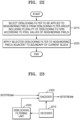
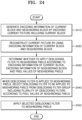
- a video decoding method of applying a deblocking filter to neighboring pixels adjacent to a boundary of a current block including selecting a deblocking filter to be applied to the neighboring pixels from among a plurality of deblocking filters according to pixel values of the neighboring pixels and a size of the current block, and applying the selected deblocking filter to the neighboring pixels, wherein the plurality of deblocking filters include three or more deblocking filters having different ranges of neighboring pixels to which deblocking filtering is applied.
- unit used herein should be understood as software or a hardware component, such as a FPGA or an ASIC, which performs certain functions. However, the term “unit” is not limited to software or hardware.
- the term “unit” may be configured to be stored in an addressable storage medium or to reproduce one or more processors. Thus, the term “unit” may include, for example, components, such as software components, object-oriented software components, class components, and task components, processes, functions, attributes, procedures, subroutines, segments of program code, drivers, firmware, microcode, a circuit, data, database, data structures, tables, arrays, and parameters. Functions provided in components and “units” may be combined to a small number of components and “units” or may be divided into subcomponents and "sub-units”.
- current block refers to a coding unit, a prediction unit, or a transform unit that is being currently encoded or decoded.
- current coding block current prediction block
- current transform block current transform block
- sample when used herein, refers to data allocated to a sampling position of an image, i.e., data to be processed.
- samples may be pixel values in a spatial domain, and transform coefficients in a transform domain.
- a unit including at least one sample may be defined as a block.
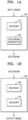
- the image encoding apparatus 100 includes an encoder 110 and a bitstream generator 120.
- the encoder 110 splits a picture or a slice included in the picture into a plurality of largest coding units according to a size of the largest coding units.
- the largest coding units may be data units having a size of 32x32, 64x64, 128x128, 256x256 or the like, and may be square data units, the horizontal and vertical sizes of which are 2 2 .
- the encoder 110 may provide the bitstream generator 120 with largest coding unit size information indicating the size of the largest coding units.
- the bitstream generator 120 may include the largest coding unit size information in a bitstream.
- the encoder 110 determines coding units by splitting a largest coding unit. Whether to split a coding unit is determined according to whether it is efficient to split the coding unit by rate-distortion optimization. In addition, split information indicating whether the coding unit is split may be generated. The split information may be expressed in the form of a flag.
- a coding unit may be split in various ways. For example, a square coding unit may be split into four square coding units, the width and height of which are half those of the square coding unit. The square coding unit may be split into two rectangular coding units having a width half that of the square coding unit. The square coding unit may be split into two rectangular coding units having a height half that of the square coding unit. The square coding unit may be split into three coding units by splitting the width or height thereof into a ratio of 1:2:1.
- a rectangular coding unit having a width twice a height thereof may be split into two square coding units.
- a rectangular coding unit having a width twice a height thereof may be split into two square coding units having a width four times a height thereof.
- a rectangular coding unit having a width twice a height thereof may be split into two rectangular coding units and one square coding unit by splitting the width of the rectangular coding unit into a ratio of 1:2:1.
- a rectangular coding unit having a height twice a width thereof may be split into two square coding units.
- a rectangular coding unit having a height twice a width thereof may be split into two rectangular coding units having a height four times a width thereof.
- a rectangular coding unit having a height twice a width thereof may be split into two rectangular coding units and one square coding unit by splitting the height of the rectangular coding unit into a ratio of 1:2:1.
- information about a split method applicable to a coding unit among the split methods applicable to the image encoding apparatus 100 may be determined for each picture. Thus, it may be determined that only specific split methods are applicable to each picture.
- information regarding a split method applicable to a coding unit is not additionally determined.
- a coding unit of a specific size may be split by a specific split method. For example, when a coding unit has a size of 256x265, the coding unit may be set to be split into only four square coding units having a width and a height which are half those of the coding unit.
- split type information indicating a splitting method of the coding unit may be generated.
- split type information may not be generated.
- split type information may not be generated.
- image data of a current picture is split into largest coding units according to a maximum size of a coding unit.
- a largest coding unit may include coding units hierarchically split therefrom.
- a form and position of a lower coding unit may be determined according to a form into which a higher coding unit is split.
- a minimum size of a coding unit that limits splitting of the coding unit may be set in advance.
- the encoder 110 compares coding efficiency when a coding unit is hierarchically split with coding efficiency when the coding unit is not split.
- the encoder 110 determines whether to split the coding unit according to a result of the comparison. When it is determined that it is more efficient to split the coding unit, the encoder 110 hierarchically splits the coding unit.
- the coding unit is not split when the result of the comparison reveals that it is efficient not to split the coding unit. Whether to split the coding unit may be determined independently of whether to split other coding units adjacent to the coding unit.
- a coding unit that is finally split may be predicted by intra prediction or inter prediction.
- Intra prediction is a method of predicting samples of a prediction unit by using reference samples neighboring the prediction unit.
- Inter prediction is a method of predicting samples of a prediction unit by obtaining a reference sample from a reference picture referenced for a current picture.
- the encoder 110 may select a most efficient intra prediction method by applying a plurality of intra prediction methods to a prediction unit.
- Intra prediction methods include a directional mode such as a DC mode, a planar mode, a vertical mode, and a horizontal mode.
- Intra prediction may be performed for each prediction unit when a reconstructed sample neighboring a coding unit is used as a reference sample.
- the reference sample in the coding unit should be reconstructed prior to prediction and thus a prediction order of the prediction units may be subordinate to a transformation order of transform units. Therefore, when the reconstructed sample in the coding unit is used as a reference sample, only an intra prediction method for transform units corresponding to the prediction units may be determined for the prediction units and intra prediction may be performed substantially for each of the transform units.
- the encoder 110 may select a most efficient inter prediction method by determining an optimal motion vector and an optimal reference picture. For inter prediction, the encoder 110 may determine a plurality of motion vector candidates from coding units spatially and temporally neighboring a current coding unit, and determine a most efficient motion vector as a motion vector among the plurality of motion vector candidates. Similarly, a plurality of reference picture candidates may be determined from the coding units spatially and temporally neighboring the current coding unit, and a most efficient reference picture may be determined among the plurality of reference picture candidates. In one embodiment, a reference picture may be determined from among reference picture lists determined in advance for a current picture.
- a most efficient motion vector among a plurality of motion vector candidates may be determined as a prediction motion vector and a motion vector may be determined by correcting the prediction motion vector.
- Inter prediction may be performed in parallel for each prediction unit included in a coding unit.
- the encoder 110 may reconstruct a coding unit by obtaining only information representing a motion vector and a reference picture according to a skip mode.
- a skip mode all encoding information, including a residual signal, is omitted except for the information representing the motion vector and the reference picture. Because the residual signal is omitted, the skip mode is applicable when prediction accuracy is very high.
- a partition mode may be limited according to a prediction method for a prediction unit. For example, only a partition mode for prediction units having sizes of 2Nx2N and NxN may be applied to intra prediction, whereas a partition mode for prediction units having sizes of 2Nx2N, 2NxN, Nx2N and NxN may be applied to inter prediction. Only a partition mode for a prediction unit having a size of 2Nx2N may be applied to a skip mode of inter prediction.
- a partition mode allowed for each prediction method in the image encoding apparatus 100 may be changed according to coding efficiency.
- the image encoding apparatus 100 may perform transformation based on a coding unit.
- the image encoding apparatus 100 may transform residual data, which is the differences between original values of pixels included in a coding unit and predicted values thereof, by a certain process.
- the image encoding apparatus 100 may perform lossy compression on the residual data by quantization and DCT/DST transformation.
- the image encoding apparatus 100 may perform lossless compression on the residual data without quantization.
- the encoder 110 determines a prediction method most efficient for a current coding unit among intra prediction methods and inter prediction methods.
- the encoder 110 determines a prediction method for the current coding unit according to coding efficiency according to a prediction result.
- the encoder 110 may determine a transformation method according to coding efficiency according to a transformation result. Coding efficiency of the coding unit is finally determined according to a most efficient prediction method and a most efficient transformation method for the coding unit.
- the encoder 110 determines a hierarchical structure of a largest coding unit according to coding efficiency of coding units finally split from the largest coding unit.
- the encoder 110 may measure coding efficiency of coding units, prediction efficiency of prediction methods, and the like by using Lagrangian multiplier-based rate-distortion optimization.
- the bitstream generator 120 may output information, which is generated by the encoder 110 according to the hierarchical structure of the largest coding unit, in the form of a bitstream.
- the image decoding apparatus 150 includes a receiver 160 and a decoder 180.
- the image decoding apparatus 150 is configured to restore image data and thus various encoding methods used in the image encoding apparatus 100 are applicable to the image decoding apparatus 150.
- the receiver 160 receives and parses a bitstream of an encoded video.
- the receiver 160 extracts information necessary to decode each largest coding unit from the parsed bitstream and provides the information to the decoder 170.
- the receiver 160 may extract information regarding a maximum size of a coding unit of a current picture from a header, a sequence parameter set, or a picture parameter set for the current picture.
- the receiver 160 extracts split information of coding units of a tree structure for each largest coding unit from the parsed bitstream.
- the extracted split information is output to the decoder 170.
- the decoder 170 may determine a tree structure of a largest coding unit by splitting the largest coding unit according to the extracted split information.
- the split information extracted by the receiver 160 is split information of a tree structure determined by the image encoding apparatus 100 to generate a minimum encoding error. Therefore, the image decoding apparatus 150 may reconstruct an image by decoding data according to an encoding method that generates the minimum encoding error.
- the receiver 160 may extract split information for a data unit, such as a prediction unit and a transform unit, which is included in a coding unit. For example, the receiver 160 may extract information regarding a most efficient partition mode for a prediction unit. The receiver 160 may extract transform partition information of a tree structure most efficient for a transform unit.
- the receiver 1600 may obtain information regarding a prediction method most efficient for prediction units split from a coding unit.
- the receiver 160 may obtain information regarding a transformation method most efficient for transform units split from a coding unit.
- the receiver 160 extracts information from the bitstream according to a method of configuring the bitstream by the bitstream generator 120 of the image encoding apparatus 100.
- the decoder 170 may split a largest coding unit into coding units of a most efficient tree structure, based on the split information.
- the decoder 170 may split a coding unit into prediction units according to information regarding a partition mode.
- the decoder 170 may split a coding unit into transform units according to the transform split information.
- the decoder 170 may predict a prediction unit according to information regarding a prediction method.
- the decoder 170 may perform inverse quantization and inverse transformation on residual data corresponding to the difference an original value and a predicted value of a pixel, based on information a method of transforming a transform unit.
- the decoder 170 may reconstruct pixels of a coding unit according to a result of predicting a prediction unit and a result of transforming a transform unit.
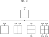
- FIG. 2 illustrates a process of determining at least one coding unit by splitting a current coding unit by the image decoding apparatus 150, according to an embodiment.
- the image decoding apparatus 150 may determine a shape of a coding unit by using block shape information, and may determine a splitting method of the coding unit by using split shape information. That is, a coding unit splitting method indicated by the split shape information may be determined based on a block shape indicated by the block shape information used by the image decoding apparatus 150.
- the image decoding apparatus 150 may use the block shape information indicating that the current coding unit has a square shape. For example, the image decoding apparatus 150 may determine whether not to split a square coding unit, whether to vertically split the square coding unit, whether to horizontally split the square coding unit, or whether to split the square coding unit into four coding units, based on the split shape information. Referring to FIG.
- the decoder 180 may determine that a coding unit 210a having the same size as the current coding unit 200 is not split, based on the split shape information indicating not to perform splitting, or may determine coding units 210b, 210c, or 210d split based on the split shape information indicating a predetermined splitting method.
- the image decoding apparatus 150 may determine two coding units 210b obtained by splitting the current coding unit 200 in a vertical direction, based on the split shape information indicating to perform splitting in a vertical direction.
- the image decoding apparatus 150 may determine two coding units 210c obtained by splitting the current coding unit 200 in a horizontal direction, based on the split shape information indicating to perform splitting in a horizontal direction.
- the image decoding apparatus 150 may determine four coding units 210d obtained by splitting the current coding unit 200 in vertical and horizontal directions, based on the split shape information indicating to perform splitting in vertical and horizontal directions.
- splitting methods of the square coding unit are not limited to the above-described methods, and the split shape information may indicate various methods. Predetermined splitting methods of splitting the square coding unit will be described in detail below in relation to various embodiments.
- FIG. 3 illustrates a process, performed by the image decoding apparatus 150, of determining at least one coding unit by splitting a non-square coding unit, according to an embodiment.
- the image decoding apparatus 150 may use block shape information indicating that a current coding unit has a non-square shape.
- the image decoding apparatus 150 may determine whether not to split the non-square current coding unit or whether to split the non-square current coding unit by using a predetermined splitting method, based on split shape information. Referring to FIG.
- the image decoding apparatus 150 may not split a coding unit 310 or 360 having the same size as the current coding unit 300 or 350, based on the split shape information indicating not to perform splitting, or determine coding units 320a and 320b, 330a to 330c, 370a and 370b, or 380a to 380c split based on the split shape information indicating a predetermined splitting method.
- Predetermined splitting methods of splitting a non-square coding unit will be described in detail below in relation to various embodiments.
- the image decoding apparatus 150 may determine a splitting method of a coding unit by using the split shape information and, in this case, the split shape information may indicate the number of one or more coding units generated by splitting a coding unit. Referring to FIG. 3 , when the split shape information indicates to split the current coding unit 300 or 350 into two coding units, the image decoding apparatus 150 may determine two coding units 320a and 320b, or 370a and 370b included in the current coding unit 300 or 350, by splitting the current coding unit 300 or 350 based on the split shape information.
- the image decoding apparatus 150 when the image decoding apparatus 150 splits the non-square current coding unit 300 or 350 based on the split shape information, the location of a long side of the non-square current coding unit 300 or 350 may be considered.
- the image decoding apparatus 150 may determine a plurality of coding units by splitting a long side of the current coding unit 300 or 350, in consideration of the shape of the current coding unit 300 or 350.
- the image decoding apparatus 150 may determine an odd number of coding units included in the current coding unit 300 or 350. For example, when the split shape information indicates to split the current coding unit 300 or 350 into three coding units, the image decoding apparatus 150 may split the current coding unit 300 or 350 into three coding units 330a, 330b, and 330c, or 380a, 380b, and 380c. According to an embodiment, the image decoding apparatus 150 may determine the odd number of coding units included in the current coding unit 300 or 350, and not all the determined coding units may have the same size.
- a predetermined coding unit 330b or 380b from among the determined odd number of coding units 330a, 330b, and 330c, or 380a, 380b, and 380c may have a size different from the size of the other coding units 330a and 330c, or 380a and 380c.
- coding units that may be determined by splitting the current coding unit 300 or 350 may have various types and sizes.
- the image decoding apparatus 150 may determine the odd number of coding units included in the current coding unit 300 or 350, and in addition, may put a predetermined restriction on at least one coding unit from among the odd number of coding units generated by splitting the current coding unit 300 or 350. Referring to FIG.
- the image decoding apparatus 150 may set a decoding process regarding the coding unit 330b or 380b located at the center among the three coding units 330a, 330b, and 330c or 380a, 380b, and 380c generated as the current coding unit 300 or 350 is split to be different from that of the other coding units 330a and 330c, or 380a or 380c.
- the image decoding apparatus 150 may restrict the coding unit 330b or 380b at the center location to be no longer split or to be split only a predetermined number of times, unlike the other coding units 330a and 330c, or 380a and 380c.
- FIG. 4 illustrates a process, performed by the image decoding apparatus 150, of splitting a coding unit based on at least one of block shape information and split shape information, according to an embodiment.
- the image decoding apparatus 150 may determine to split or not to split a square first coding unit 400 into coding units, based on at least one of the block shape information and the split shape information. According to an embodiment, when the split shape information indicates to split the first coding unit 400 in a horizontal direction, the image decoding apparatus 150 may determine a second coding unit 410 by splitting the first coding unit 400 in a horizontal direction.
- a first coding unit, a second coding unit, and a third coding unit used according to an embodiment are terms used to understand a relation before and after splitting a coding unit. For example, a second coding unit may be determined by splitting a first coding unit, and a third coding unit may be determined by splitting the second coding unit. It will be understood that the structure of the first coding unit, the second coding unit, and the third coding unit follows the above descriptions.
- the image decoding apparatus 150 may determine to split or not to split the determined second coding unit 410 into coding units, based on at least one of the block shape information and the split shape information. Referring to FIG. 4 , the image decoding apparatus 150 may or may not split the non-square second coding unit 410, which is determined by splitting the first coding unit 400, into one or more third coding units 420a, or 420b, 420c, and 420d based on at least one of the block shape information and the split shape information.
- the image decoding apparatus 150 may obtain at least one of the block shape information and the split shape information, and determine a plurality of various-shaped second coding units (e.g., 410) by splitting the first coding unit 400, based on the obtained at least one of the block shape information and the split shape information, and the second coding unit 410 may be split by using the splitting method of the first coding unit 400, based on at least one of the block shape information and the split shape information.
- a plurality of various-shaped second coding units e.g., 410
- the second coding unit 410 may also be split into the third coding units 420a, or 420b, 420c, and 420d based on at least one of the block shape information and the split shape information of the second coding unit 410. That is, a coding unit may be recursively split based on at least one of the block shape information and the split shape information of each coding unit. A method that may be used to recursively split a coding unit will be described below in relation to various embodiments.
- the image decoding apparatus 150 may determine to split each of the third coding units 420a, or 420b, 420c, and 420d into coding units or not to split the second coding unit 410, based on at least one of the block shape information and the split shape information. According to an embodiment, the image decoding apparatus 150 may split the non-square second coding unit 410 into the odd number of third coding units 420b, 420c, and 420d. The image decoding apparatus 150 may put a predetermined restriction on a predetermined third coding unit from among the odd number of third coding units 420b, 420c, and 420d.
- the image decoding apparatus 150 may restrict the third coding unit 420c at a center location from among the odd number of third coding units 420b, 420c, and 420d to be no longer split or to be split a settable number of times. Referring to FIG.
- the image decoding apparatus 150 may restrict the third coding unit 420c, which is at the center location from among the odd number of third coding units 420b, 420c, and 420d included in the non-square second coding unit 410, to be no longer split, to be split by using a predetermined splitting method (e.g., split into only four coding units or split by using a splitting method of the second coding unit 410), or to be split only a predetermined number of times (e.g., split only n times (where n>0)).
- a predetermined splitting method e.g., split into only four coding units or split by using a splitting method of the second coding unit 410
- a predetermined number of times e.g., split only n times (where n>0)
- the restrictions on the third coding unit 420c at the center location are not limited to the above-described examples, and may include various restrictions for decoding the third coding unit 420c at the center location differently from the other third coding units 420b and 420d.
- the image decoding apparatus 150 may obtain at least one of the block shape information and the split shape information, which is used to split a current coding unit, from a predetermined location in the current coding unit.
- the image decoding apparatus 150 may select one of the coding units. There may be various methods of selecting one of a plurality of coding units and these methods will be described below using various embodiments.
- the image decoding apparatus 150 may split the current coding unit into a plurality of coding units, and may determine a coding unit at a predetermined location.
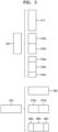
- FIG. 5 illustrates a method, performed by the image decoding apparatus 150, of determining a coding unit of a predetermined location from among an odd number of coding units, according to an embodiment.
- image decoding apparatus 150 may use information indicating locations of the odd number of coding units, to determine a coding unit at a center location from among the odd number of coding units. Referring to FIG. 5 , the image decoding apparatus 150 may determine an odd number of coding units 520a, 520b, and 520c by splitting the current coding unit 500. The image decoding apparatus 150 may determine a coding unit 520b at a center location by using information about locations of the odd number of coding units 520a, 520b, and 520c.
- the image decoding apparatus 150 may determine the coding unit 520b of the center location by determining the locations of the coding units 520a, 520b, and 520c based on information indicating locations of predetermined samples included in the coding units 520a, 520b, and 520c.
- the image decoding apparatus 150 may determine the coding unit 520b at the center location by determining the locations of the coding units 520a, 520b, and 520c based on information indicating locations of upper left samples 530a, 530b, and 530c of the coding units 520a, 520b, and 520c.
- the information indicating the locations of the upper left samples 530a, 530b, and 530c, which are included in the coding units 520a, 520b, and 520c, respectively, may include information about locations or coordinates of the coding units 520a, 520b, and 520c in a picture.
- the information indicating the locations of the upper left samples 530a, 530b, and 530c, which are included in the coding units 520a, 520b, and 520c, respectively may include information indicating widths or heights of the coding units 520a, 520b, and 520c included in the current coding unit 500, and the widths or heights may correspond to information indicating differences between the coordinates of the coding units 520a, 520b, and 520c in the picture.
- the image decoding apparatus 150 may determine the coding unit 520b at the center location by directly using the information about the locations or coordinates of the coding units 520a, 520b, and 520c in the picture, or by using the information about the widths or heights of the coding units, which correspond to the difference values between the coordinates.
- information indicating the location of the upper left sample 530a of the upper coding unit 520a may include coordinates (xa, ya)
- information indicating the location of the upper left sample 530b of the middle coding unit 520b may include coordinates (xb, yb)
- information indicating the location of the upper left sample 530c of the lower coding unit 520c may include coordinates (xc, yc).
- the image decoding apparatus 150 may determine the middle coding unit 520b by using the coordinates of the upper left samples 530a, 530b, and 530c which are included in the coding units 520a, 520b, and 520c, respectively.
- the coding unit 520b including the coordinates (xb, yb) of the sample 530b at a center location may be determined as a coding unit at a center location from among the coding units 520a, 520b, and 520c determined by splitting the current coding unit 500.
- the coordinates indicating the locations of the upper left samples 530a, 530b, and 530c may include coordinates indicating absolute locations in the picture, or may use coordinates (dxb, dyb) indicating a relative location of the upper left sample 530b of the middle coding unit 520b and coordinates (dxc, dyc) indicating a relative location of the upper left sample 530c of the lower coding unit 520c with reference to the location of the upper left sample 530a of the upper coding unit 520a.
- a method of determining a coding unit at a predetermined location by using coordinates of a sample included in the coding unit, as information indicating a location of the sample is not limited to the above-described method, and may include various arithmetic methods capable of using the coordinates of the sample.
- the image decoding apparatus 150 may split the current coding unit 500 into a plurality of coding units 520a, 520b, and 520c, and may select one of the coding units 520a, 520b, and 520c based on a predetermined criterion. For example, the image decoding apparatus 150 may select the coding unit 520b, which has a size different from that of the others, from among the coding units 520a, 520b, and 520c.
- the image decoding apparatus 150 may determine the width or height of each of the coding units 520a, 520b, and 520c by using the coordinates (xa, ya) that is the information indicating the location of the upper left sample 530a of the upper coding unit 520a, the coordinates (xb, yb) that is the information indicating the location of the upper left sample 530b of the middle coding unit 520b, and the coordinates (xc, yc) that is the information indicating the location of the upper left sample 530c of the lower coding unit 520c.
- the image decoding apparatus 150 may determine the respective sizes of the coding units 520a, 520b, and 520c by using the coordinates (xa, ya), (xb, yb), and (xc, yc) indicating the locations of the coding units 520a, 520b, and 520c.
- the image decoding apparatus 150 may determine the width of the upper coding unit 520a to be xb-xa and determine the height thereof to be yb-ya. According to an embodiment, the image decoding apparatus 150 may determine the width of the middle coding unit 520b to be xc-xb and determine the height thereof to be yc-yb. According to an embodiment, the image decoding apparatus 150 may determine the width or height of the lower coding unit 520c by using the width or height of the current coding unit 500, and the widths or heights of the upper and middle coding units 520a and 520b.
- the image decoding apparatus 150 may determine a coding unit, which has a size different from that of the others, based on the determined widths and heights of the coding units 520a to 520c. Referring to FIG. 5 , the image decoding apparatus 150 may determine the middle coding unit 520b, which has a size different from the size of the upper and lower coding units 520a and 520c, as the coding unit of the predetermined location.
- the above-described method, performed by the image decoding apparatus 150, of determining a coding unit having a size different from the size of the other coding units merely corresponds to an example of determining a coding unit at a predetermined location by using the sizes of coding units, which are determined based on coordinates of samples, and thus various methods of determining a coding unit at a predetermined location by comparing the sizes of coding units, which are determined based on coordinates of predetermined samples, may be used.
- locations of samples considered to determine locations of coding units are not limited to the above-described upper left locations, and information about arbitrary locations of samples included in the coding units may be used.
- the image decoding apparatus 150 may select a coding unit at a predetermined location from among an odd number of coding units determined by splitting the current coding unit, considering the shape of the current coding unit. For example, when the current coding unit has a non-square shape, a width of which is longer than a height, the image decoding apparatus 150 may determine the coding unit at the predetermined location in a horizontal direction. That is, the image decoding apparatus 150 may determine one of coding units at different locations in a horizontal direction and put a restriction on the coding unit. When the current coding unit has a non-square shape, a height of which is longer than a width, the image decoding apparatus 150 may determine the coding unit at the predetermined location in a vertical direction. That is, the image decoding apparatus 150 may determine one of coding units at different locations in a vertical direction and put a restriction on the coding unit.
- the image decoding apparatus 150 may use information indicating respective locations of an even number of coding units, to determine the coding unit at the predetermined location from among the even number of coding units.
- the image decoding apparatus 150 may determine an even number of coding units by splitting the current coding unit, and may determine the coding unit at the predetermined location by using the information about the locations of the even number of coding units.
- An operation related thereto may correspond to the operation of determining a coding unit at a predetermined location (e.g., a center location) from among an odd number of coding units, which has been described in detail above in relation to FIG. 5 , and thus detailed descriptions thereof are not provided here.
- predetermined information about a coding unit at a predetermined location may be used in a splitting operation to determine the coding unit at the predetermined location from among the plurality of coding units.
- the image decoding apparatus 150 may use at least one of block shape information and split shape information, which is stored in a sample included in a coding unit at a center location, in a splitting operation to determine the coding unit at the center location from among the plurality of coding units determined by splitting the current coding unit.
- the image decoding apparatus 150 may split the current coding unit 500 into a plurality of coding units 520a, 520b, and 520c based on at least one of the block shape information and the split shape information, and may determine the coding unit 520b at a center location from among the plurality of the coding units 520a, 520b, and 520c. Furthermore, the image decoding apparatus 150 may determine the coding unit 520b at the center location, in consideration of a location from which at least one of the block shape information and the split shape information is obtained.
- At least one of the block shape information and the split shape information of the current coding unit 500 may be obtained from the sample 540 at a center location of the current coding unit 500 and, when the current coding unit 500 is split into the plurality of coding units 520a, 520b, and 520c based on at least one of the block shape information and the split shape information, the coding unit 520b including the sample 540 may be determined as the coding unit at the center location.
- information used to determine the coding unit at the center location is not limited to at least one of the block shape information and the split shape information, and various types of information may be used to determine the coding unit at the center location.
- predetermined information for identifying the coding unit at the predetermined location may be obtained from a predetermined sample included in a coding unit to be determined.
- the image decoding apparatus 150 may use at least one of the block shape information and the split shape information, which is obtained from a sample at a predetermined location in the current coding unit 500 (e.g., a sample at a center location of the current coding unit 500) to determine a coding unit at a predetermined location from among the plurality of the coding units 520a, 520b, and 520c determined by splitting the current coding unit 500 (e.g., a coding unit at a center location from among a plurality of split coding units).
- the image decoding apparatus 150 may determine the sample at the predetermined location by considering a block shape of the current coding unit 500, determine the coding unit 520b including a sample, from which predetermined information (e.g., at least one of the block shape information and the split shape information) may be obtained, from among the plurality of coding units 520a, 520b, and 520c determined by splitting the current coding unit 500, and may put a predetermined restriction on the coding unit 520b.
- predetermined information e.g., at least one of the block shape information and the split shape information
- the image decoding apparatus 150 may determine the sample 540 at the center location of the current coding unit 500 as the sample from which the predetermined information may be obtained, and may put a predetermined restriction on the coding unit 520b including the sample 540, in a decoding operation.
- the location of the sample from which the predetermined information may be obtained is not limited to the above-described location, and may include arbitrary locations of samples included in the coding unit 520b to be determined for a restriction.
- the location of the sample from which the predetermined information may be obtained may be determined based on the shape of the current coding unit 500.
- the block shape information may indicate whether the current coding unit has a square or non-square shape, and the location of the sample from which the predetermined information may be obtained may be determined based on the shape.
- the image decoding apparatus 150 may determine a sample located on a boundary for splitting at least one of a width and height of the current coding unit in half, as the sample from which the predetermined information may be obtained, by using at least one of information about the width of the current coding unit and information about the height of the current coding unit.
- the image decoding apparatus 150 may determine one of samples adjacent to a boundary for splitting a long side of the current coding unit in half, as the sample from which the predetermined information may be obtained.
- the image decoding apparatus 150 may use at least one of the block shape information and the split shape information to determine a coding unit at a predetermined location from among the plurality of coding units.
- the image decoding apparatus 150 may obtain at least one of the block shape information and the split shape information from a sample at a predetermined location in a coding unit, and split the plurality of coding units, which are generated by splitting the current coding unit, by using at least one of the split shape information and the block shape information, which is obtained from the sample of the predetermined location in each of the plurality of coding units.
- a coding unit may be recursively split based on at least one of the block shape information and the split shape information, which is obtained from the sample at the predetermined location in each coding unit.
- the image decoding apparatus 150 may determine one or more coding units by splitting the current coding unit, and may determine an order of decoding the one or more coding units, based on a predetermined block (e.g., the current coding unit).
- FIG. 6 illustrates an order of processing a plurality of coding units when the image decoding apparatus 150 determines the plurality of coding units by splitting a current coding unit, according to an embodiment.
- the image decoding apparatus 150 may determine second coding units 610a and 610b by splitting a first coding unit 600 in a vertical direction, determine second coding units 630a and 630b by splitting the first coding unit 600 in a horizontal direction, or determine second coding units 650a to 650d by splitting the first coding unit 600 in vertical and horizontal directions, based on block shape information and split shape information.
- the image decoding apparatus 150 may determine to process the second coding units 610a and 610b, which are determined by splitting the first coding unit 600 in a vertical direction, in a horizontal direction order 610c.
- the image decoding apparatus 150 may determine to process the second coding units 630a and 630b, which are determined by splitting the first coding unit 600 in a horizontal direction, in a vertical direction order 630c.
- the image decoding apparatus 150 may determine to process the second coding units 650a to 650d, which are determined by splitting the first coding unit 600 in vertical and horizontal directions, in a predetermined order for processing coding units in a row and then processing coding units in a next row (e.g., in a raster scan order or Z-scan order 650e).
- the image decoding apparatus 150 may recursively split coding units.
- the image decoding apparatus 150 may determine the plurality of coding units 610a and 610b, 630a and 630b, or 650a to 650d by splitting the first coding unit 600, and recursively split each of the determined plurality of coding units 610b, 630a and 630b, or 650a to 650d.
- a splitting method of the plurality of coding units 610b, 630a and 630b, or 650a to 650d may correspond to a splitting method of the first coding unit 600.
- each of the plurality of coding units 610b, 630a and 630b, or 650a to 650d may be independently split into a plurality of coding units.
- the image decoding apparatus 150 may determine the second coding units 610a and 610b by splitting the first coding unit 600 in a vertical direction, and may determine to independently split or not to split each of the second coding units 610a and 610b.
- FIG. 7 illustrates a process, performed by the image decoding apparatus 150, of determining that a current coding unit is to be split into an odd number of coding units, when the coding units are not processable in a predetermined order, according to an embodiment.
- the image decoding apparatus 150 may determine whether the current coding unit is split into an odd number of coding units, based on obtained block shape information and split shape information. Referring to FIG. 7 , a square first coding unit 700 may be split into non-square second coding units 710a and 710b, and the second coding units 710a and 710b may be independently split into third coding units 720a and 720b, and 720c to 720e. According to an embodiment, the image decoding apparatus 150 may determine the plurality of third coding units 720a and 720b by splitting the left second coding unit 710a in a horizontal direction, and may split the right second coding unit 710b into the odd number of third coding units 720c to 720e.
- the image decoding apparatus 150 may determine whether any of the first coding unit 700, the second coding units 710a and 710b, and the third coding units 720a and 720b, and 720c to 720e are split into an odd number of coding units, based on at least one of the block shape information and the split shape information. For example, the right second coding unit 710b among the second coding units 710a and 710b may be split into an odd number of third coding units 720c, 720d, and 720e.
- a processing order of a plurality of coding units included in the first coding unit 700 may be a predetermined order (e.g., a Z-scan order 730), and the image decoding apparatus 150 may determine whether the third coding units 720c, 720d, and 720e, which are determined by splitting the right second coding unit 710b into an odd number of coding units, satisfy a condition for processing in the predetermined order.
- a predetermined order e.g., a Z-scan order 730
- the image decoding apparatus 150 may decide disconnection of a scan order, and determine that the right second coding unit 710b is split into an odd number of coding units, based on a result of the decision.
- a certain limit may be placed on a coding unit at a certain position among the odd number of coding units, and the limit or the position is as described above using various embodiments and thus a detailed description thereof will be omitted here.
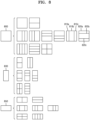
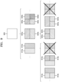
- FIG. 8 illustrates a process of determining at least one coding unit by splitting a first coding unit 800, the process being performed by the image decoding apparatus 150, according to an embodiment.
- the image decoding apparatus 150 may split the first coding unit 800, based on at least one of block shape information or split type information, which is obtained by the receiver 160.
- the square first coding unit 800 may be split into four square coding units or into a plurality of non-square coding units. For example, referring to FIG.
- the image decoding apparatus 150 may split the first coding unit 800 into a plurality of non-square coding units.
- the image decoding apparatus 150 may split the square first coding unit 800 into an odd number of coding units, e.g., second coding units 810a, 810b, and 810c determined by splitting the square first coding unit 8600 in the vertical direction or second coding units 820a, 820b, and 820c determined by splitting the square first coding unit 800 in the horizontal direction.
- odd number of coding units e.g., second coding units 810a, 810b, and 810c determined by splitting the square first coding unit 8600 in the vertical direction or second coding units 820a, 820b, and 820c determined by splitting the square first coding unit 800 in the horizontal direction.
- the image decoding apparatus 150 may determine whether the second coding units 810a, 810b, 810c, 820a, 820b, and 820c included in the first coding unit 800 satisfy a condition for processing in a certain order, and the condition relates to whether at least one of a width or height of the first coding unit 800 is split in half by boundaries of the second coding units 810a, 810b, 810c, 820a, 820b, and 820c. Referring to FIG.
- the image decoding apparatus 150 may determine disconnection of a scan order and determine that the first coding unit 800 is to be split into an odd number of coding units, based on a result of the determination.
- a certain limit may be placed on a coding unit at a certain position among the odd number of coding units, and the limit or the position is as described above using various embodiments and thus a detailed description thereof will be omitted here.
- the image decoding apparatus 150 may determine various-shaped coding units by splitting a first coding unit.
- the image decoding apparatus 150 may split the square first coding unit 800 and a non-square first coding unit 830 or 850 into various-shaped coding units.
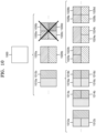
- FIG. 9 illustrates a case in which when a non-square second coding unit determined by splitting a first coding unit 900 by the image decoding apparatus 150 satisfies a certain condition, a shape into which the second coding unit may be split is limited, according to an embodiment.
- the image decoding apparatus 150 may determine to split the square first coding unit 900 into non-square second coding units 910a, 910b, 920a, and 920b, based on at least one of block shape information and split shape information, which is obtained by the receiver 160.
- the second coding units 910a and 910b or 920a and 920b may be independently split.
- the image decoding apparatus 150 may determine to split or not to split the second coding units 910a, 910b, 920a, and 920b into a plurality of coding units, based on at least one of the block shape information and the split shape information of each of the second coding units 910a, 910b, 920a, and 920b.
- the image decoding apparatus 150 may determine third coding units 912a and 912b by splitting the non-square left second coding unit 910a, which is determined by splitting the first coding unit 900 in a vertical direction, in a horizontal direction. However, when the left second coding unit 910a is split in a horizontal direction, the image decoding apparatus 150 may restrict the right second coding unit 910b to not be split in a horizontal direction in which the left second coding unit 910a is split.
- the image decoding apparatus 150 may determine third coding units 922a and 922b or 924a and 924b by splitting the non-square second coding unit 920a or 920b, which is determined by splitting the first coding unit 900 in a horizontal direction, in a vertical direction.
- a second coding unit e.g., the upper second coding unit 920a
- the image decoding apparatus 150 may restrict the other second coding unit (e.g., the lower second coding unit 920b) to not be split in a vertical direction in which the upper second coding unit 920a is split.
- FIG. 10 illustrates a process, performed by the image decoding apparatus 150, of splitting a square coding unit when split shape information indicates that the square coding unit is not to be split into four square coding units, according to an embodiment.
- the image decoding apparatus 150 may determine second coding units 1010a, 1010b, 1020a, 1020b, etc. by splitting a first coding unit 1000, based on at least one of block shape information and split shape information.
- the split shape information may include information about various methods of splitting a coding unit but, the information about various splitting methods may not include information for splitting a coding unit into four square coding units. According to such split shape information, the image decoding apparatus 150 may not split the square first coding unit 1000 into four square second coding units 1030a, 1030b, 1030c, and 1030d.
- the image decoding apparatus 150 may determine the non-square second coding units 1010a and 1010b or 1020a and 1020b, etc., based on the split shape information.
- the image decoding apparatus 150 may independently split the non-square second coding units 1010a and 1010b or 1020a and 1020b, etc.
- Each of the second coding units 1010a, 1010b, 1020a, 1020b, etc. may be recursively split in a predetermined order, and this splitting method may correspond to a method of splitting the first coding unit 1000, based on at least one of the block shape information and the split shape information.
- the image decoding apparatus 150 may determine square third coding units 1012a and 1012b by splitting the left second coding unit 1010a in a horizontal direction, and may determine square third coding units 1014a and 1014b by splitting the right second coding unit 1010b in a horizontal direction. Furthermore, the image decoding apparatus 150 may determine square third coding units 1016a, 1016b, 1016c, and 1016d by splitting both of the left and right second coding units 1010a and 1010b in a horizontal direction. In this case, coding units having the same shape as the four square second coding units 1030a, 1030b, 1030c, and 1030d split from the first coding unit 1000 may be determined.
- the image decoding apparatus 160 may determine square third coding units 1022a and 1022b by splitting the upper second coding unit 1020a in a vertical direction, and may determine square third coding units 1024a and 1024b by splitting the lower second coding unit 1020b in a vertical direction. Furthermore, the image decoding apparatus 150 may determine square third coding units 1026a, 1026b, 1026c, and 1026d by splitting both of the upper and lower second coding units 1020a and 1020b in a vertical direction. In this case, coding units having the same shape as the four square second coding units 1030a, 1030b, 1030c, and 1030d split from the first coding unit 1000 may be determined.
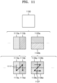
- FIG. 11 illustrates that a processing order between a plurality of coding units may be changed depending on a process of splitting a coding unit, according to an embodiment.
- the image decoding apparatus 150 may split a first coding unit 1100, based on block shape information and split shape information.
- the image decoding apparatus 150 may determine second coding units 1110a, 1110b, 1120a, 1120b by splitting the first coding unit 1100.
- the non-square second coding units 1110a, 1110b, 1120a, and 1120b determined by splitting the first coding unit 1100 in only a horizontal direction or vertical direction may be independently split based on the block shape information and the split shape information of each coding unit.
- the image decoding apparatus 150 may determine third coding units 1116a, 1116b, 1116c, and 1116d by splitting the second coding units 1110a and 1110b, which are generated by splitting the first coding unit 1100 in a vertical direction, in a horizontal direction, and may determine third coding units 1126a, 1126b, 1126c, and 1126d by splitting the second coding units 1120a and 1120b, which are generated by splitting the first coding unit 1100 in a horizontal direction, in a vertical direction.
- An operation of splitting the second coding units 1110a and 1110b or 1120a and 1120b has been described above in relation to FIG. 9 , and thus detailed descriptions thereof will not be provided herein.
- the image decoding apparatus 150 may determine the third coding units 1116a, 1116b, 1116c, and 1116d by splitting the second coding units 1110a and 1110b generated by splitting the first coding unit 1100 in a vertical direction, in a horizontal direction, and may process the third coding units 1116a, 1116b, 1116c, and 1116d in a processing order 1117 for initially processing the third coding units 1116a and 1116c, which are included in the left second coding unit 1110a, in a vertical direction and then processing the third coding unit 1116b and 1116d, which are included in the right second coding unit 1110b, in a vertical direction.
- the image decoding apparatus 150 may determine the third coding units 1126a, 1126b, 1126c, and 1126d by splitting the second coding units 1120a and 1120b generated by splitting the first coding unit 1100 in a horizontal direction, in a vertical direction, and may process the third coding units 1126a, 1126b, 1126c, and 1126d in a processing order 1127 for initially processing the third coding units 1126a and 1126b, which are included in the upper second coding unit 1120a, in a horizontal direction and then processing the third coding unit 1126c and 1126d, which are included in the lower second coding unit 1120b, in a horizontal direction.
- the square third coding units 1116a, 1116b, 1116c, and 1116d, and 1126a, 1126b, 1126c, and 1126d may be determined by splitting the second coding units 1110a and 1110b, and 1120a and 1120b, respectively.
- the second coding units 1110a and 1110b are determined by splitting the first coding unit 1100 in a vertical direction differently from the second coding units 1120a and 1120b which are determined by splitting the first coding unit 1100 in a horizontal direction
- the third coding units 1116a, 1116b, 1116c, and 1116d, and 1126a, 1126b, 1126c, and 1126d split therefrom eventually show same-shaped coding units split from the first coding unit 1100.
- the image decoding apparatus 150 may process a plurality of coding units in different orders even when the coding units are eventually determined to be the same shape.
- FIG. 12 illustrates a process of determining a depth of a coding unit as a shape and size of the coding unit change, when the coding unit is recursively split such that a plurality of coding units are determined, according to an embodiment.
- the image decoding apparatus 150 may determine whether to use a specific splitting method, based on PID values for identifying a plurality of coding units determined by splitting a current coding unit. Referring to FIG. 13 , the image decoding apparatus 150 may determine an even number of coding units 1312a and 1312b or an odd number of coding units 1314a, 1314b, and 1314c by splitting the first coding unit 1310 having a rectangular shape, a height of which is longer than a width. The image decoding apparatus 150 may use PIDs to identify respective coding units. According to an embodiment, the PID may be obtained from a sample of a predetermined location of each coding unit (e.g., an upper left sample).
- the image decoding apparatus 150 may compare PIDs of an odd number of split coding units to determine a coding unit at a center location from among the coding units.
- the image decoding apparatus 150 may determine the coding unit 1314b having a PID corresponding to a middle value among the PIDs of the coding units, as the coding unit at the center location from among the coding units determined by splitting the first coding unit 1310.
- the image decoding apparatus 150 may determine PIDs for distinguishing split coding units, based on a size ratio between the coding units when the split coding units do not have equal sizes. Referring to FIG.
- the coding unit 1314b generated by splitting the first coding unit 1310 may have a width equal to that of the other coding units 1314a and 1314c and a height which is two times that of the other coding units 1314a and 1314c.
- the PID of the coding unit 1314b at the center location is 1, the PID of the coding unit 1314c located next to the coding unit 1314b may be increased by 2 and thus may be 3.
- the image decoding apparatus 150 may determine that a coding unit is split into a plurality of coding units including a coding unit having a size different from that of the other coding units.
- the image decoding apparatus 150 may split a current coding unit in such a manner that a coding unit of a predetermined location among an odd number of coding units (e.g., a coding unit of a centre location) has a size different from that of the other coding units.
- the image decoding apparatus 150 may determine the coding unit of the centre location, which has a different size, by using PIDs of the coding units.
- the PIDs and the size or location of the coding unit of the predetermined location are not limited to the above-described examples, and various PIDs and various locations and sizes of coding units may be used.
- the image decoding apparatus 150 may use a predetermined data unit where a coding unit starts to be recursively split.
- a predetermined data unit may be defined as a data unit where a coding unit starts to be recursively split by using at least one of block shape information and split shape information. That is, the predetermined data unit may correspond to a coding unit of an uppermost depth, which is used to determine a plurality of coding units split from a current picture.
- the predetermined data unit is referred to as a reference data unit.
- the reference data unit may have a predetermined size and a predetermined size shape.
- the reference data unit may include M ⁇ N samples.
- M and N may be equal to each other, and may be integers expressed as powers of 2. That is, the reference data unit may have a square or non-square shape, and may be split into an integer number of coding units.
- the image decoding apparatus 150 may split the current picture into a plurality of reference data units. According to an embodiment, the image decoding apparatus 150 may split the plurality of reference data units, which are split from the current picture, by using splitting information about each reference data unit. The operation of splitting the reference data unit may correspond to a splitting operation using a quadtree structure.
- the image decoding apparatus 150 may previously determine the minimum size allowed for the reference data units included in the current picture. Accordingly, the image decoding apparatus 150 may determine various reference data units having sizes equal to or greater than the minimum size, and may determine one or more coding units by using the block shape information and the split shape information with reference to the determined reference data unit.
- the image decoding apparatus 150 may use a square reference coding unit 1400 or a non-square reference coding unit 1402.
- the shape and size of reference coding units may be determined based on various data units capable of including one or more reference coding units (e.g., sequences, pictures, slices, slice segments, largest coding units, or the like).
- the receiver 160 of the image decoding apparatus 150 may obtain, from a bitstream, at least one of reference coding unit shape information and reference coding unit size information with respect to each of the various data units.
- An operation of splitting the square reference coding unit 1400 into one or more coding units has been described above in relation to the operation of splitting the current coding unit 200 of FIG. 2
- an operation of splitting the non-square reference coding unit 1402 into one or more coding units has been described above in relation to the operation of splitting the current coding unit 300 or 350 of FIG. 3 .
- detailed descriptions thereof will not be provided herein.
- the image decoding apparatus 150 may use a PID for identifying the size and shape of reference coding units, to determine the size and shape of reference coding units according to some data units previously determined based on a predetermined condition. That is, the receiver 160 may obtain, from the bitstream, only the PID for identifying the size and shape of reference coding units with respect to each slice, slice segment, or largest coding unit which is a data unit satisfying a predetermined condition (e.g., a data unit having a size equal to or smaller than a slice) among the various data units (e.g., sequences, pictures, slices, slice segments, largest coding units, or the like).
- a predetermined condition e.g., a data unit having a size equal to or smaller than a slice
- the image decoding apparatus 150 may determine at least one of the size and shape of reference coding units included in a data unit serving as a unit for obtaining the PID, by selecting the previously determined at least one of the size and shape of reference coding units based on the PID.
- the image decoding apparatus 150 may use one or more reference coding units included in a largest coding unit. That is, a largest coding unit split from a picture may include one or more reference coding units, and coding units may be determined by recursively splitting each reference coding unit. According to an embodiment, at least one of a width and height of the largest coding unit may be integer times at least one of the width and height of the reference coding units. According to an embodiment, the size of reference coding units may be obtained by splitting the largest coding unit n times based on a quadtree structure.
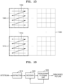
- FIG. 15 illustrates a processing block serving as a criterion for determining a determination order of reference coding units included in a picture 1500, according to an embodiment.
- the image decoding apparatus 150 may obtain processing block size information and may determine the size of one or more processing blocks included in the picture.
- the image decoding apparatus 150 may obtain the processing block size information from a bitstream and may determine the size of one or more processing blocks included in the picture.
- the size of processing blocks may be a predetermined size of data units, which is indicated by the processing block size information.
- the receiver 160 of the image decoding apparatus 150 may obtain the processing block size information from the bitstream according to each specific data unit.
- the processing block size information may be obtained from the bitstream in a data unit such as an image, sequence, picture, slice, or slice segment. That is, the receiver 160 may obtain the processing block size information from the bitstream according to each of the various data units, and the image decoding apparatus 150 may determine the size of one or more processing blocks, which are split from the picture, by using the obtained processing block size information.
- the size of the processing blocks may be integer times that of the reference coding units.
- Whether to apply a deblocking filter is determined in consideration of a block size, a method of encoding a block, and pixel values of the pixels at the block boundary.
- a deblocking filter to be used for the block boundary may be selected according to a degree of blocking artifact.
- a method of applying a deblocking filter to blocks of a decoded picture will be described below.
- the extractor 1610, the decoder 1620, and the deblocking filtering unit 1630 are illustrated as components located in one device but devices functioning as the extractor 1610, the decoder 1620, and the deblocking filtering unit 1630 are not necessarily physically contiguous. Therefore, according to one embodiment, the extractor 1610, the decoder 1620, and the deblocking filtering unit 1630 may be dispersed.
- the deblocking filtering unit 1630 may determine whether to apply a deblocking filter to the neighboring pixels according to the difference in size between a motion vector used for prediction of the current block and a motion vector used for prediction of the neighboring block.
- the deblocking filtering unit 1630 may determine whether to apply a deblocking filter to the neighboring pixels according to whether a reference picture used for prediction of the current block and a reference picture used for prediction of the neighboring block are the same.
- the current block and the neighboring block are predicted using the same reference picture and the same motion vector, pixels at the boundary of the two blocks are likely to be continuous.
- the deblocking filtering unit 1630 may determine to apply a deblocking filter to the pixels in the first to fourth columns when integer values of motion vectors of the square block 1890 including the p0,0 pixel in the first column and the square block 1895 including the q0,0 pixel in the first column are different or when the reference pixels are different.
- the deblocking filtering unit 1630 may determine whether to apply a deblocking filter to the neighboring pixels according to whether there is a non-zero transform coefficient in two blocks including pixels at a block boundary.
- the transform coefficient refer to a coefficient included in a transform block generated by frequency transforming a difference block representing the difference between a predicted block and an original block.
- the deblocking filtering unit 1630 may apply a deblocking filter to improve continuity between the pixels because there is a high possibility of an error in prediction of the pixels.
- the deblocking filtering unit 1630 may identify whether there is at least one non-zero transform coefficient among transform coefficients of the block 1810 including the p0,0 pixels in the first row and the block 1820 including the q0,0 pixels.
- the deblocking filtering unit 1630 may apply a deblocking filter to pixels of the 4x4 blocks 1840 and 1845 when at least one non-zero transform coefficient is found.
- FIG. 18A the deblocking filtering unit 1630 may identify whether there is at least one non-zero transform coefficient among transform coefficients of the block 1810 including the p0,0 pixels in the first row and the block 1820 including the q0,0 pixels.
- the deblocking filtering unit 1630 may apply a deblocking filter to pixels of the 4x4 blocks 1840 and 1845 when at least one non-zero transform coefficient is found.
- FIG. 18A the deblocking filtering unit 1630 may identify whether there is at least one non-zero transform coefficient among transform coefficients of the block 1810 including the p
- the deblocking filtering unit 1630 may apply a deblocking filter to pixels of the 4x4 blocks 1890 and 1895.
- the deblocking filtering unit 1630 may apply a deblocking filter to the neighboring pixels. In addition, the deblocking filtering unit 1630 may apply the deblocking filter to the neighboring pixels according to the sum of absolute values of transform coefficients of the neighboring pixels.
- the deblocking filtering unit 1630 may compare a threshold determined by a quantization parameter of a current block and a quantization parameter of a neighboring block with difference information between neighboring samples to determine whether to apply the deblocking filter to the neighboring pixels.
- the deblocking filtering unit 1630 may calculate changing amount d of a pixel value in a block and determine whether to apply the deblocking filter to neighboring pixels according to the changing amount d. In addition, the deblocking filtering unit 1630 may compare the changing amount d with a threshold ⁇ determined from an average value of the quantization parameter of the current block and the quantization parameter of the neighboring block. Because blocking artifact increases as a quantization parameter increases, the threshold ⁇ increases as the average value of the quantization parameters increases. Therefore, whether the changing amount d is small is determined relative to the average value of the quantization parameters.
- Equation 1 represents the changing amount d for determining whether to apply the deblocking filter to neighboring pixels at a vertical boundary.
- d abs(p2,0 - 2*p1,0 + p0,0) + abs(p2,3 - 2*p1,3 + p0,3) + abs(q2,0 - 2*q1,0 + q0,0) + abs(q2,3 - 2*q1,3 + q0,3)
- abs(X) represents an absolute value of X
- p0,0, p1,0, p2,0, p0,3, p1,3, p2,3, q0,0, q1,0, q2,0, q0,3, q1,3, and q2,3 represent pixel values of pixels illustrated in FIG. 18A .
- the sum of abs(p2,0 - 2*p1,0 + p0,0) and abs(q2,0 - 2*q1,0 + q0,0) represents the changing amount in the first row
- the sum of abs(p2,3 - 2*p1,3 + p0,3) and abs(q2,3 - 2*q1,3 + q0,3) represents the changing amount in the fourth row.
- the changing amount d for determining whether to perform deblocking filtering at the vertical boundary is calculated by adding the changing amount in the first row and the changing amount in the fourth row.
- Equation 2 represents the changing amount d for determining whether to apply the deblocking filter to neighboring pixels at a horizontal boundary.
- d abs(p0,2 - 2*p0,1 + p0,0) + abs(p3,2 - 2*p3,1 + p3,0) + abs(q0,2 - 2*q0,1 + q0,0) + abs(q3,2 - 2*q3,1 + q3,0)
- abs(X) represents an absolute value of X
- p0,0, p0,1, p0,2, p3,0, p3,1, p3,2, q0,0, q0,1, q0,2, q3,0, q3,1, and q3,2 represent pixel values of pixels illustrated in FIG. 18B .
- the sum of abs(p0,2 - 2*p0,1 + p0,0) and abs(p3,2 - 2*p3,1 + p3,0) represents the changing amount in the first column
- the sum of abs(p3,2 - 2*p3,1 + p3,0) and abs(q3,2 - 2*q3,1 + q3,0) represents the changing amount in the fourth column.
- the changing amount d for determining whether to perform deblocking filtering at the horizontal boundary is calculated by adding the changing amount in the first column and the changing amount in the fourth column.
- the values used in Equations 1 and 2 may be changed for optimization.
- the deblocking filtering unit 1630 may apply a deblocking filter to neighboring pixels when the changing amount d calculated from Equation 1 or 2 is less than the threshold ⁇ . Conversely, a deblocking filter may not be applied to the neighboring pixels when the changing amount d calculated from Equation 1 or 2 is greater than the threshold ⁇ .
- the deblocking filtering unit 1630 may determine whether to apply a deblocking filter to neighboring pixels in consideration of a plurality of conditions disclosed in this specification. When at least one condition causing pixel discontinuity to occur at a block boundary is found from encoding information of the neighboring pixels, the deblocking filtering unit 1630 may apply a deblocking filter to the neighboring pixels. However, when at least one condition causing pixel discontinuity to occur at a block boundary is not found from the encoding information of the neighboring pixels, the deblocking filtering unit 1630 does not apply a deblocking filter to the neighboring pixels.
- the deblocking filtering unit 1630 may select a deblocking filter to be applied to the neighboring pixels from among a plurality of deblocking filters according to pixel values of the neighboring pixels.
- the deblocking filtering unit 1630 may select a deblocking filter for each row with respect to a vertical boundary.
- the deblocking filtering unit 1630 may select a deblocking filter for each column with respect to a horizontal boundary.
- the plurality of deblocking filters are classified according to a filtering area to which a deblocking filter is applied. The stronger a deblocking filter, the wider a filtering area, and the weaker the deblocking filter, the narrower the filtering area.
- the plurality of deblocking filters may include a first deblocking filter, a second deblocking filter, and a third deblocking filter.
- the first deblocking filter is a filter with a narrowest filtering area.
- the second deblocking filter has a larger filtering area than that of the first deblocking filter, and the third deblocking filter has a larger filtering area than those of the first deblocking filter and the second deblocking filter. Therefore, the third deblocking filter is a strongest deblocking filter among the first to third deblocking filters.
- the plurality of deblocking filters may additionally include a deblocking filter stronger than the third deblocking filter.
- the deblocking filtering unit 1630 may select a deblocking filter to be applied to neighboring pixels according to the size of the current block or the size of a neighboring block. For a large block, a range of neighboring samples to which deblocking filtering is applied may be increased and thus a stronger deblocking filter may be applied. For example, in the case of an 8x8 block, only pixels within a 4-pixel unit from a boundary of the 8x8 block may be targets to be deblocking-filtered. For example, in the case of a 16x16 block, pixels within an 8-pixel unit from a boundary of the 16x16 block may be also targets to be deblocking-filtered. Therefore, a stronger deblocking filter may be set to be used for large blocks.
- the deblocking filtering unit 1630 may select a deblocking filter by using the difference information in determining deblocking filter strength as the difference information is used in determining as to whether a deblocking filter is to be applied as described above. In addition, the deblocking filtering unit 1630 may compare the difference information with a threshold determined by a quantization parameter of a current block and a quantization parameter of a neighboring block to select a deblocking filter to be applied to neighboring pixels. Equations 3 to 5 used to determine difference information will be described based on FIGS. 19A and 19B below.
- Equations 3 to 5 below may be considered to select a deblocking filter for neighboring pixels at a vertical boundary.
- Equations 3 to 5 p0, p1, p2, p3, q0, q1, q2, and q3 represent pixel values of pixels located in the same row or column.
- p0, p1, p2, p3, q0, q1, q2, and q3 represent pixel values of pixels in the same row.
- p0, p1, p2, p3, q0, q1, q2, and q3 represent pixel values of pixels located in the same column.
- ⁇ /8 and tc represent thresholds determined from an average value of the quantization parameter of the current block and the quantization parameter of the neighboring block.
- the threshold ⁇ /8 is a value obtained by dividing a threshold ⁇ , which is used to determine whether to apply a deblocking filter to neighboring pixels, by 8.
- the thresholds ⁇ and ⁇ /8 are thresholds for the difference between pixels in a block
- the threshold tc is a threshold for the difference between pixels at a boundary of the block.
- Equation 6 represent pixel values of pixels located in the same row or column.
- p0, p7, q0, and q7 represent pixel values of pixels located in the same row.
- FIG. 19B p0, p7, q0, and q7 represent pixel values of pixels located in the same column.
- the deblocking filtering unit 1630 may apply the selected deblocking filter to pixels adjacent to a boundary.
- the first deblocking filter may be applied only to pixels within a 1-pixel unit or a 2-pixel unit from the boundary of the current block.
- the first deblocking filter is applied to the pixels within the 1-pixel unit
- the first deblocking filter is applied to the pixel values p0 and q0.
- the first deblocking filter may be applied to the pixel values p0, p1, q0, and q1.
- a range of target pixels to which the first deblocking filter is applied may be set to be greater than that in the above embodiment.
- the third deblocking filter may be applied only to pixels within a certain pixel unit among a 5-pixel unit to an 8-pixel unit from the boundary of the current block. For example, when the third deblocking filter is applied to pixels within the 7-pixel unit, the third deblocking filter may be applied to the pixel values p0, p1, p2, p3, p4, p5, p6, q0, q1, q2, q3, q4, q5, and q6.
- Target pixel to which the third deblocking filter is applied may be set differently from that in the above embodiment.
- the first deblocking filter may be a 4-tap filter.
- the first deblocking filter may be a 4-tap filter using the pixel values p0, p1, q0, and q1.
- the second deblocking filter may be a 4-tap filter or a 5-tap filter.
- the second deblocking filter may be a 4-tap filter using four pixels or a 5-tap filter using five pixels among the pixel values p0, p1, p2, p3, q0, q1, q2, and q3.
- the third deblocking filter may be a 9-tap filter, a 10-tap filter or an 11-tap filter.
- the first deblocking filter, the second deblocking filter, and the third deblocking filter are set differently according to the positions of pixels to be filtered.
- the third deblocking filter applied to the pixel value p0 may be a 5-tap filter.
- the third deblocking filter applied to the pixel value p2 may be a 4-tap filter.
- filter coefficients of the first deblocking filter, the second deblocking filter, and the third deblocking filter are set differently according to the positions of pixels to be filtered.
- FIG. 20 is a block diagram illustrating a method of determining whether to apply deblocking filtering to pixels adjacent to a block boundary.
- the deblocking filtering unit 1630 determines whether the changing amount d calculated by Equation 1 or 2 above is greater than a threshold ⁇ .
- the deblocking filtering unit 1630 does not perform deblocking filtering on the pixels in the pixel area determined by four rows or four columns.
- the deblocking filtering unit 1630 selects a deblocking filter to be applied to the pixels in the pixel region from a deblocking filter group.
- the deblocking filtering unit 1630 may determine whether to use the first deblocking filter according to the conditions of Equations 3 to 5 above. In detail, when any of the conditions of Equations 3 to 5 is not satisfied, the deblocking filtering unit 1630 selects the first deblocking filter. Conversely, in operation 2040, when all the conditions of Equations 3 to 5 are satisfied, the deblocking filtering unit 1630 may select one of a second deblocking filter and a third deblocking filter.
Landscapes
- Engineering & Computer Science (AREA)
- Multimedia (AREA)
- Signal Processing (AREA)
- Physics & Mathematics (AREA)
- Discrete Mathematics (AREA)
- General Physics & Mathematics (AREA)
- Compression Or Coding Systems Of Tv Signals (AREA)
Applications Claiming Priority (3)
| Application Number | Priority Date | Filing Date | Title |
|---|---|---|---|
| US201862614988P | 2018-01-08 | 2018-01-08 | |
| EP18898883.6A EP3739887A4 (de) | 2018-01-08 | 2018-03-29 | Codierungsverfahren und vorrichtung dafür sowie decodierungsverfahren und vorrichtung dafür |
| PCT/KR2018/003742 WO2019135446A1 (ko) | 2018-01-08 | 2018-03-29 | 부호화 방법 및 그 장치, 복호화 방법 및 그 장치 |
Related Parent Applications (1)
| Application Number | Title | Priority Date | Filing Date |
|---|---|---|---|
| EP18898883.6A Division EP3739887A4 (de) | 2018-01-08 | 2018-03-29 | Codierungsverfahren und vorrichtung dafür sowie decodierungsverfahren und vorrichtung dafür |
Publications (2)
| Publication Number | Publication Date |
|---|---|
| EP4580182A2 true EP4580182A2 (de) | 2025-07-02 |
| EP4580182A3 EP4580182A3 (de) | 2025-08-06 |
Family
ID=67144147
Family Applications (2)
| Application Number | Title | Priority Date | Filing Date |
|---|---|---|---|
| EP25176766.1A Pending EP4580182A3 (de) | 2018-01-08 | 2018-03-29 | Codierungsverfahren und vorrichtung dafür sowie decodierungsverfahren und vorrichtung dafür |
| EP18898883.6A Ceased EP3739887A4 (de) | 2018-01-08 | 2018-03-29 | Codierungsverfahren und vorrichtung dafür sowie decodierungsverfahren und vorrichtung dafür |
Family Applications After (1)
| Application Number | Title | Priority Date | Filing Date |
|---|---|---|---|
| EP18898883.6A Ceased EP3739887A4 (de) | 2018-01-08 | 2018-03-29 | Codierungsverfahren und vorrichtung dafür sowie decodierungsverfahren und vorrichtung dafür |
Country Status (5)
| Country | Link |
|---|---|
| US (5) | US11477446B2 (de) |
| EP (2) | EP4580182A3 (de) |
| KR (6) | KR102496622B1 (de) |
| CN (6) | CN117956195A (de) |
| WO (1) | WO2019135446A1 (de) |
Families Citing this family (3)
| Publication number | Priority date | Publication date | Assignee | Title |
|---|---|---|---|---|
| US10750171B2 (en) * | 2018-06-25 | 2020-08-18 | Google Llc | Deblocking filtering |
| WO2020228662A1 (en) | 2019-05-11 | 2020-11-19 | Beijing Bytedance Network Technology Co., Ltd. | Boundary strength determination for deblocking filters in video processing |
| CN117176969A (zh) * | 2019-05-11 | 2023-12-05 | 抖音视界有限公司 | 用于视频编解码的去方块滤波器 |
Family Cites Families (34)
| Publication number | Priority date | Publication date | Assignee | Title |
|---|---|---|---|---|
| US5337088A (en) | 1991-04-18 | 1994-08-09 | Matsushita Electric Industrial Co. Ltd. | Method of correcting an image signal decoded in block units |
| NO322722B1 (no) * | 2004-10-13 | 2006-12-04 | Tandberg Telecom As | Fremgangsmate for videokoding gjennom reduksjon av blokkartefakter |
| KR100711725B1 (ko) * | 2005-11-16 | 2007-04-25 | 엘지전자 주식회사 | 영상전화기의 디블록킹 필터링 방법 |
| US10123050B2 (en) * | 2008-07-11 | 2018-11-06 | Qualcomm Incorporated | Filtering video data using a plurality of filters |
| TWI386068B (zh) * | 2008-10-22 | 2013-02-11 | Nippon Telegraph & Telephone | 解塊處理方法、解塊處理裝置、解塊處理程式及記錄該程式之可由電腦讀取之記錄媒體 |
| US8761538B2 (en) * | 2008-12-10 | 2014-06-24 | Nvidia Corporation | Measurement-based and scalable deblock filtering of image data |
| TWI389577B (zh) * | 2009-12-31 | 2013-03-11 | Via Tech Inc | 視訊解碼解塊之裝置與方法 |
| CA3007527C (en) * | 2010-04-13 | 2020-06-23 | Samsung Electronics Co., Ltd. | Video encoding method and video encoding apparatus and video decoding method and video decoding apparatus, which perform deblocking filtering based on tree-structure encoding units |
| KR20110125153A (ko) * | 2010-05-12 | 2011-11-18 | 에스케이 텔레콤주식회사 | 영상의 필터링 방법 및 장치와 그를 이용한 부호화/복호화를 위한 방법 및 장치 |
| KR101826353B1 (ko) * | 2010-07-20 | 2018-02-09 | 에스케이텔레콤 주식회사 | 디블록킹 필터링 방법 및 장치 및 이를 이용한 부호화 및 복호화 방법과 장치 |
| CN105227958B (zh) * | 2010-07-20 | 2019-06-25 | Sk电信有限公司 | 用于解码视频信号的解码装置 |
| JP2012044535A (ja) * | 2010-08-20 | 2012-03-01 | Toshiba Corp | 動画像符号化装置及び動画像符号化方法 |
| US9819966B2 (en) * | 2010-09-01 | 2017-11-14 | Qualcomm Incorporated | Filter description signaling for multi-filter adaptive filtering |
| WO2012044074A2 (ko) * | 2010-09-28 | 2012-04-05 | 삼성전자 주식회사 | 적응적 필터링 방법 및 장치 |
| KR101772046B1 (ko) * | 2010-11-04 | 2017-08-29 | 에스케이텔레콤 주식회사 | 예측모드에 따라 필터링된 화소값으로 인트라예측을 수행하는 영상 부호화/복호화 방법 및 장치 |
| WO2012096614A2 (en) * | 2011-01-14 | 2012-07-19 | Telefonaktiebolaget L M Ericsson (Publ) | A method for filter control and a filtering control device |
| KR101584420B1 (ko) * | 2011-03-01 | 2016-01-22 | 텔레폰악티에볼라겟엘엠에릭슨(펍) | 디블록킹 필터링 제어 |
| CN107295341B (zh) * | 2011-07-22 | 2020-02-28 | Sk电信有限公司 | 视频编码方法 |
| EP3306921B1 (de) * | 2011-09-09 | 2020-11-04 | Sun Patent Trust | Niedrigkomplexe blockierungsfilterentscheidungen |
| US9161046B2 (en) * | 2011-10-25 | 2015-10-13 | Qualcomm Incorporated | Determining quantization parameters for deblocking filtering for video coding |
| DK2775711T3 (da) * | 2011-11-04 | 2020-04-06 | Lg Electronics Inc | Fremgangsmåde og apparat til at indkode/afkode billedeinformation |
| US9906790B2 (en) | 2014-03-14 | 2018-02-27 | Qualcomm Incorporated | Deblock filtering using pixel distance |
| CN119383364A (zh) | 2015-06-11 | 2025-01-28 | 杜比实验室特许公司 | 使用自适应去块滤波编码和解码图像的方法及介质 |
| US10304178B2 (en) * | 2015-09-18 | 2019-05-28 | Taiwan Semiconductor Manfacturing Company, Ltd. | Method and system for diagnosing a semiconductor wafer |
| WO2017054194A1 (en) * | 2015-09-30 | 2017-04-06 | Realnetworks, Inc. | Layered deblocking filtering in video processing systems and methods |
| JP6620354B2 (ja) | 2015-09-30 | 2019-12-18 | Kddi株式会社 | 動画像の処理装置、処理方法及びコンピュータ可読記憶媒体 |
| KR102445668B1 (ko) * | 2016-06-01 | 2022-09-21 | 삼성전자주식회사 | 부호화 순서 부호화 방법 및 그 장치, 복호화 방법 및 그 장치 |
| US10880548B2 (en) | 2016-06-01 | 2020-12-29 | Samsung Electronics Co., Ltd. | Methods and apparatuses for encoding and decoding video according to coding order |
| CN109479131B (zh) * | 2016-06-24 | 2023-09-01 | 世宗大学校产学协力团 | 视频信号处理方法及装置 |
| CN118869984A (zh) * | 2017-12-08 | 2024-10-29 | 松下电器(美国)知识产权公司 | 图像编码设备、图像解码设备、图像编码方法以及图像解码方法 |
| EP4171030A1 (de) * | 2018-03-28 | 2023-04-26 | Huawei Technologies Co., Ltd. | Bildverarbeitungsvorrichtung und verfahren zur durchführung einer effizienten entsperrung |
| US10708592B2 (en) * | 2018-04-02 | 2020-07-07 | Qualcomm Incorporated | Deblocking filter for video coding and processing |
| CN118694937A (zh) * | 2018-07-30 | 2024-09-24 | 三星电子株式会社 | 图像编码方法和设备、图像解码方法和设备以及装置 |
| WO2020228662A1 (en) * | 2019-05-11 | 2020-11-19 | Beijing Bytedance Network Technology Co., Ltd. | Boundary strength determination for deblocking filters in video processing |
-
2018
- 2018-03-29 CN CN202410292202.1A patent/CN117956195A/zh active Pending
- 2018-03-29 KR KR1020217018418A patent/KR102496622B1/ko active Active
- 2018-03-29 KR KR1020247012274A patent/KR102699070B1/ko active Active
- 2018-03-29 KR KR1020207034053A patent/KR102269036B1/ko active Active
- 2018-03-29 WO PCT/KR2018/003742 patent/WO2019135446A1/ko not_active Ceased
- 2018-03-29 CN CN202410290266.8A patent/CN117956193A/zh active Pending
- 2018-03-29 KR KR1020237003683A patent/KR102552290B1/ko active Active
- 2018-03-29 KR KR1020207009553A patent/KR102186463B1/ko active Active
- 2018-03-29 EP EP25176766.1A patent/EP4580182A3/de active Pending
- 2018-03-29 US US16/772,862 patent/US11477446B2/en active Active
- 2018-03-29 KR KR1020237022173A patent/KR102658361B1/ko active Active
- 2018-03-29 EP EP18898883.6A patent/EP3739887A4/de not_active Ceased
- 2018-03-29 CN CN202410290397.6A patent/CN117956194A/zh active Pending
- 2018-03-29 CN CN201880085761.8A patent/CN111567050B/zh active Active
- 2018-03-29 CN CN202410289877.0A patent/CN117956192A/zh active Pending
- 2018-03-29 CN CN202410289812.6A patent/CN117956191A/zh active Pending
-
2022
- 2022-10-17 US US17/967,458 patent/US12022071B2/en active Active
- 2022-10-17 US US17/967,612 patent/US12028518B2/en active Active
- 2022-10-17 US US17/967,542 patent/US12034924B2/en active Active
- 2022-10-17 US US17/967,352 patent/US12047569B2/en active Active
Also Published As
Similar Documents
| Publication | Publication Date | Title |
|---|---|---|
| EP3691265B1 (de) | Codierungsverfahren und -vorrichtung sowie decodierungsverfahren und -vorrichtung | |
| KR102479494B1 (ko) | 부호화 방법 및 그 장치, 복호화 방법 및 그 장치 | |
| JP7743600B2 (ja) | 符号化方法及びその装置、復号方法及びその装置 | |
| US12022071B2 (en) | Encoding method and apparatus therefor, and decoding method and apparatus therefor | |
| KR20200074081A (ko) | 부호화 방법 및 그 장치, 복호화 방법 및 그 장치 |
Legal Events
| Date | Code | Title | Description |
|---|---|---|---|
| PUAI | Public reference made under article 153(3) epc to a published international application that has entered the european phase |
Free format text: ORIGINAL CODE: 0009012 |
|
| STAA | Information on the status of an ep patent application or granted ep patent |
Free format text: STATUS: THE APPLICATION HAS BEEN PUBLISHED |
|
| REG | Reference to a national code |
Ref country code: DE Ref legal event code: R079 Free format text: PREVIOUS MAIN CLASS: H04N0019136000 Ipc: H04N0019860000 |
|
| AC | Divisional application: reference to earlier application |
Ref document number: 3739887 Country of ref document: EP Kind code of ref document: P |
|
| AK | Designated contracting states |
Kind code of ref document: A2 Designated state(s): AL AT BE BG CH CY CZ DE DK EE ES FI FR GB GR HR HU IE IS IT LI LT LU LV MC MK MT NL NO PL PT RO RS SE SI SK SM TR |
|
| PUAL | Search report despatched |
Free format text: ORIGINAL CODE: 0009013 |
|
| AK | Designated contracting states |
Kind code of ref document: A3 Designated state(s): AL AT BE BG CH CY CZ DE DK EE ES FI FR GB GR HR HU IE IS IT LI LT LU LV MC MK MT NL NO PL PT RO RS SE SI SK SM TR |
|
| RIC1 | Information provided on ipc code assigned before grant |
Ipc: H04N 19/86 20140101AFI20250701BHEP Ipc: H04N 19/117 20140101ALI20250701BHEP Ipc: H04N 19/176 20140101ALI20250701BHEP Ipc: H04N 19/136 20140101ALI20250701BHEP |