EP4580219A1 - Methode und gerät zur erzeugung von untertrajektorien für eine trajektorie - Google Patents
Methode und gerät zur erzeugung von untertrajektorien für eine trajektorie Download PDFInfo
- Publication number
- EP4580219A1 EP4580219A1 EP24222358.4A EP24222358A EP4580219A1 EP 4580219 A1 EP4580219 A1 EP 4580219A1 EP 24222358 A EP24222358 A EP 24222358A EP 4580219 A1 EP4580219 A1 EP 4580219A1
- Authority
- EP
- European Patent Office
- Prior art keywords
- trajectory
- data
- sub
- points
- point
- Prior art date
- Legal status (The legal status is an assumption and is not a legal conclusion. Google has not performed a legal analysis and makes no representation as to the accuracy of the status listed.)
- Pending
Links
Images


Classifications
-
- H—ELECTRICITY
- H04—ELECTRIC COMMUNICATION TECHNIQUE
- H04W—WIRELESS COMMUNICATION NETWORKS
- H04W12/00—Security arrangements; Authentication; Protecting privacy or anonymity
- H04W12/02—Protecting privacy or anonymity, e.g. protecting personally identifiable information [PII]
-
- B—PERFORMING OPERATIONS; TRANSPORTING
- B60—VEHICLES IN GENERAL
- B60R—VEHICLES, VEHICLE FITTINGS, OR VEHICLE PARTS, NOT OTHERWISE PROVIDED FOR
- B60R25/00—Fittings or systems for preventing or indicating unauthorised use or theft of vehicles
- B60R25/30—Detection related to theft or to other events relevant to anti-theft systems
- B60R25/32—Detection related to theft or to other events relevant to anti-theft systems of vehicle dynamic parameters, e.g. speed or acceleration
-
- H—ELECTRICITY
- H04—ELECTRIC COMMUNICATION TECHNIQUE
- H04W—WIRELESS COMMUNICATION NETWORKS
- H04W12/00—Security arrangements; Authentication; Protecting privacy or anonymity
- H04W12/12—Detection or prevention of fraud
- H04W12/121—Wireless intrusion detection systems [WIDS]; Wireless intrusion prevention systems [WIPS]
- H04W12/122—Counter-measures against attacks; Protection against rogue devices
-
- H—ELECTRICITY
- H04—ELECTRIC COMMUNICATION TECHNIQUE
- H04W—WIRELESS COMMUNICATION NETWORKS
- H04W4/00—Services specially adapted for wireless communication networks; Facilities therefor
- H04W4/02—Services making use of location information
-
- H—ELECTRICITY
- H04—ELECTRIC COMMUNICATION TECHNIQUE
- H04W—WIRELESS COMMUNICATION NETWORKS
- H04W4/00—Services specially adapted for wireless communication networks; Facilities therefor
- H04W4/30—Services specially adapted for particular environments, situations or purposes
- H04W4/40—Services specially adapted for particular environments, situations or purposes for vehicles, e.g. vehicle-to-pedestrians [V2P]
Definitions
- LBS Location-based services
- the mobility data of the users may include trajectory information, which may reveal the user's personal information, including their home address, frequently visited places, preferred services and locations, and the like. If such information is leaked to a potential attacker, it may result in threats to the personal safety and property of the users.
- LBS providers often apply privacy-enhancing algorithms to mobility data. Privacy-enhancing algorithms work by removing or altering privacy-revealing features from such data. However, the application of the privacy-enhancing algorithms typically renders the data less accurate and therefore less valuable for the LBS provider.
- some embodiments of the present disclosure provide an effective and efficient solution capable of removing or altering privacy-revealing features from the mobility data of the users and preserving the utility of such mobility data.
- some embodiments of the present disclosure provide for generating a plurality of sub-trajectories and publishing the plurality of sub-trajectories in place of the main trajectory for a user.
- the plurality of sub-trajectories are based on one or more changing points, such that each of the one or more changing points may indicate a starting point of a corresponding sub-trajectory of the plurality of sub-trajectories.
- the plurality of sub-trajectories may be processed to introduce a gap at least at the one or more changing points.
- the sub-trajectories with starting points as the changing points are insufficient for a potential attacker to discern any personal or sensitive information, even when the potential attacker is aware of a point of crossing of the vehicle.
- outputting and publishing the sub-trajectories in place of the main trajectory provides for anonymization of the sensitive and private data of the user of the vehicle.
- An apparatus, a method, and a computer programmable product are provided for implementing the process for generating sub-trajectories for a trajectory.
- the method may be a computer-implemented method.
- the method includes retrieving trajectory data comprising a plurality of data points defining a trajectory and iteratively executing a set of operations until a termination condition is met.
- the set of operations comprise: selecting an observation point associated with one of the plurality of data points and calculating a set of visible points comprising one or more data points from the plurality of data points, such that the set of visible points are associated with the observation point based on a predefined visibility context criterion.
- the method further comprises identifying a changing point from the plurality of data points based on the iterative execution of the set of operations until the termination condition is met, and generating a sub-trajectory for the trajectory such that the changing point indicates a starting point of the sub-trajectory.
- the changing point is identified based on a comparison between location information of the changing point and location information of a corresponding previous data point from the plurality of data points.
- the visibility context criterion is predefined based on map data associated with a location of the trajectory.
- the method further includes processing the sub-trajectory to introduce a gap overlapping with the changing point and outputting the processed sub-trajectory in place of a part of the trajectory. Further, the method may include estimating a data leak risk value for the sub-trajectory based on a length of the gap, a length of the processed sub-trajectory and a length of the sub-trajectory and outputting the processed sub-trajectory in place of the part of the trajectory when the estimated data leak risk value is less than a privacy threshold value. The method may alternatively also further include processing the sub-trajectory from the trajectory based on one or more anonymization parameters, such that the one or more anonymization parameters include at least the changing point and a gap length of the gap.
- the method further includes identifying one or more changing points from the plurality of data points based on the set a of visible points for each of the plurality of data points, and generating a plurality of sub-trajectories from the trajectory such that the one or more changing points indicate a starting point of a corresponding sub-trajectory.
- the set of visible points for each of the plurality of data points are determined based on the iterative execution of the set of operations until the termination condition is met.
- user equipment may be associated, coupled, or otherwise integrated with the set of vehicles 106, such as an advanced driver assistance system (ADAS), a personal navigation device (PND), a portable navigation device, and/or other devices that may be configured to provide route guidance and navigation-related functions to the user.
- ADAS advanced driver assistance system
- PND personal navigation device
- portable navigation device and/or other devices that may be configured to provide route guidance and navigation-related functions to the user.
- the anonymization platform 102 may include one or more physical packages (such as chips) that include materials, components and/or wires on a structural assembly (such as a baseboard).
- the anonymization platform 102 may be embodied as a component of the mapping platform 108.
- the anonymization platform 102 may be embodied as a local process executing on a processor on board a probe device 104, on a user equipment (UE) 112, or on board a vehicle 106.
- Data for different modules of the mapping platform 108 may be collected using a plurality of technologies including, but not limited to drones, sensors, connected cars, cameras, probes, and chipsets.
- the mapping platform 108 may be embodied as a chip or chip set.
- the mapping platform 108 may include one or more physical packages (such as chips) that include materials, components and/or wires on a structural assembly (such as a baseboard).
- the map database 108A and the sensor database 108B may include suitable logic, circuitry, and interfaces that may be configured to store the map data and the sensor data, respectively, that may be collected from an image source and/or the set of vehicles 106 traveling on a lane segment of the road 114, or in a region close to the lane segment.
- such sensor data may be updated in real-time or near real-time such as within a few seconds, a few minutes, or on an hourly basis, to provide accurate and up-to-date sensor data.
- the sensor data may be collected from any sensor that may transmit such data to the anonymization platform 102 or the map database 108A of features within an environment that is appropriate for traffic-related services or mapping related services.
- motion sensors, inertia sensors, image capture sensors, proximity sensors, LiDAR sensors, and ultrasonic sensors may be used to collect the sensor data.
- the map database 108A may further be configured to store the traffic-related data and road topology and geometry-related data for a road network as map data.
- the map data may also include cartographic data, routing data, and maneuvering data.
- the map data may also include, but is not limited to, locations of intersections, diversions to be caused due to accidents, congestions or constructions, suggested roads, or links to avoid, and an estimated time of arrival (ETA) depending on different links.
- the map database 108A may be configured to receive the map data including the road topology and geometry-related attributes related to the road network from external systems, such as one or more of background batch data services, streaming data services, and third-party service providers, via the network 110.
- the map data stored in the map database 108A may further include data about changes in traffic situations registered by GPS provider(s), such as, but not limited to, incidents, road repairs, heavy rains, snow, fog, time of day, day of a week, holiday or other events which may influence the traffic condition of a link segment.
- GPS provider(s) such as, but not limited to, incidents, road repairs, heavy rains, snow, fog, time of day, day of a week, holiday or other events which may influence the traffic condition of a link segment.
- the data stored in the map database 108A may be compiled (such as into a platform specification format (PSF)) to organize and/or processed for generating navigation-related functions and/or services, such as route calculation, route guidance, map display, speed calculation, distance and travel time functions, navigation instruction generation, and other functions, by a navigation device, such as a user equipment.
- the navigation-related functions may correspond to vehicle navigation, pedestrian navigation, navigation to a favored parking spot, or other types of navigation. While example embodiments described herein generally relate to vehicular travel, example embodiments may be implemented for bicycle travel along bike paths, boat travel along maritime navigational routes, etc.
- the compilation to produce the end-user databases may be performed by a party or entity separate from the mapping platform 108. For example, a customer of a map developer using the mapping platform 108, such as a navigation device developer or other end user device developer, may perform compilation on the received map database 108A in a delivery format to produce one or more compiled navigation databases.
- the map database 108A may be a master geographic database configured on the side of the anonymization platform 102.
- a client-side map database 108A may represent a compiled navigation database that may be used in or with end-user devices to provide navigation instructions based on the traffic data, the traffic conditions, speed adjustment, ETAs, and/or map-related functions to navigate through the intersection connected links on the route.
- the map data may be collected in advance, for example, by end-user vehicles (such as the set of vehicles 106) which use vehicles on-board one or more sensors to detect data about various entities such as road objects, lane markings, links, and the like. Additionally, data collection mechanisms like remote sensing, such as aerial or satellite photography may be used to collect the map data for the map database 108A.
- the map data may include map data associated with a location of the trajectory.
- the map database 108A may include lane and intersection data records or other data that may represent link in the route, pedestrian lane, or areas in addition to or instead of the vehicle lanes.
- the lanes and intersections may be associated with attributes, such as geographic coordinates, street names, lane identifiers, lane segment identifiers, lane traffic direction, address ranges, speed limits, turn restrictions at intersections, and other navigation-related attributes, as well as POIs, such as fueling stations, hotels, restaurants, museums, stadiums, offices, auto repair shops, buildings, stores, and parks.
- the map database 108A may additionally include data about places, such as cities, towns, or other communities, and other geographic features such as, but not limited to, bodies of water, and mountain ranges.
- the map database 108A may include data about structures that block visibility, including building footprints (corresponding to 3D buildings), (3D) building models, and other large structures.
- the store data may include a location of the structure, dimensions, spatial orientation, and the like.
- images received from the image source may be stored within the map database 108A of the anonymization platform 102.
- the anonymization platform 102 may suitably process the received images. For example, such processing may include, suitably labeling the images based on corresponding associated lane and/or link, point of interest within the link and/or lane, and other information relating to the respective link and/or lane. Such labeled images may then be stored within the map database 108A as map data.
- the processing server 108C of the mapping platform 108 may include one or more processors configured to process data stored within the map database 108A and/or received by the mapping platform 108, such as from the anonymization platform 102, or the set of vehicle 106.
- the anonymization platform 102 may be communicatively coupled to the set of vehicles 106 via the network 110.
- the anonymization platform 102 may be communicatively coupled to other components not shown in FIG. 1 via the network 110. All the components in the system 100 may be coupled directly or indirectly to the network 110.
- the components described in the system 100 may be further broken down into more than one component and/or combined together in any suitable arrangement. Further, one or more components may be rearranged, changed, added, and/or removed.
- the network 110 may be wired, wireless, or any combination of wired and wireless communication networks, such as cellular, Wi-Fi, internet, local area networks, or the like.
- the network 110 may include one or more networks such as a data network, a wireless network, a telephony network, or any combination thereof.
- the data network may be any local area network (LAN), metropolitan area network (MAN), wide area network (WAN), a public data network (e.g., the Internet), short-range wireless network, or any other suitable packet-switched network, such as a commercially owned, proprietary packet-switched network, e.g., a proprietary cable or fiber-optic network, and the like, or any combination thereof.
- the wireless network may be, for example, a cellular network and may employ various technologies including enhanced data rates for global evolution (EDGE), general packet radio service (GPRS), global system for mobile communications (GSM), Internet protocol multimedia subsystem (IMS), universal mobile telecommunications system (UMTS), etc., as well as any other suitable wireless medium, e.g., worldwide interoperability for microwave access (WiMAX), Long Term Evolution (LTE) networks (e.g.
- EDGE enhanced data rates for global evolution
- GPRS general packet radio service
- GSM global system for mobile communications
- IMS Internet protocol multimedia subsystem
- UMTS universal mobile telecommunications system
- WiMAX worldwide interoperability for microwave access
- LTE Long Term Evolution
- LTE-Advanced Pro 5G New Radio networks
- ITU-IMT 2020 networks code division multiple access (CDMA), wideband code division multiple access (WCDMA), wireless fidelity (Wi-Fi), wireless LAN (WLAN), Bluetooth, Internet Protocol (IP) data casting, satellite, mobile ad-hoc network (MANET), and the like, or any combination thereof.
- CDMA code division multiple access
- WCDMA wideband code division multiple access
- Wi-Fi wireless fidelity
- WLAN wireless LAN
- Bluetooth Internet Protocol (IP) data casting
- satellite mobile ad-hoc network
- MANET mobile ad-hoc network
- the embodiments disclosed herein address the aforementioned problems relating to minimizing risks associated with the privacy of users resulting from inadvertent disclosure or misuse of data, while collecting navigation data of vehicles to maximize the utility of the Location-based services (LBS).
- LBS providers may apply privacy-enhancing techniques on the data that work by removing or altering privacy-revealing features from the data.
- the application of the privacy-enhancing techniques may render the data less accurate and therefore less usable or valuable for the LBS provider.
- the anonymization platform 102 may be configured to retrieve trajectory data comprising a plurality of data points defining a trajectory, for a vehicle of the set of vehicles 106.
- the anonymization platform 102 may be further configured to iteratively execute a set of operations until a termination condition is met.
- the set of operations may include selecting an observation point associated with one of the plurality of data points and calculating a set of visible points comprising one or more data points from the plurality of data points associated with the observation point based on a predefined visibility context criterion.
- the predefined visibility context criterion may be predefined based on map data associated with a location of the trajectory.
- the termination condition corresponds to a check for whether the set of operations are performed for each of the plurality of data points of the trajectory. For example, the termination condition is considered to be met when each of the plurality of data points have been selected as an observation point in corresponding iteration and a set of visible data points has been calculated for each of the plurality of data points.
- the termination condition may be associated with the length or duration of the trajectory. For example, a termination condition may be met when a trajectory exceeds a predetermined length or duration (e.g after n kilometers, after t minutes, etc.).
- the anonymization platform 102 may be further configured to identify one or more changing points from the plurality of data points based on the set of visible points for each of the plurality of data points.
- the one or more changing points may be identified based on a comparison between location information of the one or more changing points and location information of a corresponding previous data point from the plurality of data points. The identification of changing points is explained in detail in conjunction with FIG. 5B .
- the anonymization platform 102 may be configured to generate a plurality of sub-trajectories for the trajectory such that each of the one or more changing points indicate a starting point of a corresponding sub-trajectory of the plurality of sub-trajectories.
- the one or more changing points may indicate a position where a gap may be placed in the (outputted) processed sub-traj ectory.
- the anonymization platform 102 may be further configured to process the plurality of sub-trajectories to introduce a gap overlapping with the one or more changing points. Further, the anonymization platform 102 may be configured to output the plurality of processed sub-trajectories in place of the trajectory.
- outputting of the processed sub-trajectories may include outputting each of the plurality of processed sub-trajectories under a corresponding anonymized pseudonym, such that the anonymized pseudonym for each of the plurality of processed sub-trajectories is different.
- the anonymization platform 102 may be configured to process the plurality of sub-trajectories to introduce the gap overlapping with at least one changing point such that a number of changing points not replaced with the gap is minimized.
- the trajectory data may be collected from a sensor of a probe device.
- the probe device may be a dedicated vehicle which is used particularly for the purpose of collecting the trajectory data.
- the probe device may be any user-vehicle traveling on the road that is equipped with necessary equipment for collecting the trajectory data.
- the trajectory data may be predetermined and therefore stored in a database.
- the trajectory data may include a time-sequence of the plurality of data points representing a trajectory of the probe device.
- the input module 202 may be configured to retrieve trajectory data comprising a plurality of data points defining a trajectory of a vehicle, for example, a vehicle of the set of vehicles 106.
- the trajectory data may have been collected from a sensor of a probe device.
- the probe device may be a sensor installed on a probe vehicle that may have been used previously for collecting trajectory data for a particular geographical area.
- the trajectory data may include a time-sequence of the plurality of data points representing a sensed spatial displacement of the probe device.
- the trajectory data may contain sensitive and private information about a user, and hence leakage of the trajectory data without anonymization may carry the risk of public availability of mobility pattern and mobility data of the user of the vehicle.
- the trajectory information is published (hence, known to the potential attacker), then by correlating the known location (where the vehicle is physically witnessed in real time by the potential attacker), the potential attacker may be able to estimate the user's sensitive information including user's habits and behaviors, and personal information including user's home or office address. It is, therefore, important to prevent the potential attacker from drawing a correspondence between the trajectory and the user of the vehicle. Therefore, it is necessary to consider applying privacy protection to trajectory data.
- the exemplary operations illustrated in the block diagram 300 aim to generate and publish an anonymized dataset corresponding to the trajectory of the user that prevents a potential attacker from drawing a correspondence between the trajectory and the user of the vehicle, and therefore prevent leakage of any sensitive of personal information about the user of the vehicle.
- the trajectory is anonymized in such a way that even if the potential attacker has witnessed one of the probes (i.e., the visible parameters of the vehicles including entry, exit, license plate, etc.) from a point in a sub-trajectory and the potential attacker has likely already seen the whole sub-trajectory, still the potential attacker will not have learned any new information from the anonymized dataset.
- a plurality of sub-trajectories for the trajectory are generated and published.
- the plurality of sub-trajectories are based on one or more changing points, such that each of the one or more changing points may indicate a starting point of a corresponding sub-trajectory of the plurality of sub-trajectories or a position where a gap may be positioned in the (outputted) processed sub-trajectory.
- the exemplary operations illustrated in the block diagram 300 provide for trajectory anonymization, based on a visibility partition of the dataset.
- the exemplary operations aim, inter alia, to split the trajectories in such a way that none of the anonymized sub-trajectories includes new information for a potential attacker located at a fixed point in space, independently of the specific background knowledge an attacker might have. Further, the exemplary operations provide for anonymity metric calculation, i.e., measuring how much new information (for example, in seconds/meters) may have been revealed in each published sub-trajectory anonymized by different anonymization techniques.
- the trajectory data is retrieved.
- the trajectory data may include a plurality of data points defining the trajectory.
- the trajectory data may either be obtained via the probe device (for example, a dedicated vehicle or a user-vehicle), or the trajectory data may be predetermined and therefore fetched from a database.
- each data point of the plurality of data points of the trajectory data may be associated with a corresponding visibility set comprising a set of visible points.
- the visibility set comprises a set of points that are visible from the corresponding data point in context of the surroundings (e.g. road segments, intersections, adjacent structures, etc.) of the corresponding data point.
- an observation point selection operation may be performed.
- the observation point may be selected from the plurality of data points.
- the observation point may not be exactly co-located with a data point of the plurality of data points, and instead the observation point may be a point nearest (i.e., proximate) to the trajectory of the vehicle for which the plurality of data points are collected.
- the data point for example, as captured by a probe device
- the observation point may be located on a road
- the observation point may be located on the sidewalk.
- a visible points calculation operation may be performed.
- a set of visible points including one or more data points from the plurality of data points associated with the observation point may be selected based on a predefined visibility context criterion.
- the visible points calculation operation may be iteratively performed.
- the set of visible points may be calculated for each data point selected as an observation point, based on the predefined visibility context criterion.
- the set of visible points may be a subset of the data points in the same trajectory, that are visible from the observation point.
- the visibility context criterion may be predefined based on map data associated with a location of the trajectory. As mentioned above, the map data associated with a location of the trajectory may have already been collected and stored in the map database 108A.
- the first data point when the first data point is selected as the observation point, some of the data points may qualify as the set of visible points.
- An observer who is present at a first data point will be able to observe a vehicle (e.g. a vehicle from the set of vehicles 106) following the trajectory T until a decision point (e.g. corner, intersection, etc.).
- the observer at the first data point may be able to infer the subsequent sub-trajectory of the vehicle, based on the movement of the vehicle at the decision point (i.e., depending on whether the vehicle continues to move straight ahead, or takes a left or a right turn at the corner C).
- the set of visible points corresponding to the first data point may be calculated as the data points occurring along the trajectory from the first data point until the corner C and the data points occurring on the trajectory from the corner C till next turn along the trajectory T.
- Operations 302B-302C are explained in detail in conjunction with FIG. 4A, FIG. 4B , and FIG. 4C .
- a sub-trajectory generation operation may be performed.
- a sub-trajectory may be generated for the trajectory such that the changing point indicates a starting point of the sub-trajectory or a position where a gap may be positioned in the (outputted) processed sub-trajectory.
- the gap may be introduced to partially overlap with or replace the changing points.
- each sub-trajectory may be generated based on the privacy threshold being met, and therefore, accordingly all the data points for which the privacy threshold is met may be removed. Once the sub-trajectories are generated, then the sub-trajectories may be published in place of the entire trajectory.
- the trajectory T may be split into a set of overlapping sub-trajectories, based on the changing points that indicate the beginnings of sub-trajectories or a position where a gap may be positioned in the (outputted) processed sub-trajectory. Operations 302E is explained in detail in conjunction with FIG. 5B .
- a data leak comparison operation may be performed.
- the estimated data leak risk value may be compared with a privacy threshold value.
- the privacy threshold value may be predefined.
- a processed sub-trajectory outputting operation may be performed.
- the processed sub-trajectory may be output in place of the part of the trajectory.
- the sub-trajectories may be generated and outputted based on the privacy threshold being met, and all the data points for which the privacy threshold is met may be removed (i.e., replaced with a gap).
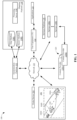
- FIG. 4A, FIG. 4B , and FIG. 4C are diagrams 400A-400C, each of which depicts an exemplary trajectory T including a plurality of data points and a set of visible points, with a different data point selected as an observation point, in accordance with an embodiment of the disclosure.
- the trajectory T includes a plurality of data points P1, P2, ... P15 (also collectively referred to as plurality of data points P), with a first data point P1 (indicated with a ring outside the point) selected as the observation point.
- P1, P2, ... P15 also collectively referred to as plurality of data points P
- first data point P1 indicated with a ring outside the point
- the trajectory T includes the plurality of data points P, with a second data point P2 (Indicated with a ring outside the point) selected as the observation point, and so on. Further, in FIG. 4C , the trajectory T includes the plurality of data points P, with a fifteenth data point P15 (indicated with a ring outside the point) selected as the observation point, and so on.
- Each data point of the plurality of data points P of the trajectory T may be associated with an associated set of visible points.
- a first data point may be visible from a second data point, if the first data point lies within a visibility polygon of the second data point in the (lat, lon)-plane that may be defined as a set of all data points in a location that can be connected to the second data point with a straight line without intersecting any obstacles.
- ray-tracing methods from the field of computer graphics/gaming may be utilized to assess such a condition.
- the set of visible points may provide indications about a vehicle movement outside of visibility zone based on map data associated with a location of the trajectory.
- the trajectory T may be portioned into disjoint sequences Ti of probes such that within each such sequence Ti, all the data points have the same set of visible points.
- the sequence Ti may also be called a visibility partition of the trajectory T.
- a visibility partition of the dataset may be obtained by portioning the trajectory in the above manner.
- FIG. 4A, FIG. 4B and FIG. 4C depict partitions based on visibility and map data associated with a location of the trajectory.
- the changing points may be identified as data points P6, P10, and P14 (indicated with a ring around the point).
- the changing points P6, P10, and P14 may be identified based on a comparison between location information of the changing point and location information of a corresponding previous data point from the plurality of data points P.
- the data points P6, P10, and P14 may be identified as the changing points since the location information of the said changing point happens to correspond to a different set of visible points when compared to the location information of the corresponding previous data point.
- the data points P6, P10, and P14 may be identified as the changing points since the data points P6, P10, and P14 happen to be at a decision point (e.g. corner, intersection) where the next set of visible points changes, for example where the trajectory T of the vehicle takes a turn and the previous set of visible points are no longer visible, as can be seen in FIG. 5A .
- FIG. 5C is a diagram 500C which depicts an outcome of the anonymization process, in accordance with an embodiment of the disclosure.
- FIG. 5C is explained together with FIG. 3 , FIG. 4A , FIG. 4B , FIG. 4C , FIG. 5A, and FIG. 5B .
- the changing points P6, P10, and P14 may mark a starting point of a respective set of visible points for the trajectory T. Further, as shown in FIG.
- the data points P1, P2, P3, P4, P5 may form the first set of visible points T1
- the data points P6, P7, P8, P9 may form the second set of visible points T2
- the data points P10, P11, P12, P13 may form the third set of visible points T3
- the data points P14, P15 may form the fourth set of visible points T4.
- the trajectory T may be processed to introduce a gap overlapping with the changing point, resulting in at least one sub-trajectory.
- the second portion of the trajectory comprising points P7, P8 and P9 may be processed to introduce a gap G1 (in place of the changing point P6).
- the portion of the trajectory comprising points P10, P11 and P12 may be processed to introduce a gap G2 (in place of the changing point P10).
- the portion of the trajectory comprising P14 may be processed to introduce a gap G3 (in place of the changing point P14).
- multiple data points may be replaced by the gap, and as such the gap length may vary depending on the number of data points that are replaced by the associated gap.
- each of the plurality of resulting sub-trajectories may be outputted with a unique ID. As shown in FIG.
- the first sub-trajectory T1 may be assigned an ID-1
- the second sub-trajectory T2 may be assigned an ID-2
- the third sub-trajectory T3 may be assigned an ID-3
- the fourth sub-trajectory T4 may be assigned an ID-4.
- the present example describes removing or replacing the changing points by positioning gaps.
- the gaps may be positioned to overlap a part of a changing point, or cover (partially or completely) data points neighboring to the changing point.
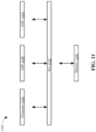
- FIG. 5D is a diagram 500D which depicts an exemplary scenario for an anonymized trajectory corresponding to trajectory T (corresponding to FIGs. 4A-4C ), in accordance with an embodiment.
- data points P3, P4, P5, P6, P7, P8, P9, P10, P11 represent a sub-trajectory remained after anonymization, and the remaining points (P1, P2, P12, P13, P14, P15) represent deleted points from the raw trajectory. It is presumed that every partition Ti of the trajectory T is in sequences, such that each such sequence provides a minimum amount of information to an observer placed at any point of the trajectory T.
- I S ⁇ length T i ⁇ S ⁇ length S ⁇ T i ⁇ S length S
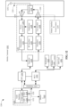
- FIG. 6 is a flowchart 600 that illustrates an exemplary method of generating sub-trajectories for a trajectory, in accordance with an embodiment of the disclosure.
- FIG. 6 is explained in conjunction with elements from FIG. 1 , FIG. 2 , FIG. 3 , FIG. 4A , FIG. 4B , FIG. 4C , and FIG. 5A, FIG. 5B , FIG. 5C, and FIG. 5D .
- FIG. 6 there is shown a flowchart 600.
- the operations of the exemplary method may be executed by any computing system, for example, by the anonymization platform 102 of FIG. 1 .
- the operations of the flowchart 600 may start at 602.
- an observation point associated with a data point from the plurality of data points may be selected.
- an observation point associated with each of the plurality of data points may be selected during the method, at different stages of the method.
- step 704 of outputting the processed sub-trajectory in place of a part of the trajectory may be performed for each iteration of generating the sub-trajectory for each of the data points selected in association with the observation point, calculating a set of visible points associated with the observation point, and identifying a changing point based on the set of visible points.
- the UE 112 is configured with various sensors for generation of the sensor data, related geographic data, etc.
- the sensors may include a global positioning sensor for gathering location data (e.g., GPS, GALILEO, BEIDOU, GLONASS), IMUs, a network detection sensor for detecting wireless signals or receivers for different short-range communications (e.g., Bluetooth, Wi-Fi, Li-Fi, near field communication (NFC) etc.), temporal information sensors, a camera/imaging sensor for gathering image data (e.g., the camera sensors may automatically capture road sign information, images of road obstructions, etc. for analysis), an audio recorder for gathering audio data, velocity sensors mounted on steering wheels of the vehicles, switch sensors for determining whether one or more vehicle switches are engaged, and the like.
- sensors of the UE 112 may include light sensors, orientation sensors augmented with height sensors and acceleration sensor, tilt sensors to detect the degree of incline or decline (e.g., slope) along a path of travel, moisture sensors, pressure sensors, etc.
- sensors about the perimeter of the UE 112 may detect the relative distance of the device or vehicle from a lane or roadway, the presence of other vehicles, pedestrians, traffic lights, potholes and any other objects, or a combination thereof.
- the sensors may detect weather data, traffic information, or a combination thereof.
- the UE 112 may include GPS or other satellite-based receivers to obtain geographic coordinates from positioning satellites for determining current location and time. Further, the location can be determined by visual odometry, triangulation systems such as A-GPS, Cell of Origin, or other location extrapolation technologies.
- the network 110 of the system 100 includes one or more networks such as a data network, a wireless network, a telephony network, or any combination thereof.
- the data network may be any local area network (LAN), metropolitan area network (MAN), wide area network (WAN), a public data network (e.g., the Internet), short range wireless network, or any other suitable packet-switched network, such as a commercially owned, proprietary packet-switched network, e.g., a proprietary cable or fiber-optic network, and the like, or any combination thereof.
- the wireless network may be, for example, a cellular network and may employ various technologies including enhanced data rates for global evolution (EDGE), general packet radio service (GPRS), global system for mobile communications (GSM), Internet protocol multimedia subsystem (IMS), universal mobile telecommunications system (UMTS), etc., as well as any other suitable wireless medium, e.g., worldwide interoperability for microwave access (WiMAX), Long Term Evolution (LTE) networks, 5GNew Radio networks, code division multiple access (CDMA), wideband code division multiple access (WCDMA), wireless fidelity (Wi-Fi), wireless LAN (WLAN), Bluetooth ® , Internet Protocol (IP) data casting, satellite, mobile ad-hoc network (MANET), and the like, or any combination thereof.
- EDGE enhanced data rates for global evolution
- GPRS general packet radio service
- GSM global system for mobile communications
- IMS Internet protocol multimedia subsystem
- UMTS universal mobile telecommunications system
- any other suitable wireless medium e.g., worldwide interoperability for
- the UE 112 is configured as the probe device 104.
- the UE 112 comprises the probe device 104.
- the anonymization platform 102 is configured to run locally on the UE 112 or equivalently the probe device 104, such as in the form of an application or service installed on any of the UE 112 or the probe device 104.
- a protocol includes a set of rules defining how the network nodes within the network 110 interact with each other based on information sent over the communication links.
- the protocols are effective at different layers of operation within each node, from generating and receiving physical signals of various types, to selecting a link for transferring those signals, to the format of information indicated by those signals, to identifying which software application executing on a computer system sends or receives the information.
- the conceptually different layers of protocols for exchanging information over a network are described in the Open Systems Interconnection (OSI) Reference Model.
- the map database 108A can be based on Light Detection and Ranging (LiDAR) or equivalent technology to collect billions of 3D points and model road surfaces and other map features down to the number lanes and their widths.
- the HD mapping data e.g., HD data records 912
- other mapping data of the map database 108A capture and store details such as but not limited to road attributes and/or other features related to generating speed profile data. These details include but are not limited to road width, number of lanes, turn maneuver representations/guides, traffic lights, light timing/stats information, slope and curvature of the road, lane markings, roadside objects such as signposts, including what the signage denotes.
- the HD mapping data enable highly automated vehicles to precisely localize themselves on the road.
- geographic features are represented using polylines and/or polygons (e.g., two-dimensional features) or polygon extrusions (e.g., three-dimensional features).
- these polylines/polygons can also represent ground truth or reference features or objects (e.g., signs, road markings, lane lines, landmarks, topological features, buildings, building footprints, city blocks etc.) used for determining visibility context criteria.
- the polylines or polygons can correspond to the boundaries or edges of the respective geographic features.
- a two-dimensional polygon can be used to represent a footprint of the building, and a three-dimensional polygon extrusion can be used to represent the three-dimensional surfaces of the building.
- topographical features such as hills, depressions, water bodies, etc.
- a three-dimensional shape e.g. polygon extrusion, approximate shape including elevation data.
- polygons and polygon extrusions as used herein can be used interchangeably.
- data pertaining to such geographical features may be stored as node data records 904, road segment or link data records 906, POI data records 908, feature data records 910, and HD mapping data records 912, for example.
- the following terminology applies to the representation of geographic features in the map database 108A.
- Node A point that terminates a link.
- Line segment A straight line connecting two points.
- Link (or “edge”) - A contiguous, non-branching string of one or more line segments terminating in a node at each end.
- Shape point A point along a link between two nodes (e.g., used to alter a shape of the link without defining new nodes).
- special purpose hardware such as an application specific integrated circuit (ASIC) 1018
- ASIC application specific integrated circuit
- the special purpose hardware is configured to perform operations not performed by processor 1002 quickly enough for special purposes.
- application specific ICs include graphics accelerator cards for generating images for display 1014, cryptographic boards for encrypting and decrypting messages sent over a network, speech recognition, and interfaces to special external devices, such as robotic arms and medical scanning equipment that repeatedly perform some complex sequence of operations that are more efficiently implemented in hardware.
- the processor 1104 may also be accompanied with one or more specialized components to perform certain processing functions and tasks such as one or more digital signal processors (DSP) 1108, or one or more application-specific integrated circuits (ASIC) 1110.
- DSP digital signal processors
- ASIC application-specific integrated circuits
- a DSP 1108 typically is configured to process real-world signals (e.g., sound) in real time independently of the processor 1104.
- an ASIC 1110 can be configured to perform specialized functions not easily performed by a general purposed processor.
- Other specialized components to aid in performing the inventive functions described herein include one or more field programmable gate arrays (FPGA) (not shown), one or more controllers (not shown), or one or more other special-purpose computer chips.
- FPGA field programmable gate arrays
- An optionally incorporated SIM card 1226 carries, for instance, important information, such as the cellular phone number, the carrier supplying service, subscription details, and security information.
- the SIM card 1226 serves primarily to identify the mobile station 1202 on a radio network.
- the card 1226 also contains a memory for storing a personal telephone number registry, text messages, and user specific mobile station settings.
Landscapes
- Engineering & Computer Science (AREA)
- Computer Networks & Wireless Communication (AREA)
- Signal Processing (AREA)
- Computer Security & Cryptography (AREA)
- Mechanical Engineering (AREA)
- Traffic Control Systems (AREA)
Applications Claiming Priority (1)
| Application Number | Priority Date | Filing Date | Title |
|---|---|---|---|
| US18/399,066 US12604182B2 (en) | 2023-12-28 | 2023-12-28 | Method and apparatus for generating sub-trajectories for a trajectory |
Publications (1)
| Publication Number | Publication Date |
|---|---|
| EP4580219A1 true EP4580219A1 (de) | 2025-07-02 |
Family
ID=93926209
Family Applications (1)
| Application Number | Title | Priority Date | Filing Date |
|---|---|---|---|
| EP24222358.4A Pending EP4580219A1 (de) | 2023-12-28 | 2024-12-20 | Methode und gerät zur erzeugung von untertrajektorien für eine trajektorie |
Country Status (2)
| Country | Link |
|---|---|
| US (1) | US12604182B2 (de) |
| EP (1) | EP4580219A1 (de) |
Citations (2)
| Publication number | Priority date | Publication date | Assignee | Title |
|---|---|---|---|---|
| US20210372801A1 (en) * | 2020-05-29 | 2021-12-02 | Here Global B.V. | Method and apparatus for trajectory anonymization based on negative gapping |
| US20210383022A1 (en) * | 2020-06-05 | 2021-12-09 | Here Global B.V. | Method and apparatus for trajectory anonymization based on a trajectory exchange twist |
Family Cites Families (4)
| Publication number | Priority date | Publication date | Assignee | Title |
|---|---|---|---|---|
| US11562168B2 (en) | 2018-07-16 | 2023-01-24 | Here Global B.V. | Clustering for K-anonymity in location trajectory data |
| US11042648B2 (en) | 2019-07-17 | 2021-06-22 | Here Global B.V. | Quantification of privacy risk in location trajectories |
| US11526628B2 (en) | 2020-05-29 | 2022-12-13 | Here Global B.V. | Method and apparatus for device-side trajectory anonymization based on negative gapping |
| US11645730B2 (en) * | 2020-11-16 | 2023-05-09 | Here Global B.V. | Method, apparatus, and computer program product for identifying privacy risks in datasets |
-
2023
- 2023-12-28 US US18/399,066 patent/US12604182B2/en active Active
-
2024
- 2024-12-20 EP EP24222358.4A patent/EP4580219A1/de active Pending
Patent Citations (2)
| Publication number | Priority date | Publication date | Assignee | Title |
|---|---|---|---|---|
| US20210372801A1 (en) * | 2020-05-29 | 2021-12-02 | Here Global B.V. | Method and apparatus for trajectory anonymization based on negative gapping |
| US20210383022A1 (en) * | 2020-06-05 | 2021-12-09 | Here Global B.V. | Method and apparatus for trajectory anonymization based on a trajectory exchange twist |
Non-Patent Citations (1)
| Title |
|---|
| LIU XIANGWEN ET AL: "SLAT: Sub-Trajectory Linkage Attack Tolerance Framework for Privacy-Preserving Trajectory Publishing", 2018 INTERNATIONAL CONFERENCE ON NETWORKING AND NETWORK APPLICATIONS (NANA), IEEE, 12 October 2018 (2018-10-12), pages 298 - 303, XP033522220, DOI: 10.1109/NANA.2018.8648724 * |
Also Published As
| Publication number | Publication date |
|---|---|
| US12604182B2 (en) | 2026-04-14 |
| US20250220415A1 (en) | 2025-07-03 |
Similar Documents
| Publication | Publication Date | Title |
|---|---|---|
| US11651244B2 (en) | Method and apparatus for predicting sensor error | |
| EP3293489B1 (de) | Verfahren und vorrichtung zur bereitstellung von bahnbündeln für eine kartendatenanalyse | |
| US11566906B2 (en) | Method, apparatus, and system for generating vehicle paths in a limited graph area | |
| US11756417B2 (en) | Method, apparatus, and system for detecting road incidents | |
| EP3739293B1 (de) | Verfahren und vorrichtung zur bereitstellung von fahrspurverbindungsdaten für eine kreuzung | |
| EP4001843B1 (de) | Verfahren, vorrichtung und system zur erzeugung von doppelt digitalisierten karten | |
| US12253365B2 (en) | Method, apparatus, and system for aggregating a route based on high-resolution sampling | |
| EP3798576A2 (de) | Verfahren und vorrichtung zur bereitstellung eines kartenabgleichers mit toleranz gegenüber falschen kartenmerkmalen | |
| US10984552B2 (en) | Method, apparatus, and system for recommending ground control points for image correction | |
| US10535006B2 (en) | Method, apparatus, and system for providing a redundant feature detection engine | |
| US20200090503A1 (en) | Method, apparatus, and system for real-time detection of road closures | |
| US20220299341A1 (en) | Method, apparatus, and system for providing route-identification for unordered line data | |
| US11386650B2 (en) | Method, apparatus, and system for detecting and map coding a tunnel based on probes and image data | |
| US20210404818A1 (en) | Method, apparatus, and system for providing hybrid traffic incident identification for autonomous driving | |
| US11946769B2 (en) | Method, apparatus, and system for identifying special areas and cleaning-up map data | |
| US12236691B2 (en) | Method, apparatus, and system for estimating a lane width | |
| US20220383024A1 (en) | Method, apparatus, and system for detecting and coding a road stack interchange based on image data | |
| US20220252422A1 (en) | Method, apparatus, and system for constructing a high-resolution map for geospatial big data processing | |
| US20230266142A1 (en) | Method, apparatus, and system for reconstructing a road linear feature | |
| US20240151541A1 (en) | Method and apparatus for risk computation of concealed areas on a street | |
| US12604182B2 (en) | Method and apparatus for generating sub-trajectories for a trajectory | |
| US20240428177A1 (en) | System and method for tracking shipments | |
| US12242519B2 (en) | Method, apparatus, and system for providing linear feature detection of cartographic features | |
| US11885636B2 (en) | Method, apparatus, and system for automatically coding and verifying human settlement cartographic features | |
| US20240191997A1 (en) | Method, apparatus, and system for providing a signed angle metric for mapmatching based on probe data |
Legal Events
| Date | Code | Title | Description |
|---|---|---|---|
| PUAI | Public reference made under article 153(3) epc to a published international application that has entered the european phase |
Free format text: ORIGINAL CODE: 0009012 |
|
| STAA | Information on the status of an ep patent application or granted ep patent |
Free format text: STATUS: THE APPLICATION HAS BEEN PUBLISHED |
|
| AK | Designated contracting states |
Kind code of ref document: A1 Designated state(s): AL AT BE BG CH CY CZ DE DK EE ES FI FR GB GR HR HU IE IS IT LI LT LU LV MC ME MK MT NL NO PL PT RO RS SE SI SK SM TR |
|
| STAA | Information on the status of an ep patent application or granted ep patent |
Free format text: STATUS: REQUEST FOR EXAMINATION WAS MADE |
|
| 17P | Request for examination filed |
Effective date: 20251223 |
|
| GRAJ | Information related to disapproval of communication of intention to grant by the applicant or resumption of examination proceedings by the epo deleted |
Free format text: ORIGINAL CODE: EPIDOSDIGR1 |
|
| GRAP | Despatch of communication of intention to grant a patent |
Free format text: ORIGINAL CODE: EPIDOSNIGR1 |
|
| GRAP | Despatch of communication of intention to grant a patent |
Free format text: ORIGINAL CODE: EPIDOSNIGR1 |
|
| STAA | Information on the status of an ep patent application or granted ep patent |
Free format text: STATUS: GRANT OF PATENT IS INTENDED |
|
| INTG | Intention to grant announced |
Effective date: 20260217 |