EP4581965A2 - Dispositif de fourniture d'aérosol - Google Patents
Dispositif de fourniture d'aérosol Download PDFInfo
- Publication number
- EP4581965A2 EP4581965A2 EP25178635.6A EP25178635A EP4581965A2 EP 4581965 A2 EP4581965 A2 EP 4581965A2 EP 25178635 A EP25178635 A EP 25178635A EP 4581965 A2 EP4581965 A2 EP 4581965A2
- Authority
- EP
- European Patent Office
- Prior art keywords
- heater component
- support
- insulating member
- coil
- axis
- Prior art date
- Legal status (The legal status is an assumption and is not a legal conclusion. Google has not performed a legal analysis and makes no representation as to the accuracy of the status listed.)
- Pending
Links
Images


Classifications
-
- A—HUMAN NECESSITIES
- A24—TOBACCO; CIGARS; CIGARETTES; SIMULATED SMOKING DEVICES; SMOKERS' REQUISITES
- A24F—SMOKERS' REQUISITES; MATCH BOXES; SIMULATED SMOKING DEVICES
- A24F40/00—Electrically operated smoking devices; Component parts thereof; Manufacture thereof; Maintenance or testing thereof; Charging means specially adapted therefor
- A24F40/40—Constructional details, e.g. connection of cartridges and battery parts
- A24F40/46—Shape or structure of electric heating means
-
- A—HUMAN NECESSITIES
- A24—TOBACCO; CIGARS; CIGARETTES; SIMULATED SMOKING DEVICES; SMOKERS' REQUISITES
- A24F—SMOKERS' REQUISITES; MATCH BOXES; SIMULATED SMOKING DEVICES
- A24F40/00—Electrically operated smoking devices; Component parts thereof; Manufacture thereof; Maintenance or testing thereof; Charging means specially adapted therefor
- A24F40/20—Devices using solid inhalable precursors
-
- A—HUMAN NECESSITIES
- A24—TOBACCO; CIGARS; CIGARETTES; SIMULATED SMOKING DEVICES; SMOKERS' REQUISITES
- A24F—SMOKERS' REQUISITES; MATCH BOXES; SIMULATED SMOKING DEVICES
- A24F40/00—Electrically operated smoking devices; Component parts thereof; Manufacture thereof; Maintenance or testing thereof; Charging means specially adapted therefor
- A24F40/40—Constructional details, e.g. connection of cartridges and battery parts
- A24F40/46—Shape or structure of electric heating means
- A24F40/465—Shape or structure of electric heating means specially adapted for induction heating
-
- A—HUMAN NECESSITIES
- A24—TOBACCO; CIGARS; CIGARETTES; SIMULATED SMOKING DEVICES; SMOKERS' REQUISITES
- A24F—SMOKERS' REQUISITES; MATCH BOXES; SIMULATED SMOKING DEVICES
- A24F40/00—Electrically operated smoking devices; Component parts thereof; Manufacture thereof; Maintenance or testing thereof; Charging means specially adapted therefor
- A24F40/50—Control or monitoring
- A24F40/51—Arrangement of sensors
-
- H—ELECTRICITY
- H05—ELECTRIC TECHNIQUES NOT OTHERWISE PROVIDED FOR
- H05B—ELECTRIC HEATING; ELECTRIC LIGHT SOURCES NOT OTHERWISE PROVIDED FOR; CIRCUIT ARRANGEMENTS FOR ELECTRIC LIGHT SOURCES, IN GENERAL
- H05B6/00—Heating by electric, magnetic or electromagnetic fields
- H05B6/02—Induction heating
- H05B6/10—Induction heating apparatus, other than furnaces, for specific applications
- H05B6/105—Induction heating apparatus, other than furnaces, for specific applications using a susceptor
- H05B6/108—Induction heating apparatus, other than furnaces, for specific applications using a susceptor for heating a fluid
-
- H—ELECTRICITY
- H05—ELECTRIC TECHNIQUES NOT OTHERWISE PROVIDED FOR
- H05B—ELECTRIC HEATING; ELECTRIC LIGHT SOURCES NOT OTHERWISE PROVIDED FOR; CIRCUIT ARRANGEMENTS FOR ELECTRIC LIGHT SOURCES, IN GENERAL
- H05B6/00—Heating by electric, magnetic or electromagnetic fields
- H05B6/02—Induction heating
- H05B6/36—Coil arrangements
-
- A—HUMAN NECESSITIES
- A24—TOBACCO; CIGARS; CIGARETTES; SIMULATED SMOKING DEVICES; SMOKERS' REQUISITES
- A24D—CIGARS; CIGARETTES; TOBACCO SMOKE FILTERS; MOUTHPIECES OF CIGARS OR CIGARETTES; MANUFACTURE OF TOBACCO SMOKE FILTERS OR MOUTHPIECES
- A24D1/00—Cigars; Cigarettes
- A24D1/20—Cigarettes specially adapted for simulated smoking devices
-
- A—HUMAN NECESSITIES
- A24—TOBACCO; CIGARS; CIGARETTES; SIMULATED SMOKING DEVICES; SMOKERS' REQUISITES
- A24F—SMOKERS' REQUISITES; MATCH BOXES; SIMULATED SMOKING DEVICES
- A24F40/00—Electrically operated smoking devices; Component parts thereof; Manufacture thereof; Maintenance or testing thereof; Charging means specially adapted therefor
- A24F40/70—Manufacture
-
- B—PERFORMING OPERATIONS; TRANSPORTING
- B29—WORKING OF PLASTICS; WORKING OF SUBSTANCES IN A PLASTIC STATE IN GENERAL
- B29K—INDEXING SCHEME ASSOCIATED WITH SUBCLASSES B29B, B29C OR B29D, RELATING TO MOULDING MATERIALS OR TO MATERIALS FOR MOULDS, REINFORCEMENTS, FILLERS OR PREFORMED PARTS, e.g. INSERTS
- B29K2071/00—Use of polyethers, e.g. PEEK, i.e. polyether-etherketone or PEK, i.e. polyetherketone or derivatives thereof, as moulding material
Definitions
- the present invention relates to a support for a heater component of an aerosol provision device and an aerosol provision device including the support.
- the present invention also relates to an aerosol provision device, an aerosol provision system and an article comprising aerosol generating material.
- Smoking articles such as cigarettes, cigars and the like burn tobacco during use to create tobacco smoke. Attempts have been made to provide alternatives to these articles that burn tobacco by creating products that release compounds without burning. Examples of such products are heating devices which release compounds by heating, but not burning, the material.
- the material may be for example tobacco or other non-tobacco products, which may or may not contain nicotine.
- a support for a heater component of an aerosol provision device wherein the support defines an axis and is configured to engage an end of the heater component to hold the heater component substantially parallel to the axis at a predetermined distance from a coil, and wherein the support defines a channel to receive a wire of a temperature sensor, the channel defining an opening into a space between the heater component and the coil.
- an aerosol provision device comprising:
- an aerosol provision device comprising:
- an aerosol provision device comprising:
- an aerosol provision device comprising:
- Apparatus that heats aerosol generating material to volatilise at least one component of the aerosol generating material, typically to form an aerosol which can be inhaled, without burning or combusting the aerosol generating material.
- Such apparatus is sometimes described as an "aerosol generating device", an “aerosol provision device”, a “heat-not-burn device”, a “tobacco heating product device” or a “tobacco heating device” or similar.
- e-cigarette devices which typically vaporise an aerosol generating material in the form of a liquid, which may or may not contain nicotine.
- An aerosol provision device can receive an article comprising aerosol generating material for heating.
- An "article” in this context is a component that includes or contains in use the aerosol generating material, which is heated to volatilise the aerosol generating material, and optionally other components in use.
- a user may insert the article into the aerosol provision device before it is heated to produce an aerosol, which the user subsequently inhales.
- the article may be, for example, of a predetermined or specific size that is configured to be placed within a heating chamber of the device which is sized to receive the article.
- a first aspect of the present disclosure defines a support for a heater component (such as a susceptor) of an aerosol provision device.
- a susceptor is an electrically conducting object, which is heated via electromagnetic induction.
- An article comprising aerosol generating material can be received within the heater component. Once heated, the heater component transfers heat to the aerosol generating material, which releases the aerosol.
- the device can monitor the temperature of the heater component in one or more locations, as it is being heated. This may be useful because the aerosol generating material may need to be heated to a specific temperature. For example, if the temperature of the heater component is too high, the aerosol generating material may overheat, which can impact the taste/flavour of the aerosol. If the temperature of the heater component is too low, the volume of aerosol generated may be too low. Accordingly, it may be useful to control and monitor the temperature of the heater component during heating.
- one or more temperature sensors may be in contact with, or positioned near, the heater component.
- the temperature sensor may be a thermocouple, for example.
- One or more wires may connect the temperature sensor to other electronic circuitry within the aerosol provision device, and the wires must therefore be routed from the heater component, to another location within the device.
- the heater component may be a susceptor, and the heater component may be heated by a coil (such as an inductor coil).
- a coil such as an inductor coil
- An inductor coil is configured to generate a varying magnetic field.
- a susceptor is heatable by penetration with the varying magnetic field.
- the heater component may be surrounded by one or more components, such as an insulating member which can be arranged coaxially with the heater component.
- the insulating member can help insulate other components of the device from the heat generated by the heater component.
- the insulating member may also support one or more coils which are positioned around, and spaced apart from, the heater component.
- the wires from the temperature sensors are routed through a surface of the insulating member.
- one or more through holes may be formed through the insulating member, and the wires passed through the through hole.
- the through hole can weaken the structural integrity of the insulating member.
- the insulating member is more prone to damage.
- the hole can also reduce the insulative effect provided by the insulating member. Thus, heat can escape from the space between the heater component and the insulating member.
- the present invention relates to a support which defines a channel through which the wire of a temperature sensor can pass.
- the support is an element which holds the heater component in place within the device.
- the channel formed in the support defines an opening into a space between the heater component and coil/insulating member. This means that the wire does not need to be routed through the insulating member so that its structural integrity is not compromised.
- One or more wires may be routed through the channel.
- the support also known as a "cleanout tube”
- the support defines an axis and is configured to engage an end of the heater component to hold the heater component substantially parallel to the axis at a predetermined distance from a coil.
- the support therefore holds the heater component in place within the device, relative to the coil.
- the wire can therefore be routed along the heater component (generally in the direction of the axis), and through the channel so that it can extend out of the space between the heater component and the coil.
- the channel may extend substantially parallel to the axis.
- the channel is formed through a portion of the support in a direction that is substantially parallel to the axis.
- the wire once received in the channel, therefore extends in a direction substantially parallel to the axis. This construction can be easier to manufacture, and also minimises length of wire used because it defines the shortest route into the space between the heater component and the coil/insulating member. In other examples the channel may not be parallel to the axis.
- the channel may be open along its length. In other words, the channel may be open around its perimeter. In contrast, a channel that is closed around its perimeter would be a through hole formed through a portion of the support.
- a channel which is open along its length can be easily manufactured and may allow the device to be assembled quicker. For example, the wire can be slotted into the channel, rather than requiring the wire to be threaded through a hole.
- the channel can have a depth which is measured in a direction perpendicular to the axis.
- the channel may therefore define a notch formed in a portion of the support.
- the channel may have a depth of less than about 5mm, or less than about 3mm.
- the channel has a depth of less than about 2mm, such as about 1.7mm. If the channel is too deep, then heat may more easily escape from the space between the heater component and coil. If the channel is too shallow, then the wire may need to be angled with respect to the axis and heater component, which may bend or break the wire. The above dimensions provide a good balance between these considerations.
- the channel can have a width which is measured in a direction perpendicular to the axis and the depth.
- the channel may have a width of less than about 2mm, or less than about 1mm.
- the channel has a width of about 0.9mm. If the channel is too wide, then heat may more easily escape from the space between the heater component and coil.
- the support may comprise a first portion, and the channel may be formed through the first portion.
- the first portion may have a first cross section, and may be arranged generally perpendicular to the axis.
- the first portion may be substantially circular in cross section, although other cross-sectional shapes are possible.
- the first portion may have a perimeter which extends around the axis.
- the first portion may have a first depth, measured in a direction parallel to the axis.
- the channel therefore has a length equal to the first depth if the channel is formed parallel to the axis, or has a length greater than the first depth if the channel is not parallel to the axis.
- the channel is a notch at an outer perimeter of the first portion. In other examples however, the channel is closed around its perimeter such that a through hole is formed through the first portion.
- the inner diameter of the though hole can be substantially the same as the outer diameter of the wire, which thereby reduces heat loss from the heater component.
- the second portion may not comprise a channel. Instead, the wire may be routed around the second portion.
- the resilient member encloses/encircles the wire.
- the resilient member extends around the wire.
- the wire passes inside the "O". This arrangement can help keep the wires taught so that they are less likely to be damaged, and/or can hold the wires in the channel. Holding the wires in the channel can help stop the temperature sensor from being pulled away from the surface of the heater component.
- the second aspect of the present disclosure defines an aerosol provision device comprising a support as described above.
- the device further comprises a heater component engaged with the support at one end, and a coil extending around the heater component, where the coil is configured to heat the heater component (via a magnetic field, for example).
- the device further comprises a temperature sensor for sensing the temperature of the heater component, where the temperature sensor is positioned in a space between the coil and the heater component.
- the device further comprises a wire positioned in the channel of the support and connected to the temperature sensor.
- the device may define a longitudinal axis that is substantially parallel to the axis of the support.
- the device may define a proximal end, and a distal end.
- the proximal end of the device may be held closer to a user's mouth than the distal end.
- aerosol may be drawn towards the proximal end of the device.
- the support engages the distal end of the heater component.
- the device may further comprise an insulating member.
- the support may comprise a first portion, where the channel is formed through the first portion.
- the insulating member may surround the heater component and abut at least part of the first portion of the support, thereby to position the insulating member at a predetermined radial distance outward from the heater component.
- the insulating member surrounds the first portion of the support.
- the insulating member is arranged between the heater component and the coil, and is spaced apart from the axis by a first distance.
- a perimeter of the first portion is spaced apart from the axis by a second distance.
- the first distance may be substantially equal to the second distance.
- the first distance may be slightly greater than the second distance, so that the first portion may fit inside the hollow insulating member.
- the perimeter of the first portion may abut the inner surface of the insulating member.
- the outer edge of the resilient member may be spaced apart from the axis by a third distance, the third distance being substantially equal to the first distance.
- the resilient member may abut the inner surface of the insulating member.
- the device comprises a first coil and a second coil.
- the first coil may be used to heat a first portion of the heater component
- the second coil may be used to heat a second portion of the heater component.
- the device comprises a first temperature sensor arranged to sense a temperature of the first portion of the heater component, and a second temperature sensor arranged to sense a temperature of the second portion of the heater component.
- Each temperature sensor may be associated with two wires, and the support may define four channels, where each channel receives a wire.
- the device may comprise a second temperature sensor for sensing the temperature of the heater component, wherein the second temperature sensor is positioned in the space between the coil and the heater component and a second wire is connected to the second temperature sensor, wherein the support defines a second channel to receive the second wire.
- the temperature sensor is in contact with the heater component. This allows for a more accurate reading of the heater component temperature.
- a fourth aspect of the present disclosure relates to the positioning of a heater component in relation to first and second supports.
- the first and second supports engage opposite ends of the heater component and hold the heater component in place within the aerosol provision device.
- One or more coils are positioned away from the heater component by a predetermined distance. In some arrangements, the one or more coils extend around the heater component.
- the heater component may be known as a susceptor, in some examples.
- the first and second supports ensure that the heater component is adequately positioned in relation to the one or more coils. By keeping the distance between the heater component and coil constant over time, the heater component can be heated effectively each time the device is used. Furthermore, because the first and second supports are not integral with the heater component, heat is transferred to the first and second supports at a slower rate. This can help insulate other components of the device from the heated heater component. In other examples, however, the first and second supports are integral with the heater component. For example, they may be moulded together. While this may increase the rate at which heat conducts away from the heater component, it can more robustly hold the heater component in place.
- the first and second supports may comprise a plastics material.
- they may be entirely, or partially made from one or more plastics materials.
- the portion of the support which engages the heater component comprises the plastics material.
- Plastics are good thermal insulators, are relatively inexpensive, are lightweight, and can easily be moulded into the required shape to engage the heater component.
- the plastics material comprises polyether ether ketone (PEEK).
- PEEK is a particularly suitable material for the first and second supports because it has a thermal conductivity of about 0.32W/mK, a melting point of about 343°C and is not electrically conductive, so will not generate heat as a result of the coils.
- the PEEK is Victrex ® PEEK 450G.
- the first and second supports have a melting point of greater than about 300°C.
- the first and second supports have a melting point of greater than about 340°C.
- the one or more coils are configured to heat the heater component to a temperature of between about 240°C and about 280°C.
- the at least one coil may be configured to heat the heater component to a first temperature and the first and second supports have a melting point of a second temperature, wherein the second temperature is greater than the first temperature by at least about 60 °C. This ensures that the first and second supports remain structurally stable, and do not begin to weaken as the temperature of heater component increases.
- the first temperature is 250°C and the second temperature is 343°C.
- the first temperature is 280°C and the second temperature is 343°C.
- the coils may operate in two modes. In a first mode the heater is heated to a lower temperature than in a second mode.
- the aerosol provision device further comprises an insulating member extending around the heater component, wherein the insulating member is positioned away from the heater component to provide an air gap around the heater component.
- the insulating member may be positioned between the at least one coil and the heater component such that the at least one coil extends around the insulating member.
- the coil may be in contact with the insulating member.
- a further air gap may be provided between the insulating member and the coil.
- Such an arrangement provides a device with improved insulation.
- the specific order of the air gap and the insulating member provides improved insulation from the heated heater component.
- the air gap helps insulate the insulating member from the heat.
- the first and second supports, the air gap and the insulating member help insulate other components of the device from the heat.
- the supports, air gap and insulating member reduce any heating of the coil, electronics, and/or battery by the heater component.
- the insulating member is positioned away from the receptacle/heater component to provide an air gap.
- the inner surface of the insulating member is spaced apart from the outer surface of the heater component. This means that an air gap surrounds the outer surface of the heater component, and the heater component is not in contact with the insulating member in this region. Any contact could provide a thermal bridge along which heat could flow.
- the heater component is elongate and defines an axis, such as a longitudinal axis.
- the insulating member extends around the heater component and the axis in an azimuthal direction.
- the insulating member is therefore positioned radially outward from the heater component, for example the insulating member may be coaxial with the heater component.
- This radial direction is defined as being perpendicular to the axis of the heater component.
- the coil extends around the insulating member and is positioned radially outwards from both the heater component and the insulating member. The coil may be coaxial with the insulating member and the heater component.
- the insulating member is thermally insulating.
- it may comprise a plastics material and may have low thermal conductivity such as a thermal conductivity of less than about 0.5W/mK.
- the plastics material is PEEK, and may therefore be made from the same material as the first and second supports.
- the insulating member may abut at least one of the first support and the second support such that the insulating member is held substantially parallel to the axis.
- the insulating member may extend between the first and second supports such that a first end of the insulating member abuts the first support and a second end of the insulating member abuts the second support.
- the first and second supports may therefore also support the insulating member as well as the heater component, which reduces the number of components in the device.
- the first support may comprise a first resilient member and the resilient member may abut an inner surface of the insulating member.
- the insulating member may therefore extend around a portion of the first support which comprises the first resilient member.
- the resilient member may be an O-ring, for example.
- the resilient member may extend around an outer surface of the first support. When the resilient member abuts the inner surface of the insulating member it can help seal the space between the heater component and insulating member to better insulate the heater component from other components of the device.
- the resilient member may not abut the inner surface of the insulating member, but may nevertheless provide improved insulation when compared to an arrangement without a resilient member.
- the first support may comprise a first portion and a second portion spaced apart from the first portion in a direction parallel to the axis, and wherein the resilient member is arranged between the first and second portions.
- the resilient member can therefore be retained in position along the axis by the first and second portions. In other words, the resilient member cannot move along the axis beyond the first and second portions.
- the second support may comprise a second resilient member and the second resilient member may abut the inner surface of the insulating member, such that the first and second resilient members seal the air gap.
- the insulating member may therefore extend around a portion of the second support which comprises the second resilient member.
- the second resilient member may be an O-ring, for example.
- the second resilient member may extend around an outer surface of the second support. When the second resilient member abuts the inner surface of the insulating member it can help seal the space between the heater component and insulating member to better insulate the heater component from other components of the device.
- the second resilient member may not abut the inner surface of the insulating member, but may nevertheless provide improved insulation when compared to an arrangement without a second resilient member.
- the second support may comprise a third portion and a fourth portion spaced apart from the third portion in a direction parallel to the axis, and wherein the second resilient member is arranged between the third and fourth portions.
- the resilient members may comprise silicone, such as silicone rubber.
- silicone rubber is heat resistant and has good mechanical properties which remain unchanged in a wide range of temperatures. Silicone rubber is also safe for use in aerosol provision devices.
- the silicone rubber is Elastosil TM from Wacker Chemie AG.
- the insulating member can be moulded to the first and/or second supports to help seal the space between the heater component and the insulating member. While this may increase the flow of heat, it can provide a better seal.
- the coil may be substantially helical.
- the coil may be formed from wire, such as Litz wire, which is wound helically around the insulating member.
- the coil may not extend around the heater component, but instead may be arranged differently but nevertheless heat the heater component.
- references to an "outer surface” of an entity means the surface positioned furthest away from the axis of the heater component, in a direction perpendicular to the axis.
- reference to an “inner surface” of an entity means the surface positioned closest to the axis of the heater component, in a direction perpendicular to the axis.
- the coil is positioned away from an outer surface of the heater component by a distance of between about 3mm and about 4mm, the insulating member has a thickness of between about 0.25mm and about 1mm, and the heater component has a thickness of between about 0.025mm and about 0.5mm.
- the coil is positioned away from an outer surface of the heater component by a distance of between about 3mm and about 4mm, the insulating member has a thickness of between about 0.25mm and about 1mm, and the heater component has a thickness of between about 0.025mm and about 0.5mm.
- the coil is positioned away from an outer surface of the heater component by a distance of about 3.25mm, the insulating member has a thickness of about 0.5mm, and the heater component has a thickness of about 0.05mm.
- the coil, the heater component and the insulating member may be coaxial. This arrangement ensures that the heater component is heated effectively, and ensures that the air gap and insulating member provide effective insulation.
- the inner surface of the coil may be in contact with an outer surface of the insulating member.
- the insulating member can support the coil without the need for other components.
- the distance between the inner surface of the coil and the outer surface of the insulating member may be less than about 0. 1mm, for example it may be about 0.05mm.
- the insulating member may have a melting point of greater than about 280 °C, such as greater than about 300 °C, or greater than about 340 °C.
- PEEK has a melting point of 343 °C. Insulating members with such melting points ensure that the insulating member remains rigid/solid when the heater component is heated.
- the device is a tobacco heating device, also known as a heat-not-burn device.
- the coil(s) is/are configured to generate, in use, a varying magnetic field for penetrating at least one heating component/element, to thereby cause induction heating and/or magnetic hysteresis heating of the at least one heating component.
- the or each heating component may be termed a "susceptor”.
- a coil that is configured to generate, in use, a varying magnetic field for penetrating at least one electrically-conductive heating component, to thereby cause induction heating of the at least one electrically-conductive heating component may be termed an "induction coil” or "inductor coil”.
- the device may include the heating component(s), for example electrically-conductive heating component(s), and the heating component(s) may be suitably located or locatable relative to the coil(s) to enable such heating of the heating component(s).
- the heating component(s) may be in a fixed position relative to the coil(s).
- both the device and an article/consumable may comprise at least one respective heating component, for example at least one electrically-conductive heating component, and the coil(s) may be to cause heating of the heating component(s) of each of the device and the article when the article is in the heating zone.
- the coil(s) is/are helical. In some examples, the coil(s) encircles at least a part of a heating zone of the device that is configured to receive aerosol generating material. In some examples, the coil(s) is/are helical coil(s) that encircles at least a part of the heating zone.
- the heating zone may be a receptacle, shaped to receive the aerosol generating material.
- the device comprises an electrically-conductive heating component that at least partially surrounds the heating zone, and the coil(s) is/are helical coil(s) that encircles at least a part of the electrically-conductive heating component.
- the electrically-conductive heating component is tubular.
- the coil is an inductor coil.
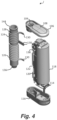
- Figure 1 shows an example of an aerosol provision device 100 for generating aerosol from an aerosol generating medium/material.
- the device 100 may be used to heat a replaceable article 110 comprising the aerosol generating medium, to generate an aerosol or other inhalable medium which is inhaled by a user of the device 100.
- the device 100 comprises a housing 102 (in the form of an outer cover) which surrounds and houses various components of the device 100.
- the device 100 has an opening 104 in one end, through which the article 110 may be inserted for heating by a heating assembly. In use, the article 110 may be fully or partially inserted into the heating assembly where it may be heated by one or more components of the heater assembly.
- the device 100 of this example comprises a first end member 106 which comprises a lid 108 which is moveable relative to the first end member 106 to close the opening 104 when no article 110 is in place.
- the lid 108 is shown in an open configuration, however the cap 108 may move into a closed configuration.
- a user may cause the lid 108 to slide in the direction of arrow "A".
- the device 100 may also include a user-operable control element 112, such as a button or switch, which operates the device 100 when pressed. For example, a user may turn on the device 100 by operating the switch 112.
- a user-operable control element 112 such as a button or switch
- the device 100 may also comprise an electrical component, such as a socket/port 114, which can receive a cable to charge a battery of the device 100.
- a socket/port 114 may be a charging port, such as a USB charging port.
- Figure 2 depicts the device 100 of Figure 1 with the outer cover 102 removed and without an article 110 present.
- the device 100 defines a longitudinal axis 134.
- the first end member 106 is arranged at one end of the device 100 and a second end member 116 is arranged at an opposite end of the device 100.
- the first and second end members 106, 116 together at least partially define end surfaces of the device 100.
- the bottom surface of the second end member 116 at least partially defines a bottom surface of the device 100.
- Edges of the outer cover 102 may also define a portion of the end surfaces.
- the lid 108 also defines a portion of a top surface of the device 100.
- the end of the device closest to the opening 104 may be known as the proximal end (or mouth end) of the device 100 because, in use, it is closest to the mouth of the user.
- a user inserts an article 110 into the opening 104, operates the user control 112 to begin heating the aerosol generating material and draws on the aerosol generated in the device. This causes the aerosol to flow through the device 100 along a flow path towards the proximal end of the device 100.
- the other end of the device furthest away from the opening 104 may be known as the distal end of the device 100 because, in use, it is the end furthest away from the mouth of the user. As a user draws on the aerosol generated in the device, the aerosol flows away from the distal end of the device 100.
- the device 100 further comprises a power source 118.
- the power source 118 may be, for example, a battery, such as a rechargeable battery or a non-rechargeable battery.
- suitable batteries include, for example, a lithium battery (such as a lithium-ion battery), a nickel battery (such as a nickel-cadmium battery), and an alkaline battery.
- the battery is electrically coupled to the heating assembly to supply electrical power when required and under control of a controller (not shown) to heat the aerosol generating material.
- the battery is connected to a central support 120 which holds the battery 118 in place.
- the device further comprises at least one electronics module 122.
- the electronics module 122 may comprise, for example, a printed circuit board (PCB).
- the PCB 122 may support at least one controller, such as a processor, and memory.
- the PCB 122 may also comprise one or more electrical tracks to electrically connect together various electronic components of the device 100.
- the battery terminals may be electrically connected to the PCB 122 so that power can be distributed throughout the device 100.
- the socket 114 may also be electrically coupled to the battery via the electrical tracks.
- the heating assembly is an inductive heating assembly and comprises various components to heat the aerosol generating material of the article 110 via an inductive heating process.
- Induction heating is a process of heating an electrically conducting object (such as a susceptor) by electromagnetic induction.
- An induction heating assembly may comprise an inductive element, for example, one or more inductor coils, and a device for passing a varying electric current, such as an alternating electric current, through the inductive element.
- the varying electric current in the inductive element produces a varying magnetic field.
- the varying magnetic field penetrates a susceptor suitably positioned with respect to the inductive element, and generates eddy currents inside the susceptor.
- the susceptor has electrical resistance to the eddy currents, and hence the flow of the eddy currents against this resistance causes the susceptor to be heated by Joule heating.
- the susceptor comprises ferromagnetic material such as iron, nickel or cobalt
- heat may also be generated by magnetic hysteresis losses in the susceptor, i.e. by the varying orientation of magnetic dipoles in the magnetic material as a result of their alignment with the varying magnetic field.
- inductive heating as compared to heating by conduction for example, heat is generated inside the susceptor, allowing for rapid heating. Further, there need not be any physical contact between the inductive heater and the susceptor, allowing for enhanced freedom in construction and application.
- first and second inductor coils 124, 126 may have at least one characteristic different from each other.
- the first inductor coil 124 may have at least one characteristic different from the second inductor coil 126.
- the first inductor coil 124 may have a different value of inductance than the second inductor coil 126.
- the first and second inductor coils 124, 126 are of different lengths such that the first inductor coil 124 is wound over a smaller section of the susceptor 132 than the second inductor coil 126.
- the first inductor coil 124 and the second inductor coil 126 are wound in opposite directions. This can be useful when the inductor coils are active at different times. For example, initially, the first inductor coil 124 may be operating to heat a first section of the article 110, and at a later time, the second inductor coil 126 may be operating to heat a second section of the article 110. Winding the coils in opposite directions helps reduce the current induced in the inactive coil when used in conjunction with a particular type of control circuit. In Figure 2 , the first inductor coil 124 is a right-hand helix and the second inductor coil 126 is a left-hand helix.
- the insulating member 128 can also fully or partially support the first and second inductor coils 124, 126.
- the first and second inductor coils 124, 126 are positioned around the insulating member 128 and are in contact with a radially outward surface of the insulating member 128.
- the insulating member 128 does not abut the first and second inductor coils 124, 126.
- a small gap may be present between the outer surface of the insulating member 128 and the inner surface of the first and second inductor coils 124, 126.
- the device 100 may comprise one or more temperature sensors, which can be used to measure the temperature of the susceptor 132.
- a temperature sensor may be affixed to the outer surface of the susceptor 132, or may be arranged in proximity to the susceptor 132.
- Each sensor may comprise one or more wires connected to the temperature sensor.
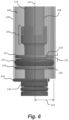
- Figure 6 depicts a first wire 208 connected to a first temperature sensor (not visible in Figure 6 ).
- the wire 208 connects the temperature sensor to other components within the device, such as the PCB 122.
- a controller arranged on the PCB 122, for example, can determine the temperature of the susceptor 132 based on signals received from the temperature sensor(s).
- the device 100 can be configured to control the one or more induction coils 124, 126 based on the detected temperature. For example, an inductor coil may be turned off when the temperature of the susceptor 132 has reached a pre-determined threshold.
- the support 136 further comprises a second portion 216, which is spaced apart from the first portion 212 along the axis 204.
- the second portion may be omitted.
- the second portion 216 may be similar to the first portion 212.
- the first and second portions 212, 216 may have a similar cross-sectional shape and/or size, and/or a similar depth.
- the second portion 216 comprises a second channel 218, through which the wire 208 is routed.
- the support 136 is hollow. Debris and/or liquid from the heated aerosol generating material may pass from the susceptor 132 and into the hollow cavity of the support 136. As mentioned in relation to Figure 3 , the device 100 may comprise a second lid 140 which can be opened to allow a user to clean the susceptor 132 and/or the support 136.
- Figure 7 shows a perspective view of the support 136 in the vicinity of the channel 210.
- the channel 210 is formed through the first portion 212, and the wire 208 passes through the channel 210.
- the channel 210 has a depth 302a measured in a direction perpendicular to the axis 204.
- the channels also have a width 302b measured in a direction perpendicular to the depth 302a. In this example, the depth 302a is about 1.3mm and the width 302b is about 0.9mm.
- the wire 208 is also surrounded by the resilient member 214, and passes through a second channel 218 formed in the second portion 216.
- the first portion 212 and the second portion 216 each comprise four channels, through which four wires 208, 308a, 308b, 308c are routed.
- the first wire 208 and the second wire 308a may be connected to a first temperature sensor
- the third wire 308b and the fourth wire 308c may be connected to a second temperature sensor, for example.
- Figure 8 shows diagrammatic representation of the support 136 of Figures 6 and 7 in a top-down view.
- the hollow, cylindrical susceptor 132 is shown engaged with the engagement region 202 of the support 136.
- the outer perimeter of the resilient member 214 extends further away from the axis 204 than the outer perimeter of the first portion 212, measured in a radial direction 304.
- the resilient member 214 can therefore abut the inner surface of the insulating member, when present.
- the device 100 comprises a hollow insulating member 128 which surrounds the susceptor 132.
- a space 406 (such as an air gap) is provided between the outer surface of the susceptor 132 and the inner surface of the insulating member 128.
- the device 100 comprises temperature sensor 424 which is affixed to an outer surface of the susceptor 132.
- a wire 408 is connected to the temperature sensor 424.
- One or more other wires may also be connected to the temperature sensor 424.
- the support 436 further comprises an end portion 420 which abuts the distal end of the insulating member 128.
- the end portion 420 supports and holds the insulating member 128 in place, while also helping further seal the space 406 between the susceptor 132 and the insulating member 128.
- the end portion 420 also defines a channel 426, in the form of a through hole, through which the wire 408 is routed. This allows the wire 408 to be connected to other components of the device 100.
- the first portion, the second portion, the susceptor and the insulating member each have a substantially circular shape cross section.
- the cross sections of any or all of these components may take any other shape, such as square, rectangular or elliptical.
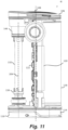
- Figure 11 depicts part of the device 100.
- the inductor coils 124, 126 and insulating member 128 have been omitted for clarity.
- the first support 136 defines an axis 204 which is arranged parallel to the longitudinal axis 158 of the susceptor 132, and it may also be arranged parallel to the longitudinal axis 134 of the device 100.
- the axis 204 may be the longitudinal axis of the support 136, for example.
- the first engagement region 202 may comprise two or more protrusions 224 or prongs which extend from an end of the first support 136 along the susceptor 132 in the direction of the axis 204.
- Each of the protrusions 224 are spaced around the outer surface of the susceptor 132 and are separated by a gap. These protrusions 224 flex outwards as the susceptor 132 is inserted into the first engagement region 202.
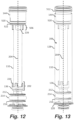
- the second support 144 comprises a second engagement region 506 at one end, which receives and engages a proximal end of the susceptor 132.
- the proximal end of the susceptor 132 is the end of the susceptor 132 that is arranged closest to a user's mouth when the device 100 is in use.
- the susceptor 132 and second engagement region 506 form an interference fit or friction fit, however other attachment means may be used.
- the second engagement region 506 may also comprise two or more protrusions 226 or prongs which extend from an end of the second support 144 along the susceptor 132 in the direction of the axis 204. Each of the protrusions 226 are spaced around the outer surface of the susceptor 132 and are separated by a gap. The protrusions 226 allow the second support 144 to flex as the susceptor 132 is inserted into the engagement region 506.
- the first and second supports 134, 144 may be made from the same, or different material.
- the first and second supports 134, 144 are both made from a plastics material, such as PEEK which a thermal conductivity of about 0.32W/mK and a melting point of about 343°C. With a low thermal conductivity, the rate at which heat flows from the susceptor 132 through the first and second supports 134, 144 is reduced. Other materials with low thermal conductivities may be used instead.
- the first and second supports 134, 144 are made from plastics materials because these can be lightweight.
- the susceptor 132 is heated by the first and second inductor coils 124, 126 to a temperature of between about 240°C and about 280°C.
- the first and second supports 134, 144 having a melting point which is greater than the temperature of the heated susceptor 132 by at least 60°C, the first and second supports 134, 144 are less likely to soften and weaken due to the heat.
- Figure 13 shows the arrangement of Figure 12 with an insulating member 128 surrounding the susceptor 132.
- the insulating member 128 is depicted as being transparent so that the susceptor 132 is visible within the hollow insulating member 128.
- the insulating member 128 may or may not be transparent.
- the insulating member 128 is positioned away from the susceptor 132 to provide an air gap 206 between the outer surface of the susceptor 132 and the inner surface of the insulating member 128.
- the air gap 206 provides insulation.
- the insulating member 128 may be held in place by one or more components of the device 100. In the present example, however, the insulating member 128 abuts the first support 136 towards one end of the insulating member.
- the first support 136 may comprise an end portion 220 which has a cross section that is larger than a cross section of the insulating member 128. A first end of the insulating member 128 therefore abuts the end portion 220 of the first support 136.
- the insulating member 128 can be held substantially parallel to the axis 204.
- the insulating member 128 also abuts the second support 144 towards an end of the insulating member 128.
- the second support 144 may also comprise an end portion 512 which has a cross section that is larger than a cross section of the insulating member 128. A second end of the insulating member 128 may therefore abut the end portion 512 of the second support 144.
- Figure 13 shows a small gap between the end portion 512 of the second support 144 and the second end of the insulating member 128. The small gap can allow for manufacturing tolerances and may not be present in certain examples.
- Figures 12 and 13 show the first support 136 with a first resilient member 214 extending around a portion of the support 136.
- the first resilient member 214 is an O-ring.
- Figure 13 shows that the first resilient member 214 is dimensioned such that it abuts an inner surface of the insulating member 128 when the insulating member 128 is in place.
- the first resilient member 214 can therefore help seal the space 208 between the susceptor 132 and insulating member 128 to better insulate the device 100.
- the first resilient member 214 may be compressed when the insulating member 128 surrounds the susceptor 132.
- the first support 132 comprises a first portion 212 and a second portion 216, where the first resilient member 214 is arranged between the first and second portions 212, 216.
- the first and second portions 212, 216 stop the first resilient member 214 from sliding along the first support 136, which could reduce the sealing effect.
- the second support 144 comprises a recess 522 within which the second resilient member is located.
- the second resilient member 520 has a width that is smaller than a width of the first resilient member 214. The widths of the resilient members are measured in a direction perpendicular to the axis 204.
- the first and second resilient members 214, 520 are made from a material which has a thermal conductivity of less than about 0.5W/mK, such as less than about 0.25W/mK.
- the first and second resilient members 214, 520 may be made from silicone rubber, for example.
Landscapes
- Physics & Mathematics (AREA)
- Electromagnetism (AREA)
- Resistance Heating (AREA)
Applications Claiming Priority (4)
| Application Number | Priority Date | Filing Date | Title |
|---|---|---|---|
| US201962816303P | 2019-03-11 | 2019-03-11 | |
| US201962816337P | 2019-03-11 | 2019-03-11 | |
| EP20714125.0A EP3937678B1 (fr) | 2019-03-11 | 2020-03-09 | Dispositif générateur d'aérosol |
| PCT/EP2020/056233 WO2020182743A1 (fr) | 2019-03-11 | 2020-03-09 | Dispositif de fourniture d'aérosol |
Related Parent Applications (2)
| Application Number | Title | Priority Date | Filing Date |
|---|---|---|---|
| EP20714125.0A Division EP3937678B1 (fr) | 2019-03-11 | 2020-03-09 | Dispositif générateur d'aérosol |
| EP20714125.0A Division-Into EP3937678B1 (fr) | 2019-03-11 | 2020-03-09 | Dispositif générateur d'aérosol |
Publications (2)
| Publication Number | Publication Date |
|---|---|
| EP4581965A2 true EP4581965A2 (fr) | 2025-07-09 |
| EP4581965A3 EP4581965A3 (fr) | 2025-09-10 |
Family
ID=70005583
Family Applications (2)
| Application Number | Title | Priority Date | Filing Date |
|---|---|---|---|
| EP20714125.0A Active EP3937678B1 (fr) | 2019-03-11 | 2020-03-09 | Dispositif générateur d'aérosol |
| EP25178635.6A Pending EP4581965A3 (fr) | 2019-03-11 | 2020-03-09 | Dispositif de fourniture d'aérosol |
Family Applications Before (1)
| Application Number | Title | Priority Date | Filing Date |
|---|---|---|---|
| EP20714125.0A Active EP3937678B1 (fr) | 2019-03-11 | 2020-03-09 | Dispositif générateur d'aérosol |
Country Status (7)
| Country | Link |
|---|---|
| US (2) | US12239165B2 (fr) |
| EP (2) | EP3937678B1 (fr) |
| JP (3) | JP7296471B2 (fr) |
| KR (1) | KR20210130740A (fr) |
| PL (1) | PL3937678T3 (fr) |
| TW (1) | TW202038773A (fr) |
| WO (1) | WO2020182743A1 (fr) |
Families Citing this family (19)
| Publication number | Priority date | Publication date | Assignee | Title |
|---|---|---|---|---|
| GB201903251D0 (en) * | 2019-03-11 | 2019-04-24 | Nicoventures Trading Ltd | Aerosol provision device |
| CN114072016B (zh) * | 2019-07-04 | 2026-01-13 | 菲利普莫里斯生产公司 | 包括包含具有相同谐振频率的第一lc电路和第二lc电路的感应加热装置的气溶胶生成装置 |
| TW202215996A (zh) * | 2020-10-16 | 2022-05-01 | 瑞士商傑太日煙國際股份有限公司 | 帶有蓋和隔絕氣隙之氣溶膠產生裝置 |
| PL4252568T3 (pl) * | 2020-12-11 | 2025-06-30 | Japan Tobacco Inc. | Inhalator aromatu |
| PL4260735T3 (pl) * | 2020-12-11 | 2026-04-27 | Japan Tobacco Inc. | Inhalator substancji smakowo-zapachowej i sposób wytwarzania inhalatora substancji smakowo-zapachowej |
| GB202020424D0 (en) * | 2020-12-22 | 2021-02-03 | Nicoventures Trading Ltd | Inductor coil |
| TW202235018A (zh) * | 2021-02-02 | 2022-09-16 | 瑞士商傑太日煙國際股份有限公司 | 用於氣溶膠產生裝置之感應加熱組件 |
| US20240090578A1 (en) * | 2021-02-02 | 2024-03-21 | Jt International Sa | Aerosol Generating Device |
| TW202231200A (zh) * | 2021-02-02 | 2022-08-16 | 瑞士商傑太日煙國際股份有限公司 | 用於氣溶膠產生裝置之感應加熱組件 |
| KR102554954B1 (ko) * | 2021-07-21 | 2023-07-12 | 주식회사 케이티앤지 | 에어로졸 생성 장치 |
| GB202114494D0 (en) * | 2021-10-11 | 2021-11-24 | Nicoventures Trading Ltd | Aerosol provision device |
| EP4312613A4 (fr) * | 2021-11-11 | 2024-10-16 | KT&G Corporation | Dispositif de génération d'aérosol avec support fournissant de l'air à un article de génération d'aérosol |
| WO2023118212A1 (fr) * | 2021-12-20 | 2023-06-29 | Nicoventures Trading Limited | Appareil pour chauffer un matériau générateur d'aérosol |
| WO2024004049A1 (fr) * | 2022-06-28 | 2024-01-04 | 日本たばこ産業株式会社 | Dispositif de génération d'aérosol |
| CN115624210B (zh) * | 2022-09-21 | 2026-01-20 | 深圳麦时科技有限公司 | 气溶胶产生装置及其加热组件 |
| GB202214425D0 (en) * | 2022-09-30 | 2022-11-16 | Nicoventures Trading Ltd | Aerosol provision device |
| CN120265167A (zh) * | 2023-02-22 | 2025-07-04 | 韩国烟草人参公社 | 气溶胶生成装置用加热器组装体以及包括其的气溶胶生成装置 |
| CN222583655U (zh) * | 2024-04-30 | 2025-03-11 | 尼科创业贸易有限公司 | 用于气溶胶供应装置的加热组件、气溶胶供应装置及系统 |
| EP4681559A1 (fr) * | 2024-07-19 | 2026-01-21 | Nicoventures Trading Limited | Dispositif de fourniture d'aérosol |
Family Cites Families (43)
| Publication number | Priority date | Publication date | Assignee | Title |
|---|---|---|---|---|
| US5870524A (en) | 1997-01-24 | 1999-02-09 | Swiatosz; Edmund | Smoke generator method and apparatus |
| EP2201850A1 (fr) | 2008-12-24 | 2010-06-30 | Philip Morris Products S.A. | Article incluant des informations d'identification à utiliser dans un système de fumée chauffé thermiquement |
| JP5368393B2 (ja) | 2010-08-05 | 2013-12-18 | 東京エレクトロン株式会社 | 気化装置、基板処理装置及び塗布現像装置 |
| SG11201507630SA (en) | 2013-03-15 | 2015-10-29 | Philip Morris Products Sa | Aerosol-generating device comprising multiple solid-liquid phase-change materials |
| NZ718007A (en) | 2013-10-29 | 2017-06-30 | British American Tobacco Investments Ltd | Apparatus for heating smokable material |
| ES2703350T5 (es) * | 2014-05-12 | 2024-07-10 | Philip Morris Products Sa | Dispositivo vaporizador mejorado |
| TWI666993B (zh) * | 2014-05-21 | 2019-08-01 | Philip Morris Products S. A. | 用於霧劑產生之感應加熱裝置及系統 |
| TWI667964B (zh) * | 2014-05-21 | 2019-08-11 | 瑞士商菲利浦莫里斯製品股份有限公司 | 用於霧劑產生之感應型加熱裝置及系統 |
| PT2996504T (pt) | 2014-05-21 | 2017-01-02 | Philip Morris Products Sa | Artigo gerador de aerossol tendo um susceptor de multimaterial |
| GB2527597B (en) * | 2014-06-27 | 2016-11-23 | Relco Induction Dev Ltd | Electronic Vapour Inhalers |
| GB2533080B (en) | 2014-11-11 | 2017-08-02 | Jt Int Sa | Electronic vapour inhalers |
| CN108601397A (zh) * | 2015-08-17 | 2018-09-28 | 菲利普莫里斯生产公司 | 气溶胶生成系统和用于这类系统的气溶胶生成制品 |
| AU2016310219A1 (en) | 2015-08-17 | 2017-11-30 | Philip Morris Products S.A. | Aerosol-generating system and aerosol-generating article for use in such a system |
| US20170055583A1 (en) | 2015-08-31 | 2017-03-02 | British American Tobacco (Investments) Limited | Apparatus for heating smokable material |
| US20170055580A1 (en) * | 2015-08-31 | 2017-03-02 | British American Tobacco (Investments) Limited | Apparatus for heating smokable material |
| US10918134B2 (en) * | 2015-10-21 | 2021-02-16 | Rai Strategic Holdings, Inc. | Power supply for an aerosol delivery device |
| RU2738700C2 (ru) | 2015-10-22 | 2020-12-15 | Филип Моррис Продактс С.А. | Изделие, генерирующее аэрозоль, и способ изготовления такого изделия, генерирующего аэрозоль, устройство и система, генерирующие аэрозоль |
| US20170119046A1 (en) * | 2015-10-30 | 2017-05-04 | British American Tobacco (Investments) Limited | Apparatus for Heating Smokable Material |
| WO2017118553A1 (fr) * | 2016-01-07 | 2017-07-13 | Philip Morris Products S.A. | Dispositif générateur d'aérosol comportant un compartiment étanché |
| CA3007911A1 (fr) | 2016-02-12 | 2017-08-17 | Philip Morris Products S.A. | Systeme de production d'aerosol avec detecteur de bouffee |
| CN108697168A (zh) * | 2016-03-02 | 2018-10-23 | 菲利普莫里斯生产公司 | 包括反馈装置的气溶胶生成装置 |
| GB201605102D0 (en) * | 2016-03-24 | 2016-05-11 | Nicoventures Holdings Ltd | Mechanical connector for electronic vapour provision system |
| US10028534B2 (en) * | 2016-04-20 | 2018-07-24 | Rai Strategic Holdings, Inc. | Aerosol delivery device, and associated apparatus and method of formation thereof |
| US10231485B2 (en) * | 2016-07-08 | 2019-03-19 | Rai Strategic Holdings, Inc. | Radio frequency to direct current converter for an aerosol delivery device |
| RU2743742C2 (ru) * | 2016-08-31 | 2021-02-25 | Филип Моррис Продактс С.А. | Устройство, генерирующее аэрозоль, с индуктором |
| CN207236078U (zh) * | 2016-09-06 | 2018-04-17 | 深圳市合元科技有限公司 | 烟雾发生装置 |
| CA3030203A1 (fr) * | 2016-09-14 | 2018-03-22 | Philip Morris Products S.A. | Systeme de generation d'aerosol et son procede de commande |
| KR102597493B1 (ko) * | 2016-10-19 | 2023-11-02 | 니코벤처스 트레이딩 리미티드 | 유도 가열 배열체 |
| US10674768B2 (en) | 2017-01-06 | 2020-06-09 | Charles S Stoner | Induction vaporizer and method |
| EP3589146B1 (fr) * | 2017-02-28 | 2023-04-05 | Philip Morris Products S.A. | Dispositif de génération d'aérosol comprenant un actuateur de-agglomération |
| GB201705259D0 (en) | 2017-03-31 | 2017-05-17 | British American Tobacco Investments Ltd | Induction coil arrangement |
| US11433193B2 (en) * | 2017-05-18 | 2022-09-06 | Jt International S.A. | Device for heating a vapour forming substance such as tobacco |
| KR102569256B1 (ko) * | 2017-08-09 | 2023-08-22 | 필립모리스 프로덕츠 에스.에이. | 감소된 분리를 갖는 인덕터 코일을 갖는 에어로졸 발생 장치 |
| CN111031821A (zh) | 2017-08-09 | 2020-04-17 | 菲利普莫里斯生产公司 | 具有可拆卸插入的加热室的气溶胶生成装置 |
| WO2019030172A1 (fr) * | 2017-08-09 | 2019-02-14 | Philip Morris Products S.A. | Dispositif de génération d'aérosol comprenant un dispositif de chauffage par induction et des composants mobiles |
| KR102500901B1 (ko) * | 2017-08-09 | 2023-02-17 | 필립모리스 프로덕츠 에스.에이. | 제거 가능한 서셉터를 갖는 에어로졸 발생 장치 |
| JP7235721B2 (ja) * | 2017-08-09 | 2023-03-08 | フィリップ・モーリス・プロダクツ・ソシエテ・アノニム | 非円形のインダクタコイルを備えたエアロゾル発生システム |
| CN208286365U (zh) | 2017-10-13 | 2018-12-28 | 惠州市吉瑞科技有限公司深圳分公司 | 一种雾化系统以及烟杆 |
| GB201722183D0 (en) * | 2017-12-28 | 2018-02-14 | British American Tobacco Investments Ltd | Apparatus for heating aerosolisable material |
| US10750787B2 (en) * | 2018-01-03 | 2020-08-25 | Cqens Technologies Inc. | Heat-not-burn device and method |
| CN208016042U (zh) * | 2018-03-28 | 2018-10-26 | 深圳市新宜康科技股份有限公司 | 基于上出芯式电磁感应加热不燃烧装置 |
| CN208228311U (zh) * | 2018-04-10 | 2018-12-14 | 深圳市新宜康科技股份有限公司 | 高能量利用率的加热不燃烧装置 |
| WO2020023547A1 (fr) * | 2018-07-23 | 2020-01-30 | Wellness Insight Technologies, Inc. | Système d'analyse et de commande d'informations de dosage de milieu consommable |
-
2020
- 2020-03-09 US US17/593,147 patent/US12239165B2/en active Active
- 2020-03-09 TW TW109107620A patent/TW202038773A/zh unknown
- 2020-03-09 WO PCT/EP2020/056233 patent/WO2020182743A1/fr not_active Ceased
- 2020-03-09 JP JP2021554586A patent/JP7296471B2/ja active Active
- 2020-03-09 PL PL20714125.0T patent/PL3937678T3/pl unknown
- 2020-03-09 EP EP20714125.0A patent/EP3937678B1/fr active Active
- 2020-03-09 EP EP25178635.6A patent/EP4581965A3/fr active Pending
- 2020-03-09 KR KR1020217028542A patent/KR20210130740A/ko active Pending
-
2023
- 2023-06-09 JP JP2023095356A patent/JP7573070B2/ja active Active
-
2024
- 2024-10-11 JP JP2024178562A patent/JP7834826B2/ja active Active
- 2024-10-15 US US18/916,367 patent/US20250031763A1/en active Pending
Also Published As
| Publication number | Publication date |
|---|---|
| PL3937678T3 (pl) | 2025-09-08 |
| KR20210130740A (ko) | 2021-11-01 |
| US20220183372A1 (en) | 2022-06-16 |
| US20250031763A1 (en) | 2025-01-30 |
| TW202038773A (zh) | 2020-11-01 |
| EP4581965A3 (fr) | 2025-09-10 |
| US12239165B2 (en) | 2025-03-04 |
| EP3937678B1 (fr) | 2025-07-02 |
| JP7834826B2 (ja) | 2026-03-24 |
| JP2025001045A (ja) | 2025-01-07 |
| JP2022524410A (ja) | 2022-05-02 |
| JP7573070B2 (ja) | 2024-10-24 |
| JP7296471B2 (ja) | 2023-06-22 |
| EP3937678A1 (fr) | 2022-01-19 |
| JP2023113901A (ja) | 2023-08-16 |
| WO2020182743A1 (fr) | 2020-09-17 |
Similar Documents
| Publication | Publication Date | Title |
|---|---|---|
| EP3937678B1 (fr) | Dispositif générateur d'aérosol | |
| AU2023229474A1 (en) | Aerosol provision device | |
| EP3937701B1 (fr) | Dispositif de fourniture d'aérosol | |
| EP4445779A1 (fr) | Dispositif de fourniture d'aérosol | |
| US20230354903A1 (en) | Aerosol provision device | |
| JP2025128382A (ja) | エアロゾル供給デバイス | |
| EP4213658A1 (fr) | Dispositif de fourniture d'aérosol |
Legal Events
| Date | Code | Title | Description |
|---|---|---|---|
| PUAI | Public reference made under article 153(3) epc to a published international application that has entered the european phase |
Free format text: ORIGINAL CODE: 0009012 |
|
| STAA | Information on the status of an ep patent application or granted ep patent |
Free format text: STATUS: THE APPLICATION HAS BEEN PUBLISHED |
|
| AC | Divisional application: reference to earlier application |
Ref document number: 3937678 Country of ref document: EP Kind code of ref document: P |
|
| AK | Designated contracting states |
Kind code of ref document: A2 Designated state(s): AL AT BE BG CH CY CZ DE DK EE ES FI FR GB GR HR HU IE IS IT LI LT LU LV MC MK MT NL NO PL PT RO RS SE SI SK SM TR |
|
| REG | Reference to a national code |
Ref country code: DE Ref legal event code: R079 Free format text: PREVIOUS MAIN CLASS: A24F0040510000 Ipc: A24F0040200000 |
|
| PUAL | Search report despatched |
Free format text: ORIGINAL CODE: 0009013 |
|
| AK | Designated contracting states |
Kind code of ref document: A3 Designated state(s): AL AT BE BG CH CY CZ DE DK EE ES FI FR GB GR HR HU IE IS IT LI LT LU LV MC MK MT NL NO PL PT RO RS SE SI SK SM TR |
|
| RIC1 | Information provided on ipc code assigned before grant |
Ipc: A24F 40/20 20200101AFI20250804BHEP Ipc: A24F 40/465 20200101ALI20250804BHEP Ipc: A24F 40/51 20200101ALI20250804BHEP |
|
| STAA | Information on the status of an ep patent application or granted ep patent |
Free format text: STATUS: REQUEST FOR EXAMINATION WAS MADE |
|
| P01 | Opt-out of the competence of the unified patent court (upc) registered |
Free format text: CASE NUMBER: UPC_APP_0005746_4581965/2026 Effective date: 20260217 |
|
| 17P | Request for examination filed |
Effective date: 20260310 |