EP4581966A1 - Non-nicotine dispositif de génération d'aérosol avec détection de niveau et arret automatique - Google Patents
Non-nicotine dispositif de génération d'aérosol avec détection de niveau et arret automatique Download PDFInfo
- Publication number
- EP4581966A1 EP4581966A1 EP25155690.8A EP25155690A EP4581966A1 EP 4581966 A1 EP4581966 A1 EP 4581966A1 EP 25155690 A EP25155690 A EP 25155690A EP 4581966 A1 EP4581966 A1 EP 4581966A1
- Authority
- EP
- European Patent Office
- Prior art keywords
- nicotine
- vapor formulation
- pod assembly
- reservoir
- controller
- Prior art date
- Legal status (The legal status is an assumption and is not a legal conclusion. Google has not performed a legal analysis and makes no representation as to the accuracy of the status listed.)
- Pending
Links
Images


Classifications
-
- A—HUMAN NECESSITIES
- A24—TOBACCO; CIGARS; CIGARETTES; SIMULATED SMOKING DEVICES; SMOKERS' REQUISITES
- A24F—SMOKERS' REQUISITES; MATCH BOXES; SIMULATED SMOKING DEVICES
- A24F40/00—Electrically operated smoking devices; Component parts thereof; Manufacture thereof; Maintenance or testing thereof; Charging means specially adapted therefor
- A24F40/50—Control or monitoring
- A24F40/53—Monitoring, e.g. fault detection
-
- A—HUMAN NECESSITIES
- A24—TOBACCO; CIGARS; CIGARETTES; SIMULATED SMOKING DEVICES; SMOKERS' REQUISITES
- A24F—SMOKERS' REQUISITES; MATCH BOXES; SIMULATED SMOKING DEVICES
- A24F40/00—Electrically operated smoking devices; Component parts thereof; Manufacture thereof; Maintenance or testing thereof; Charging means specially adapted therefor
- A24F40/40—Constructional details, e.g. connection of cartridges and battery parts
- A24F40/42—Cartridges or containers for inhalable precursors
-
- A—HUMAN NECESSITIES
- A24—TOBACCO; CIGARS; CIGARETTES; SIMULATED SMOKING DEVICES; SMOKERS' REQUISITES
- A24F—SMOKERS' REQUISITES; MATCH BOXES; SIMULATED SMOKING DEVICES
- A24F40/00—Electrically operated smoking devices; Component parts thereof; Manufacture thereof; Maintenance or testing thereof; Charging means specially adapted therefor
- A24F40/50—Control or monitoring
-
- A—HUMAN NECESSITIES
- A24—TOBACCO; CIGARS; CIGARETTES; SIMULATED SMOKING DEVICES; SMOKERS' REQUISITES
- A24F—SMOKERS' REQUISITES; MATCH BOXES; SIMULATED SMOKING DEVICES
- A24F40/00—Electrically operated smoking devices; Component parts thereof; Manufacture thereof; Maintenance or testing thereof; Charging means specially adapted therefor
- A24F40/60—Devices with integrated user interfaces
-
- A—HUMAN NECESSITIES
- A61—MEDICAL OR VETERINARY SCIENCE; HYGIENE
- A61M—DEVICES FOR INTRODUCING MEDIA INTO, OR ONTO, THE BODY; DEVICES FOR TRANSDUCING BODY MEDIA OR FOR TAKING MEDIA FROM THE BODY; DEVICES FOR PRODUCING OR ENDING SLEEP OR STUPOR
- A61M15/00—Inhalators
- A61M15/06—Inhaling appliances shaped like cigars, cigarettes or pipes
-
- A—HUMAN NECESSITIES
- A24—TOBACCO; CIGARS; CIGARETTES; SIMULATED SMOKING DEVICES; SMOKERS' REQUISITES
- A24F—SMOKERS' REQUISITES; MATCH BOXES; SIMULATED SMOKING DEVICES
- A24F40/00—Electrically operated smoking devices; Component parts thereof; Manufacture thereof; Maintenance or testing thereof; Charging means specially adapted therefor
- A24F40/10—Devices using liquid inhalable precursors
-
- A—HUMAN NECESSITIES
- A61—MEDICAL OR VETERINARY SCIENCE; HYGIENE
- A61M—DEVICES FOR INTRODUCING MEDIA INTO, OR ONTO, THE BODY; DEVICES FOR TRANSDUCING BODY MEDIA OR FOR TAKING MEDIA FROM THE BODY; DEVICES FOR PRODUCING OR ENDING SLEEP OR STUPOR
- A61M2205/00—General characteristics of the apparatus
- A61M2205/36—General characteristics of the apparatus related to heating or cooling
- A61M2205/3653—General characteristics of the apparatus related to heating or cooling by Joule effect, i.e. electric resistance
-
- A—HUMAN NECESSITIES
- A61—MEDICAL OR VETERINARY SCIENCE; HYGIENE
- A61M—DEVICES FOR INTRODUCING MEDIA INTO, OR ONTO, THE BODY; DEVICES FOR TRANSDUCING BODY MEDIA OR FOR TAKING MEDIA FROM THE BODY; DEVICES FOR PRODUCING OR ENDING SLEEP OR STUPOR
- A61M2205/00—General characteristics of the apparatus
- A61M2205/50—General characteristics of the apparatus with microprocessors or computers
- A61M2205/52—General characteristics of the apparatus with microprocessors or computers with memories providing a history of measured variating parameters of apparatus or patient
-
- A—HUMAN NECESSITIES
- A61—MEDICAL OR VETERINARY SCIENCE; HYGIENE
- A61M—DEVICES FOR INTRODUCING MEDIA INTO, OR ONTO, THE BODY; DEVICES FOR TRANSDUCING BODY MEDIA OR FOR TAKING MEDIA FROM THE BODY; DEVICES FOR PRODUCING OR ENDING SLEEP OR STUPOR
- A61M2205/00—General characteristics of the apparatus
- A61M2205/82—Internal energy supply devices
- A61M2205/8206—Internal energy supply devices battery-operated
Definitions
- One or more example embodiments relate to non-nicotine electronic vaping (non-nicotine e-vaping) devices.
- Non-nicotine electronic vaping devices include a heater that vaporizes non-nicotine pre-vapor formulation material to produce non-nicotine vapor.
- a non-nicotine e-vaping device may include several non-nicotine e-vaping elements including a power source, a non-nicotine cartridge or non-nicotine e-vaping tank including the heater and a non-nicotine reservoir capable of holding the non-nicotine pre-vapor formulation material.
- At least one example embodiment provides a non-nicotine electronic vaping device comprising a non-nicotine pod assembly and a device assembly configured to engage with the non-nicotine pod assembly.
- the non-nicotine pod assembly includes: a memory storing a non-nicotine pre-vapor formulation vaporization parameter and an aggregate amount of vaporized non-nicotine pre-vapor formulation; a non-nicotine reservoir to hold non-nicotine pre-vapor formulation; and a heater configured to vaporize non-nicotine pre-vapor formulation drawn from the non-nicotine reservoir.
- the device assembly includes a controller, which is configured to: estimate an amount of non-nicotine pre-vapor formulation vaporized during a puff event based on the non-nicotine pre-vapor formulation vaporization parameter obtained from the memory and an aggregate amount of power applied to the heater during the puff event; determine an updated aggregate amount of vaporized non-nicotine pre-vapor formulation based on the aggregate amount of vaporized non-nicotine pre-vapor formulation stored in the memory and the amount of non-nicotine pre-vapor formulation vaporized during the puff event; determine that the updated aggregate amount of vaporized non-nicotine pre-vapor formulation is greater than or equal to at least one non-nicotine pre-vapor formulation level threshold; and control the non-nicotine electronic vaping device to output an indication of a current level of the non-nicotine pre-vapor formulation in the non-nicotine reservoir in response to determining that the updated aggregate amount of vaporized non-nicotine pre-vapor formulation is greater than or equal to the at least one non-nicotine pre-vapor formulation
- At least one other example embodiment provides a non-nicotine electronic vaping device comprising a non-nicotine pod assembly and a device assembly configured to engage with the non-nicotine pod assembly.
- the non-nicotine pod assembly includes: a non-nicotine reservoir to hold non-nicotine pre-vapor formulation; a heater configured to vaporize non-nicotine pre-vapor formulation drawn from the non-nicotine reservoir; and a memory storing a non-nicotine pre-vapor formulation vaporization parameter and an aggregate amount of non-nicotine pre-vapor formulation drawn from the non-nicotine reservoir.
- At least one other example embodiment provides a method of controlling a non-nicotine electronic vaping device including a non-nicotine reservoir to hold non-nicotine pre-vapor formulation and a heater configured to vaporize non-nicotine pre-vapor formulation drawn from the non-nicotine reservoir, the method comprising: estimating an amount of non-nicotine pre-vapor formulation vaporized by the heater during a puff event based on a non-nicotine pre-vapor formulation vaporization parameter and an aggregate amount of power applied to the heater during the puff event; determining an updated aggregate amount of vaporized non-nicotine pre-vapor formulation based on an aggregate amount of vaporized non-nicotine pre-vapor formulation stored in a memory and the amount of non-nicotine pre-vapor formulation vaporized during the puff event; determining that the updated aggregate amount of vaporized non-nicotine pre-vapor formulation is greater than or equal to at least one non-nicotine pre-vapor formulation level threshold; and outputting an indication of a current level of the non-nic
- At least one other example embodiment provides a method of controlling a non-nicotine electronic vaping device including a non-nicotine reservoir to hold non-nicotine pre-vapor formulation and a heater configured to vaporize non-nicotine pre-vapor formulation drawn from the non-nicotine reservoir, the method comprising: estimating an amount of non-nicotine pre-vapor formulation drawn from the non-nicotine reservoir during a puff event based on a non-nicotine pre-vapor formulation vaporization parameter and an aggregate amount of power applied to the heater during the puff event; determining an updated aggregate amount of non-nicotine pre-vapor formulation drawn from the non-nicotine reservoir based on an aggregate amount of non-nicotine pre-vapor formulation drawn from the non-nicotine reservoir stored in a memory and the amount of non-nicotine pre-vapor formulation drawn from the non-nicotine reservoir during the puff event; determining that the updated aggregate amount of non-nicotine pre-vapor formulation drawn from the non-nicotine reservoir is greater than or equal to at least one
- At least one other example embodiment provides a method of controlling a non-nicotine electronic vaping device including a non-nicotine pod assembly and a device assembly, the method comprising: obtaining an empty flag from a memory in the non-nicotine pod assembly inserted into the device assembly, the empty flag indicating that non-nicotine pre-vapor formulation in the non-nicotine pod assembly is depleted; and disabling vaping at the non-nicotine electronic vaping device based on the empty flag obtained from the memory.
- first, second, third, etc. may be used herein to describe various elements, regions, layers and/or sections, these elements, regions, layers, and/or sections should not be limited by these terms. These terms are only used to distinguish one element, region, layer, or section from another region, layer, or section. Thus, a first element, region, layer, or section discussed below could be termed a second element, region, layer, or section without departing from the teachings of example embodiments.
- spatially relative terms e.g., "beneath,” “below,” “lower,” “above,” “upper,” and the like
- the spatially relative terms are intended to encompass different orientations of the device in use or operation in addition to the orientation depicted in the figures. For example, if the device in the figures is turned over, elements described as “below” or “beneath” other elements or features would then be oriented “above” the other elements or features. Thus, the term “below” may encompass both an orientation of above and below.
- the device may be otherwise oriented (rotated 90 degrees or at other orientations) and the spatially relative descriptors used herein interpreted accordingly.
- Hardware may be implemented using processing or control circuitry such as, but not limited to, one or more processors, one or more Central Processing Units (CPUs), one or more microcontrollers, one or more arithmetic logic units (ALUs), one or more digital signal processors (DSPs), one or more microcomputers, one or more field programmable gate arrays (FPGAs), one or more System-on-Chips (SoCs), one or more programmable logic units (PLUs), one or more microprocessors, one or more Application Specific Integrated Circuits (ASICs), or any other device or devices capable of responding to and executing instructions in a defined manner.
- processors such as, but not limited to, one or more processors, one or more Central Processing Units (CPUs), one or more microcontrollers, one or more arithmetic logic units (ALUs), one or more digital signal processors (DSPs), one or more microcomputers, one or more field programmable gate arrays (FPGAs), one or more System-
- non-nicotine electronic vaping device or “non-nicotine e-vaping device” as used herein may be referred to on occasion using, and considered synonymous with, non-nicotine e-vapor apparatus and/or non-nicotine e-vaping apparatus.
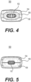
- FIG. 1 is a front view of a non-nicotine e-vaping device according to an example embodiment.
- FIG. 2 is a side view of the non-nicotine e-vaping device of FIG. 1 .
- FIG. 3 is a rear view of the non-nicotine e-vaping device of FIG. 1 .
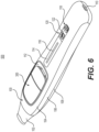
- a non-nicotine e-vaping device 500 includes a device body 100 that is configured to receive a non-nicotine pod assembly 300.
- the non-nicotine pod assembly 300 is a modular article configured to hold a non-nicotine pre-vapor formulation.
- a "non-nicotine pre-vapor formulation" is a material or combination of materials that may be transformed into a vapor.
- the non-nicotine pre-vapor formulation may be a liquid, solid, and/or gel formulation including, but not limited to, water, beads, solvents, active ingredients, ethanol, plant extracts, natural or artificial flavors, and/or vapor formers such as glycerin and propylene glycol.
- the non-nicotine pre-vapor formulation neither includes tobacco nor is derived from tobacco.
- a non-nicotine compound of the non-nicotine pre-vapor formulation may be part of, or included in a liquid or a partial-liquid that includes an extract, an oil, an alcohol, a tincture, a suspension, a dispersion, a colloid, a general non-neutral (slightly acidic or slightly basic) solution, or combinations thereof.
- the non-nicotine compound may be infused into, comingled, or otherwise combined with the other ingredients of the non-nicotine pre-vapor formulation.
- the non-nicotine compound undergoes a slow, natural decarboxylation process over an extended duration of time at relatively low temperatures, including at or below room temperature (e.g., 72 °F).
- the non-nicotine compound may undergo a significantly elevated decarboxylation process (e.g., 50% decarboxylation or greater) if exposed to elevated temperatures, especially in the range of about 175 °F or greater over a period of time (minutes or hours) at a relatively low pressure such as 1 atmosphere.
- the non-nicotine compound may be from a medicinal plant (e.g., a naturally-occurring constituent of a plant that provides a medically-accepted therapeutic effect).
- the medicinal plant may be a cannabis plant, and the constituent may be at least one cannabis-derived constituent.
- Cannabinoids e.g., phytocannabinoids
- terpenes are examples of cannabis-derived constituents.
- Cannabinoids interact with receptors in the body to produce a wide range of effects. As a result, cannabinoids have been used for a variety of medicinal purposes.
- Cannabis-derived materials may include the leaf and/or flower material from one or more species of cannabis plants, or extracts from the one or more species of cannabis plants.
- the one or more species of cannabis plants may include Cannabis sativa, Cannabis indica, and Cannabis ruderalis.
- the non-nicotine pre-vapor formulation includes a mixture of cannabis and/or cannabis-derived constituents that are, or are derived from, 60-80% (e.g., 70%) Cannabis sativa and 20-40% (e.g., 30%) Cannabis indica.
- Non-limiting examples of cannabis-derived cannabinoids include tetrahydrocannabinolic acid (THCA), tetrahydrocannabinol (THC), cannabidiolic acid (CBDA), cannabidiol (CBD), cannabinol (CBN), cannabicyclol (CBL), cannabichromene (CBC), and cannabigerol (CBG).
- THCA tetrahydrocannabinolic acid
- THC tetrahydrocannabinol
- CBDA cannabidiolic acid
- CBD cannabidiol
- CBD cannabigerol
- Tetrahydrocannabinolic acid (THCA) and cannabidiolic acid (CBDA) may be converted to tetrahydrocannabinol (THC) and cannabidiol (CBD), respectively, via heating.
- heat from the heater may cause decarboxylation to convert tetrahydrocannabinolic acid (THCA) in the non-nicotine pre-vapor formulation to tetrahydrocannabinol (THC), and/or to convert cannabidiolic acid (CBDA) in the non-nicotine pre-vapor formulation to cannabidiol (CBD).
- tetrahydrocannabinolic acid THCA
- tetrahydrocannabinol THC
- the decarboxylation and resulting conversion will cause a decrease in tetrahydrocannabinolic acid (THCA) and an increase in tetrahydrocannabinol (THC).
- At least 50% (e.g., at least 87%) of the tetrahydrocannabinolic acid (THCA) may be converted to tetrahydrocannabinol (THC), via the decarboxylation process, during the heating of the non-nicotine pre-vapor formulation for purposes of vaporization.
- the first pair of power contacts and the second pair of power contacts of the device electrical connector 132 may be tractably-mounted and biased so as to protract into the through hole 150 as a default and to retract (e.g., independently) from the through hole 150 when subjected to a force that overcomes the bias.
- the non-nicotine pod assembly 300 is adequately inserted such that the first downstream recess and the second downstream recess of the non-nicotine pod assembly 300 reach a position that allows an engagement with the first downstream protrusion 130a and the second downstream protrusion 130b, respectively, the stored energy from the compression of the first spring 144a and the second spring 144b will cause the first downstream protrusion 130a and the second downstream protrusion 130b to resiliently protract and engage with the first downstream recess and the second downstream recess, respectively, of the non-nicotine pod assembly 300.
- the engagement may produce a haptic and/or auditory feedback (e.g., audible click) to notify an adult vaper that the non-nicotine pod assembly 300 is properly seated within the through hole 150 of the device body 100.
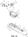
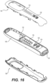
- FIG. 16 is a partially exploded view involving the front cover, the frame, and the rear cover in FIG. 14 .
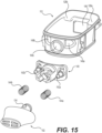
- various mechanical elements, electronic elements, and/or circuitry associated with the operation of the non-nicotine e-vaping device 500 may be secured to the frame 106.
- the front cover 104 and the rear cover 108 may be configured to engage with the frame 106 via a snap-fit arrangement.
- the front cover 104 and the rear cover 108 include clips configured to interlock with corresponding mating members of the frame 106.
- the clips may be in a form of tabs with orifices configured to receive the corresponding mating members (e.g., protrusions with beveled edges) of the frame 106.
- the front cover 104 has two rows with four clips each (for a total of eight clips for the front cover 104).
- the rear cover 108 has two rows with four clips each (for a total of eight clips for the rear cover 108).
- the corresponding mating members of the frame 106 may on the inner sidewalls of the frame 106. As a result, the engaged clips and mating members may be hidden from view when the front cover 104 and the rear cover 108 are snapped together.
- the front cover 104 and/or the rear cover 108 may be configured to engage with the frame 106 via an interference fit.
- the front cover 104, the frame 106, and the rear cover 108 may be coupled via other suitable arrangements and techniques.
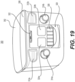
- the external face of the connector module 320 defines a pod inlet 322.
- the pod inlet 322 (through which air enters during vaping) is in fluidic communication with the pod outlet 304 (through which non-nicotine vapor exits during vaping).
- the pod inlet 322 is shown in FIG. 19 as being in a form of a slot. However, it should be understood that example embodiments are not limited thereto and that other forms are possible.
- the at least one electrical contact of the non-nicotine pod assembly 300 includes a plurality of data contacts 326.
- the plurality of data contacts 326 of the non-nicotine pod assembly 300 are configured to electrically connect with the data contacts of the device electrical connector 132 (e.g., row of five projections in FIG. 12 ). While two power contacts and five data contacts are shown in connection with the non-nicotine pod assembly 300, it should be understood that other variations are possible depending on the design of the device body 100.
- the non-nicotine pod assembly 300 includes a front face, a rear face opposite the front face, a first side face between the front face and the rear face, a second side face opposite the first side face, an upstream end face, and a downstream end face opposite the upstream end face.
- the corners of the side and end faces e.g., corner of the first side face and the upstream end face, corner of upstream end face and the second side face, corner of the second side face and the downstream end face, corner of the downstream end face and the first side face
- the corners may be rounded. However, in some instances, the corners may be angular.
- the peripheral edge of the front face may be in a form of a ledge.
- the external face of the connector module 320 may be regarded as being part of the upstream end face of the non-nicotine pod assembly 300.
- the front face of the non-nicotine pod assembly 300 may be wider and longer than the rear face.
- the first side face and the second side face may be angled inwards towards each other.
- the upstream end face and the downstream end face may also be angled inwards towards each other. Because of the angled faces, the insertion of the non-nicotine pod assembly 300 will be unidirectional (e.g., from the front side (side associated with the front cover 104) of the device body 100). As a result, the possibility that the non-nicotine pod assembly 300 will be improperly inserted into the device body 100 can be reduced or prevented.
- the pod body of the non-nicotine pod assembly 300 includes a first housing section 302 and a second housing section 308.
- the first housing section 302 has a downstream end defining the pod outlet 304.
- the rim of the pod outlet 304 may optionally be a sunken or indented region. In such an instance, this region may resemble a cove, wherein the side of the rim adjacent to the rear face of the non-nicotine pod assembly 300 may be open, while the side of the rim adjacent to the front face may be surrounded by a raised portion of the downstream end of the first housing section 302.
- the raised portion may function as a stopper for the distal end of the mouthpiece 102.
- this configuration for the pod outlet 304 may facilitate the receiving and aligning of the distal end of the mouthpiece 102 (e.g., FIG. 11 ) via the open side of the rim and its subsequent seating against the raised portion of the downstream end of the first housing section 302.
- the distal end of the mouthpiece 102 may also include (or be formed of) a resilient material to help create a seal around the pod outlet 304 when the non-nicotine pod assembly 300 is properly inserted within the through hole 150 of the device body 100.
- the downstream end of the first housing section 302 additionally defines at least one downstream recess.
- the at least one downstream recess is in a form of a first downstream recess 306a and a second downstream recess 306b.
- the pod outlet 304 may be between the first downstream recess 306a and the second downstream recess 306b.
- the first downstream recess 306a and the second downstream recess 306b are configured to engage with the first downstream protrusion 130a and the second downstream protrusion 130b, respectively, of the device body 100.
- the first downstream protrusion 130a and the second downstream protrusion 130b of the device body 100 may be disposed on adjacent corners of the downstream sidewall of the through hole 150.
- the first downstream recess 306a and the second downstream recess 306b may each be in a form of a V-shaped notch.
- each of the first downstream protrusion 130a and the second downstream protrusion 130b of the device body 100 may be in a form of a wedge-shaped structure configured to engage with a corresponding V-shaped notch of the first downstream recess 306a and the second downstream recess 306b.
- the first downstream recess 306a may abut the corner of the downstream end face and the first side face
- the second downstream recess 306b may abut the corner of the downstream end face and the second side face.
- each of the first downstream recess 306a and the second downstream recess 306b adjacent to the first side face and the second side face, respectively, may be open.
- each of the first downstream recess 306a and the second downstream recess 306b may be a 3-sided recess.
- the second housing section 308 has an upstream end defining the cavity 310 ( FIG. 20 ).
- the cavity 310 is configured to receive the connector module 320 ( FIG. 21 ).
- the upstream end of the second housing section 308 defines at least one upstream recess.
- the at least one upstream recess is in a form of a first upstream recess 312a and a second upstream recess 312b.
- the pod inlet 322 may be between the first upstream recess 312a and the second upstream recess 312b.
- the first upstream recess 312a and the second upstream recess 312b are configured to engage with the first upstream protrusion 128a and the second upstream protrusion 128b, respectively, of the device body 100.
- the first upstream protrusion 128a and the second upstream protrusion 128b of the device body 100 may be disposed on adjacent corners of the upstream sidewall of the through hole 150.
- a depth of each of the first upstream recess 312a and the second upstream recess 312b may be greater than a depth of each of the first downstream recess 306a and the second downstream recess 306b.
- a terminus of each of the first upstream recess 312a and the second upstream recess 312b may also be more rounded than a terminus of each of the first downstream recess 306a and the second downstream recess 306b.
- the first upstream recess 312a and the second upstream recess 312b may each be in a form of a U-shaped indentation.
- each of the first upstream protrusion 128a and the second upstream protrusion 128b of the device body 100 may be in a form of a rounded knob configured to engage with a corresponding U-shaped indentation of the first upstream recess 312a and the second upstream recess 312b.
- the first upstream recess 312a may abut the corner of the upstream end face and the first side face, while the second upstream recess 312b may abut the corner of the upstream end face and the second side face.
- the edges of the first upstream recess 312a and the second upstream recess 312b adjacent to the first side face and the second side face, respectively, may be open.
- the first housing section 302 may define a non-nicotine reservoir within configured to hold the non-nicotine pre-vapor formulation.
- the non-nicotine reservoir may be configured to hermetically seal the non-nicotine pre-vapor formulation until an activation of the non-nicotine pod assembly 300 to release the non-nicotine pre-vapor formulation from the non-nicotine reservoir.
- the non-nicotine pod assembly 300 may be activated manually by an adult vaper prior to the insertion of the non-nicotine pod assembly 300 into the device body 100. Alternatively, the non-nicotine pod assembly 300 may be activated as part of the insertion of the non-nicotine pod assembly 300 into the device body 100.
- the second housing section 308 of the pod body includes a perforator configured to release the non-nicotine pre-vapor formulation from the non-nicotine reservoir during the activation of the non-nicotine pod assembly 300.
- the perforator may be in a form of a first activation pin 314a and a second activation pin 314b, which will be discussed in more detail herein.
- an adult vaper may press the first activation pin 314a and the second activation pin 314b inward (e.g., simultaneously or sequentially) prior to inserting the non-nicotine pod assembly 300 into the through hole 150 of the device body 100.
- the first activation pin 314a and the second activation pin 314b may be manually pressed until the ends thereof are substantially even with the upstream end face of the non-nicotine pod assembly 300.
- the inward movement of the first activation pin 314a and the second activation pin 314b causes a seal of the non-nicotine reservoir to be punctured or otherwise compromised so as to release the non-nicotine pre-vapor formulation therefrom.
- the non-nicotine pod assembly 300 is initially positioned such that the first upstream recess 312a and the second upstream recess 312b are engaged with the first upstream protrusion 128a and the second upstream protrusion 128b, respectively (e.g., upstream engagement).
- each of the first upstream protrusion 128a and the second upstream protrusion 128b of the device body 100 may be in a form of a rounded knob configured to engage with a corresponding U-shaped indentation of the first upstream recess 312a and the second upstream recess 312b, the non-nicotine pod assembly 300 may be subsequently pivoted with relative ease about the first upstream protrusion 128a and the second upstream protrusion 128b and into the through hole 150 of the device body 100.
- the axis of rotation may be regarded as extending through the first upstream protrusion 128a and the second upstream protrusion 128b and oriented orthogonally to a longitudinal axis of the device body 100.
- the first activation pin 314a and the second activation pin 314b will come into contact with the upstream sidewall of the through hole 150 and transition from a protracted state to a retracted state as the first activation pin 314a and the second activation pin 314b are pushed (e.g., simultaneously) into the second housing section 308 as the non-nicotine pod assembly 300 progresses into the through hole 150.
- the first downstream protrusion 130a and the second downstream protrusion 130b will retract and then resiliently protract (e.g., spring back) when the positioning of the non-nicotine pod assembly 300 allows the first downstream protrusion 130a and the second downstream protrusion 130b of the device body 100 to engage with the first downstream recess 306a and the second downstream recess 306b, respectively, of the non-nicotine pod assembly 300 (e.g., downstream engagement).
- resiliently protract e.g., spring back
- the mouthpiece 102 is secured to the retention structure 140 (of which the first downstream protrusion 130a and the second downstream protrusion 130b are a part).
- the retraction of the first downstream protrusion 130a and the second downstream protrusion 130b from the through hole 150 will cause a simultaneous shift of the mouthpiece 102 by a corresponding distance in the same direction (e.g., downstream direction).
- the mouthpiece 102 will spring back simultaneously with the first downstream protrusion 130a and the second downstream protrusion 130b when the non-nicotine pod assembly 300 has been sufficiently inserted to facilitate downstream engagement.
- the distal end of the mouthpiece 102 is configured to also be biased against the non-nicotine pod assembly 300 (and aligned with the pod outlet 304 so as to form a relatively vapor-tight seal) when the non-nicotine pod assembly 300 is properly seated within the through hole 150 of the device body 100.
- the downstream engagement may produce an audible click and/or a haptic feedback to indicate that the non-nicotine pod assembly 300 is properly seated within the through hole 150 of the device body 100.
- the non-nicotine pod assembly 300 When properly seated, the non-nicotine pod assembly 300 will be connected to the device body 100 mechanically, electrically, and fluidically.
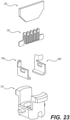
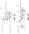
- FIG. 23 is an exploded view involving the wick, heater, electrical leads, and contact core in FIG. 22 .
- the wick 338 may be a fibrous pad or other structure with pores/interstices designed for capillary action.
- the wick 338 may have a shape of an irregular hexagon, although example embodiments are not limited thereto.
- the wick 338 may be fabricated into the hexagonal shape or cut from a larger sheet of material into this shape. Because the lower section of the wick 338 is tapered towards the winding section of the heater 336, the likelihood of the non-nicotine pre-vapor formulation being in a part of the wick 338 that continuously evades vaporization (due to its distance from the heater 336) can be reduced or avoided.
- FIG. 24 is an exploded view involving the first housing section of the non-nicotine pod assembly of FIG. 17 .
- the first housing section 302 includes a vapor channel 316.
- the vapor channel 316 is configured to receive non-nicotine vapor generated by the heater 336 and is in fluidic communication with the pod outlet 304.
- the vapor channel 316 may gradually increase in size (e.g., diameter) as it extends towards the pod outlet 304.
- the vapor channel 316 may be integrally formed with the first housing section 302.
- the insert 342 includes a holder portion that projects from the upstream side (as shown in FIG. 24 ) and a connector portion that projects from the downstream side (hidden from view in FIG. 24 ).
- the holder portion of the insert 342 is configured to hold the absorbent material 346, while the connector portion of the insert 342 is configured to engage with the vapor channel 316 of the first housing section 302.
- the connector portion of the insert 342 may be configured to be seated within the vapor channel 316 and, thus, engage the interior of the vapor channel 316.
- the connector portion of the insert 342 may be configured to receive the vapor channel 316 and, thus, engage with the exterior of the vapor channel 316.
- the insert 342 also defines non-nicotine reservoir outlets through which the non-nicotine pre-vapor formulation flows when the seal 344 is punctured (as shown in FIG. 24 ) during the activation of the non-nicotine pod assembly 300.
- the holder portion and the connector portion of the insert 342 may be between the non-nicotine reservoir outlets (e.g., first and second non-nicotine reservoir outlets), although example embodiments are not limited thereto.
- the insert 342 defines a vapor conduit extending through the holder portion and the connector portion.
- the vapor conduit of the insert 342 will be aligned with and in fluidic communication with the vapor channel 316 so as to form a continuous path through the non-nicotine reservoir to the pod outlet 304 for the non-nicotine vapor generated by the heater 336 during vaping.
- the seal 344 may be a coated foil (e.g., aluminum-backed Tritan).
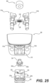
- FIG. 25 is a partially exploded view involving the second housing section of the non-nicotine pod assembly of FIG. 17 .
- the second housing section 308 is structured to contain various elements configured to release, receive, and heat the non-nicotine pre-vapor formulation.
- the first activation pin 314a and the second activation pin 314b are configured to puncture the non-nicotine reservoir in the first housing section 302 to release the non-nicotine pre-vapor formulation.
- Each of the first activation pin 314a and the second activation pin 314b has a distal end that extends through corresponding openings in the second housing section 308.
- first activation pin 314a and the second activation pin 314b are visible after assembly (e.g., FIG. 17 ), while the remainder of the first activation pin 314a and the second activation pin 314b are hidden from view within the non-nicotine pod assembly 300.
- each of the first activation pin 314a and the second activation pin 314b has a proximal end that is positioned so as to be adjacent to and upstream from the seal 344 prior to activation of the non-nicotine pod assembly 300.
- first activation pin 314a and the second activation pin 314b When the first activation pin 314a and the second activation pin 314b are pushed into the second housing section 308 to activate the non-nicotine pod assembly 300, the proximal end of each of the first activation pin 314a and the second activation pin 314b will advance through the insert 342 and, as a result, puncture the seal 344, which will release the non-nicotine pre-vapor formulation from the non-nicotine reservoir.
- the movement of the first activation pin 314a may be independent of the movement of the second activation pin 314b (and vice versa).
- the first activation pin 314a and the second activation pin 314b will be discussed in more detail herein.
- the absorbent material 346 is configured to engage with the holder portion of the insert 342 (which, as shown in FIG. 24 , projects from the upstream side of the insert 342).
- the absorbent material 346 may have an annular form, although example embodiments are not limited thereto.
- the absorbent material 346 may resemble a hollow cylinder.
- the outer diameter of the absorbent material 346 may be substantially equal to (or slightly larger than) the length of the wick 338.
- the inner diameter of the absorbent material 346 may be smaller than the average outer diameter of the holder portion of the insert 342 so as to result in an interference fit.
- the tip of the holder portion of the insert 342 may be tapered.
- the downstream side of the second housing section 308 may define a concavity configured receive and support the absorbent material 346.
- An example of such a concavity may be a circular chamber that is in fluidic communication with and downstream from the cavity 310.
- the absorbent material 346 is configured to receive and hold a quantity of the non-nicotine pre-vapor formulation released from the non-nicotine reservoir when the non-nicotine pod assembly 300 is activated.
- the wick 338 is positioned within the non-nicotine pod assembly 300 so as to be in fluidic communication with the absorbent material 346 such that the non-nicotine pre-vapor formulation can be drawn from the absorbent material 346 to the heater 336 via capillary action.
- the wick 338 may physically contact an upstream side of the absorbent material 346 (e.g., bottom of the absorbent material 346 based on the view shown in FIG. 25 ).
- the wick 338 may be aligned with a diameter of the absorbent material 346, although example embodiments are not limited thereto.
- the heater 336 may have a folded configuration so as to grip and establish thermal contact with the opposing surfaces of the wick 338.
- the heater 336 is configured to heat the wick 338 during vaping to generate a vapor.
- the first end of the heater 336 may be electrically connected to the first power contact 324a via the first electrical lead 340a, while the second end of the heater 336 may be electrically connected to the second power contact 324b via the second electrical lead 340b.
- an electric current may be supplied from a power source (e.g., battery) within the device body 100 and conveyed to the heater 336 via the first power contact 324a and the first electrical lead 340a (or via the second power contact 324b and the second electrical lead 340b).
- the first electrical lead 340a and the second electrical lead 340b (which are shown separately in FIG. 23 ) may be engaged with the contact core 334 (as shown in FIG. 25 ).
- the relevant details of other aspects of the connector module 320 which is configured to be seated within the cavity 310 of the second housing section 308, that have been discussed supra (e.g., in connection with FIGS. 21-22 ) and will not be repeated in this section in the interest of brevity.
- the non-nicotine vapor generated by the heater 336 is drawn through the vapor conduit of the insert 342, through the vapor channel 316 of the first housing section 302, out the pod outlet 304 of the non-nicotine pod assembly 300, and through the vapor passage 136 of the mouthpiece 102 to the vapor outlet(s).
- FIG. 26 is an exploded view of the activation pin in FIG. 25 .
- the activation pin may be in the form of a first activation pin 314a and a second activation pin 314b. While two activation pins are shown and discussed in connection with the non-limiting embodiments herein, it should be understood that, alternatively, the non-nicotine pod assembly 300 may include only one activation pin.
- the first activation pin 314a may include a first blade 348a, a first actuator 350a, and a first O-ring 352a.
- the second activation pin 314b may include a second blade 348b, a second actuator 350b, and a second O-ring 352b.
- first blade 348a and the second blade 348b are configured to be mounted or attached to upper portions (e.g., proximal portions) of the first actuator 350a and the second actuator 350b, respectively.
- the mounting or attachment may be achieved via a snap-fit connection, an interference fit (e.g., friction fit) connection, an adhesive, or other suitable coupling technique.
- the top of each of the first blade 348a and the second blade 348b may have one or more curved or concave edges that taper upward to a pointed tip.
- each of the first blade 348a and the second blade 348b may have two pointed tips with a concave edge therebetween and a curved edge adjacent to each pointed tip.
- the radii of curvature of the concave edge and the curved edges may be the same, while their arc lengths may differ.
- the first blade 348a and the second blade 348b may be formed of a sheet metal (e.g., stainless steel) that is cut or otherwise shaped to have the desired profile and bent to its final form. In another instance, the first blade 348a and the second blade 348b may be formed of plastic.
- the size and shape of the first blade 348a, the second blade 348b, and portions of the first actuator 350a and the second actuator 350b on which they are mounted may correspond to the size and shape of the non-nicotine reservoir outlets in the insert 342.
- the first actuator 350a and the second actuator 350b may include projecting edges (e.g., curved inner lips which face each other) configured to push the two punctured sections of the seal 344 into the non-nicotine reservoir as the first blade 348a and the second blade 348b advance into the non-nicotine reservoir.
- the two flaps may be between the curved sidewalls of the non-nicotine reservoir outlets of the insert 342 and the corresponding curvatures of the projecting edges of the first actuator 350a and the second actuator 350b.
- the first actuator 350a and the second actuator 350b may be configured to guide the non-nicotine pre-vapor formulation from the non-nicotine reservoir toward the absorbent material 346.
- each of the first actuator 350a and the second actuator 350b is configured to extend through a bottom section (e.g., upstream end) of the second housing section 308.
- This rod-like portion of each of the first actuator 350a and the second actuator 350b may also be referred to as the shaft.
- the first O-ring 352a and the second O-ring 352b may be seated in annular grooves in the respective shafts of the first actuator 350a and the second actuator 350b.
- the first O-ring 352a and the second O-ring 352b are configured to engage with the shafts of the first actuator 350a and the second actuator 350b as well as the inner surfaces of the corresponding openings in the second housing section 308 in order to provide a fluid-tight seal.
- the first O-ring 352a and the second O-ring 352b may move together with the respective shafts of the first actuator 350a and the second actuator 350b within the corresponding openings in the second housing section 308 while maintaining their respective seals, thereby helping to reduce or prevent leakage of the non-nicotine pre-vapor formulation through the openings in the second housing section 308 for the first activation pin 314a and the second activation pin 314b.
- the first O-ring 352a and the second O-ring 352b may be formed of silicone.
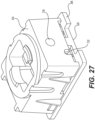
- FIG. 27 is a perspective view of the connector module of FIG. 22 without the wick, heater, electrical leads, and contact core.
- FIG. 28 is an exploded view of the connector module of FIG. 27 .
- the module housing 354 and the face plate 366 generally form the exterior framework of the connector module 320.
- the module housing 354 defines the first module inlet 330 and a grooved edge 356.
- the grooved edge 356 of the module housing 354 exposes the second module inlet 332 (which is defined by the bypass structure 358).
- the grooved edge 356 may also be regarded as defining a module inlet (e.g., in combination with the face plate 366).
- the face plate 366 has a grooved edge 328 which, together with the corresponding side surface of the cavity 310 of the second housing section 308, defines the pod inlet 322.
- the face plate 366 defines a first contact opening, a second contact opening, and a third contact opening.
- the first contact opening and the second contact opening may be square-shaped and configured to expose the first power contact 324a and the second power contact 324b, respectively, while the third contact opening may be rectangular-shaped and configured to expose the plurality of data contacts 326, although example embodiments are not limited thereto.
- the first power contact 324a, the second power contact 324b, a printed circuit board (PCB) 362, and the bypass structure 358 are disposed within the exterior framework formed by the module housing 354 and the face plate 366.
- the printed circuit board (PCB) 362 includes the plurality of data contacts 326 on its upstream side (which is hidden from view in FIG. 28 ) and a sensor 364 on its downstream side.
- the bypass structure 358 defines the second module inlet 332 and a bypass outlet 360.
- the first power contact 324a and the second power contact 324b are positioned so as to be visible through the first contact opening and the second contact opening, respectively, of the face plate 366.
- the printed circuit board (PCB) 362 is positioned such that the plurality of data contacts 326 on its upstream side are visible through the third contact opening of the face plate 366.
- the printed circuit board (PCB) 362 may also overlap the rear surfaces of the first power contact 324a and the second power contact 324b.
- the bypass structure 358 is positioned on the printed circuit board (PCB) 362 such that the sensor 364 is within an air flow path defined by the second module inlet 332 and the bypass outlet 360.
- bypass structure 358 and the printed circuit board (PCB) 362 may be regarded as being surrounded on at least four sides by the meandering structures of the first power contact 324a and the second power contact 324b.
- the bifurcated ends of the first power contact 324a and the second power contact 324b are configured to electrically connect to the first electrical lead 340a and the second electrical lead 340b.
- the first module inlet 330 may receive a primary flow (e.g., larger flow) of the incoming air, while the second module inlet 332 may receive a secondary flow (e.g., smaller flow) of the incoming air.
- the secondary flow of the incoming air may improve the sensitivity of the sensor 364.
- the secondary flow rejoins with the primary flow to form a combined flow that is drawn into and through the contact core 334 so as to encounter the heater 336 and the wick 338.
- the primary flow may be 60 - 95% (e.g., 80 - 90%) of the incoming air
- the secondary flow may be 5 - 40% (e.g., 10 - 20%) of the incoming air.
- the first module inlet 330 may be a resistance-to-draw (RTD) port, while the second module inlet 332 may be a bypass port.
- the resistance-to-draw for the non-nicotine e-vaping device 500 may be adjusted by changing the size of the first module inlet 330 (rather than changing the size of the pod inlet 322).
- the size of the first module inlet 330 may be selected such that the resistance-to-draw is between 25 - 100 mmH 2 O (e.g., between 30 - 50 mmH 2 O). For instance, a diameter of 1.0 mm for the first module inlet 330 may result in a resistance-to-draw of 88.3 mmH 2 O.
- a diameter of 1.1 mm for the first module inlet 330 may result in a resistance-to-draw of 73.6 mmH 2 O.
- a diameter of 1.2 mm for the first module inlet 330 may result in a resistance-to-draw of 58.7 mmH 2 O.
- a diameter of 1.3 mm for the first module inlet 330 may result in a resistance-to-draw of 43.8 mmH 2 O.
- the size of the first module inlet 330 may be adjusted without affecting the external aesthetics of the non-nicotine pod assembly 300, thereby allowing for a more standardized product design for pod assemblies with various resistance-to-draw (RTD) while also reducing the likelihood of an inadvertent blockage of the incoming air.
- RTD resistance-to-draw
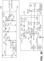
- FIG. 29 illustrates electrical systems of a device body and a non-nicotine pod assembly of a non-nicotine e-vaping device according to example embodiments.
- the electrical systems include a device body electrical system 2100 and a non-nicotine pod assembly electrical system 2200.
- the device body electrical system 2100 may be included in the device body 100
- the non-nicotine pod assembly electrical system 2200 may be included in the non-nicotine pod assembly 300 of the non-nicotine e-vaping device 500 discussed above with regard to FIGS. 1-28 .
- the non-nicotine pod assembly electrical system 2200 includes the heater 336 and a non-volatile memory (NVM) 2205.
- the NVM 2205 may be an electrically erasable programmable read-only memory (EEPROM) integrated circuit (IC).
- the non-nicotine pod assembly electrical system 2200 may further include a body electrical/data interface (not shown) for transferring power and/or data between the device body 100 and the non-nicotine pod assembly 300.
- a body electrical/data interface (not shown) for transferring power and/or data between the device body 100 and the non-nicotine pod assembly 300.
- the electrical contacts 324a, 324b and 326 shown in FIG. 17 may serve as the body electrical/data interface.
- the device body electrical system 2100 includes a controller 2105, a power supply 2110, device sensors 2125, a heating engine control circuit (also referred to as a heating engine shutdown circuit) 2127, vaper indicators 2135, on-product controls 2150 (e.g., buttons 118 and 120 shown in FIG. 1 ), a memory 2130, and a clock circuit 2128.
- the device body electrical system 2100 may further include a pod electrical/data interface (not shown) for transferring power and/or data between the device body 100 and the non-nicotine pod assembly 300.
- the device electrical connector 132 shown in FIG. 12 may serve as the pod electrical/data interface.
- the power supply 2110 may be an internal power source to supply power to the device body 100 and the non-nicotine pod assembly 300 of the non-nicotine e-vaping device 500.
- the supply of power from the power supply 2110 may be controlled by the controller 2105 through power control circuitry (not shown).
- the power control circuitry may include one or more switches or transistors to regulate power output from the power supply 2110.
- the power supply 2110 may be a Lithium-ion battery or a variant thereof (e.g., a Lithium-ion polymer battery).
- the controller 2105 may be configured to control overall operation of the non-nicotine e-vaping device 500.
- the controller 2105 may be implemented using hardware, a combination of hardware and software, or storage media storing software.
- hardware may be implemented using processing or control circuitry such as, but not limited to, one or more processors, one or more Central Processing Units (CPUs), one or more microcontrollers, one or more arithmetic logic units (ALUs), one or more digital signal processors (DSPs), one or more microcomputers, one or more field programmable gate arrays (FPGAs), one or more System-on-Chips (SoCs), one or more programmable logic units (PLUs), one or more microprocessors, one or more Application Specific Integrated Circuits (ASICs), or any other device or devices capable of responding to and executing instructions in a defined manner.
- CPUs Central Processing Units
- ALUs arithmetic logic units
- DSPs digital signal processors
- FPGAs field programm
- the controller 2105 is communicatively coupled to the device sensors 2125, the heating engine control circuit 2127, vaper indicators 2135, the memory 2130, the on-product controls 2150, the clock circuit 2128 and the power supply 2110.
- the heater current measurement circuit 21258 and the heater voltage measurement circuit 21252 are connected to the controller 2105 via pins of the multi-channel ADC.
- the multi-channel ADC at the controller 2105 may sample the output signals from the device sensors 2125 at a sampling rate appropriate for the given characteristic and/or parameter being measured by the respective device sensor.
- the device sensors 2125 may also include the sensor 364 shown in FIG. 28 .
- the sensor 364 may be a microelectromechanical system (MEMS) flow or pressure sensor or another type of sensor configured to measure air flow (e.g., a hot-wire anemometer).
- MEMS microelectromechanical system
- the heating engine control circuit 2127 is connected to the controller 2105 via a GPIO pin.
- the heating engine control circuit 2127 is configured to control (enable and/or disable) the heating engine of the non-nicotine e-vaping device 500 by controlling power to the heater 336.
- the heating engine control circuit 2127 may disable the heating engine based on control signaling (sometimes referred to herein as device power state signals) from the controller 2105.
- the controller 2105 When the non-nicotine pod assembly 300 is inserted into the device body 100, the controller 2105 is also communicatively coupled to at least the NVM 2205 via the I 2 C interface.
- the NVM 2205 may store non-nicotine pre-vapor formulation parameters and variable values for the non-nicotine pod assembly 300.
- non-nicotine pre-vapor formulation parameters may include a non-nicotine pre-vapor formulation empty threshold parameter (e.g., in microliters ( ⁇ L)), a non-nicotine pre-vapor formulation starting level (e.g., in ⁇ L), a non-nicotine pre-vapor formulation low threshold parameter (e.g., in ⁇ L), non-nicotine pre-vapor formulation vaporization parameters (e.g., vaporization rate), a sub-combination thereof, a combination thereof, or the like.
- the non-nicotine pre-vapor formulation variables may include a total amount of vaporized non-nicotine pre-vapor formulation (e.g., in ⁇ L) and/or a non-nicotine pre-vapor formulation empty flag.
- the non-nicotine pre-vapor formulation starting level indicates an initial level of the non-nicotine pre-vapor formulation in the non-nicotine reservoir of the non-nicotine pod assembly 300 when the non-nicotine pod assembly 300 is inserted into the device body 100.
- the initial level of the non-nicotine pre-vapor formulation in the non-nicotine reservoir may be determined at the time of filling or manufacturing the non-nicotine reservoir and/or non-nicotine pod assembly 300 prior to being inserted into the device body 100.
- the non-nicotine pre-vapor formulation vaporization parameters indicate, for example, a vaporization rate of the non-nicotine pre-vapor formulation (e.g., a vaporization rate conversion factor, such as pico-liters (pL) per milli-Joule (mJ) for the non-nicotine pre-vapor formulation in the non-nicotine pod assembly 300).
- a vaporization rate of the non-nicotine pre-vapor formulation e.g., a vaporization rate conversion factor, such as pico-liters (pL) per milli-Joule (mJ) for the non-nicotine pre-vapor formulation in the non-nicotine pod assembly 300.
- the non-nicotine pre-vapor formulation empty threshold parameter (also referred to herein as a non-nicotine pre-vapor formulation empty threshold or empty threshold) and the non-nicotine pre-vapor formulation low threshold parameter (also referred to herein as a non-nicotine pre-vapor formulation low threshold or low threshold) are threshold values that may be set based on empirical evidence.
- starting level of the non-nicotine pre-vapor formulation may be about 3500 ⁇ L
- a non-nicotine pre-vapor formulation low threshold parameter may be about 3000 ⁇ L
- a non-nicotine pre-vapor formulation empty threshold parameter may be about 3400 ⁇ L.
- the non-nicotine pre-vapor formulation empty threshold parameter may be less than the starting level of the non-nicotine pre-vapor formulation to provide a margin allowing for inaccuracies in the measurement of energy used.
- An example vaporization rate of the non-nicotine pre-vapor formulation may be about 280 pL/mJ, although the vaporization rate may be formulation dependent.
- the total amount of vaporized non-nicotine pre-vapor formulation indicates a total (aggregate) amount of non-nicotine pre-vapor formulation that has been drawn from the non-nicotine reservoir and/or vaporized during vaping or one or more puff events.
- the non-nicotine pre-vapor formulation empty flag may be a flag bit that is set when the total amount of vaporized non-nicotine pre-vapor formulation reaches or exceeds (is greater than or equal to) the non-nicotine pre-vapor formulation empty threshold parameter.
- the controller 2105 may control the vaper indicators 2135 to indicate statuses and/or operations of the non-nicotine e-vaping device 500 to an adult vaper.
- the vaper indicators 2135 may be at least partially implemented via a light guide (e.g., the light guide arrangement shown in FIG. 1 ), and may include a power indicator (e.g., LED) that may be activated when the controller 2105 senses a button pressed by the adult vaper.
- the vaper indicators 2135 may also include a vibration mechanism, speaker, or other feedback mechanisms, and may indicate a current state of an adult vaper-controlled vaping parameter (e.g., non-nicotine vapor volume).
- the controller 2105 may control power to the heater 336 to heat non-nicotine pre-vapor formulation drawn from the non-nicotine reservoir in accordance with a heating profile (e.g., volume, temperature, flavor, etc.).
- the heating profile may be determined based on empirical data and may be stored in the NVM 2205 of the non-nicotine pod assembly 300.
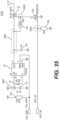
- FIG. 30 is a simple block diagram illustrating a non-nicotine pre-vapor formulation level detection and auto shutdown control system 2300 according to example embodiments.
- the non-nicotine pre-vapor formulation level detection and auto shutdown control system 2300 may be referred to herein as the auto shutdown control system 2300.
- the auto shutdown control system 2300 shown in FIG. 30 may be implemented at the controller 2105.
- the auto shutdown control system 2300 may be implemented as part of a device manager Finite State Machine (FSM) software implementation at the controller 2105.
- FSM Finite State Machine
- the auto shutdown control system 2300 includes a non-nicotine pre-vapor formulation level detection sub-system 2620. It should be understood, however, that the auto shutdown control system 2300 may include various other sub-system modules.
- the auto shutdown control system 2300 may determine the total amount of vaporized non-nicotine pre-vapor formulation and provide an indication of a level of the non-nicotine pre-vapor formulation (e.g., low, empty, depleted, or the like) remaining in the non-nicotine reservoir of the non-nicotine pod assembly 300 based on the determined total amount of vaporized non-nicotine pre-vapor formulation.
- a level of the non-nicotine pre-vapor formulation e.g., low, empty, depleted, or the like
- the auto shutdown control system 2300 may output an indication that the amount of non-nicotine pre-vapor formulation in the non-nicotine reservoir is relatively low (e.g., becoming depleted) when the total amount of vaporized non-nicotine pre-vapor formulation reaches or exceeds (is greater than or equal to) the non-nicotine pre-vapor formulation low threshold, but is less than the non-nicotine pre-vapor formulation empty threshold.
- the auto shutdown control system 2300 may output an indication that the non-nicotine pre-vapor formulation in the non-nicotine reservoir is depleted (e.g., empty) when the total amount of vaporized non-nicotine pre-vapor formulation reaches (is greater than or equal to) the non-nicotine pre-vapor formulation empty threshold.
- the non-nicotine pre-vapor formulation empty threshold may be greater than the non-nicotine pre-vapor formulation low threshold.
- the auto shutdown control system 2300 may indicate the level of non-nicotine pre-vapor formulation (e.g., low or depleted) via one or more of the vaper indicators 2135.
- the auto shutdown control system 2300 may also cause the controller 2105 to control one or more sub-systems of the non-nicotine e-vaping device 500 to perform one or more consequent actions.
- multiple consequent actions may be performed serially in response to the total amount of vaporized non-nicotine pre-vapor formulation reaching the non-nicotine pre-vapor formulation empty threshold.
- consequent actions may include:
- Depletion of the non-nicotine pre-vapor formulation in the non-nicotine reservoir is an example of a fault event (e.g., hard pod fault event) at the non-nicotine e-vaping device 500 that may require corrective action (e.g., replacement of a non-nicotine pod assembly) to re-enable the disabled functionality (e.g., vaping functions) at the non-nicotine e-vaping device 500.
- a fault event e.g., hard pod fault event
- corrective action e.g., replacement of a non-nicotine pod assembly
- the disabled functionality e.g., vaping functions
- the controller 2105 may control sub-systems of the non-nicotine e-vaping device 500 by outputting one or more control signals (or asserting or de-asserting a respective signal) as will be discussed in more detail later.
- the control signals output from the controller 2105 may be referred to as device power state signals, device power state instructions or device power control signals.
- the controller 2105 may output one or more control signals to the heating engine control circuit 2127 to shutdown vaping functions at the non-nicotine e-vaping device 500 in response to detecting depletion of the non-nicotine pre-vapor formulation in the non-nicotine reservoir at the non-nicotine e-vaping device 500.
- the auto shutdown control system 2300 determines the total amount of vaporized non-nicotine pre-vapor formulation by estimating an amount of non-nicotine pre-vapor formulation vaporized during each puff event and aggregating the estimated amounts.
- the auto shutdown control system 2300 may estimate the amount of vaporized non-nicotine pre-vapor formulation during a puff event based on an amount (e.g., aggregate amount) of power applied to the heater 336 during the puff event and a non-nicotine pre-vapor formulation vaporization parameter for the non-nicotine pod assembly 300 obtained from the NVM 2205.
- FIG. 31 is a flow chart illustrating a non-nicotine pre-vapor formulation level detection method according to example embodiments.
- example embodiments shown in FIG. 31 will be discussed with regard to the electrical systems shown in FIG. 29 . It should be understood, however, that example embodiments should not be limited to this example. Rather, example embodiments may be applicable to other non-nicotine e-vaping devices and electrical systems thereof. Moreover, the example embodiment shown in FIG. 32 will be described with regard to operations performed by the controller 2105. However, it should be understood that the example embodiment may be described similarly with regard to the auto shutdown control system 2300 and/or the non-nicotine pre-vapor formulation level detection sub-system 2620 performing one or more of the functions/operations shown in FIG. 31 .
- the controller 2105 obtains non-nicotine pre-vapor formulation parameters and variables from the NVM 2205 at step S2802.
- the controller 2105 determines whether the non-nicotine pre-vapor formulation empty flag is set.
- the non-nicotine pre-vapor formulation empty flag may be set or reset according to whether the total amount of vaporized non-nicotine pre-vapor formulation is greater than or equal to the non-nicotine pre-vapor formulation empty threshold parameter obtained from the NVM 2205.
- the set non-nicotine pre-vapor formulation empty flag may have a first bit value (e.g., '1' or '0'), whereas the reset non-nicotine pre-vapor formulation empty flag may have a second bit value (e.g., the other of '1' or '0').
- a set non-nicotine pre-vapor formulation empty flag indicates that the non-nicotine pre-vapor formulation in the non-nicotine pod assembly 300 is depleted (the non-nicotine reservoir in the non-nicotine pod assembly is empty), whereas a reset non-nicotine pre-vapor formulation empty flag indicates that the non-nicotine pre-vapor formulation in the non-nicotine pod assembly 300 is not depleted.
- the indication may be a blinking red LED, a software message containing an error code that is sent (e.g., via Bluetooth) to a connected "App" on a remote electronic device, which may subsequently trigger a notification in the App, a combination thereof, or the like.
- the controller 2105 controls the heating engine control circuit 2127 to perform a vaping-off operation.
- the vaping-off operation shuts down the vaping function by disabling all energy to the heater 336, thereby preventing vaping until corrective action is taken (e.g., by an adult vaper).
- the controller 2105 may control the heating engine control circuit 2127 to disable all energy to the heater 336 by outputting a vaping shutdown signal COIL_SHDN having a logic high level ( FIG. 35 ) or by de-asserting (or stopping output of) a vaping enable signal COIL_VGATE_PWM ( FIG. 36 ).
- the vaping enable signal COIL_VGATE_PWM may be a pulse width modulation (PWM) signal. Example corrective action will also be discussed in more detail later.
- step S2806 the controller 2105 determines whether vaping conditions exist at the non-nicotine e-vaping device 500.
- the controller 2105 may determine whether vaping conditions exist at the non-nicotine e-vaping device 500 based on output from the sensor 364. In one example, if the output from the sensor 364 indicates application of negative pressure above a threshold at the mouthpiece 102 of the non-nicotine e-vaping device 500, then the controller 2105 may determine that vaping conditions exist at the non-nicotine e-vaping device 500.
- step S2808 the controller 2105 begins integrating the power applied to the heater 336 to calculate the total energy applied to the heater 336 during the puff event (while vaping conditions are present).
- the controller 2105 since the power applied to the heater 336 may be adjusted dynamically during a puff event (intra-puff), the controller 2105 integrates or sums the power supplied to the heater 336 across the puff event to calculate the total energy applied to the heater 336 during the puff event.
- the controller 2105 determines whether vaping conditions have ceased (vaping conditions are no longer detected and the puff event has ended) at the non-nicotine e-vaping device 500.
- the controller 2105 determines that vaping conditions have ceased (end of the puff event), then at step S2812 the controller 2105 estimates the amount of non-nicotine pre-vapor formulation vaporized during the puff event (also referred to herein as a vaping time period or vaping interval) based on the energy applied to the heater 336 during the puff event.
- the energy applied to the heater 336 during the puff event may be linearly approximated to the amount of vaporized non-nicotine pre-vapor formulation by applying the vaporization rate conversion factor obtained from the NVM 2205 at step S2802.
- the estimated amount of vaporized non-nicotine pre-vapor formulation EST_AMT_VAP may be calculated as the product of the vaporization rate conversion factor VAP_CONV_FACTOR (pico-liters per milli-Joule) and the energy applied to the heater 336 during the puff event as shown below in Equation (2).
- EST _ AMT _ VAP VAP _ CONV _ FACTOR ⁇ E Applied
- the controller 2105 then calculates an updated estimate of the total amount of vaporized non-nicotine pre-vapor formulation (also referred to herein as the vaporized non-nicotine pre-vapor formulation value) for the non-nicotine pod assembly 300 by adding the amount of vaporized non-nicotine pre-vapor formulation estimated at step S2812 to the total amount of vaporized non-nicotine pre-vapor formulation stored at the NVM 2205.
- an updated estimate of the total amount of vaporized non-nicotine pre-vapor formulation also referred to herein as the vaporized non-nicotine pre-vapor formulation value
- the controller 2105 compares the updated total amount of vaporized non-nicotine pre-vapor formulation with the non-nicotine pre-vapor formulation empty threshold parameter obtained from the NVM 2205 at step S2802.
- the controller 2105 controls the vaper indicators 2135 (via control signal(s)) to output an indication that the non-nicotine pre-vapor formulation in the non-nicotine pod assembly 300 is depleted (e.g., the non-nicotine reservoir in the non-nicotine pod assembly 300 is empty).
- the controller 2105 stores the updated total amount of vaporized non-nicotine pre-vapor formulation at the NVM 2205 and sets the empty flag at the NVM 2205 to indicate that the non-nicotine pre-vapor formulation in the non-nicotine pod assembly 300 is depleted.
- Setting the empty flag at the NVM 2205 also serves as a write lock to prevent any further updates to the total amount of formulation. This write lock also prevents clearing of the empty flag.
- step S2816 if the updated total amount of vaporized non-nicotine pre-vapor formulation is less than the non-nicotine pre-vapor formulation empty threshold parameter, then the controller 2105 compares the updated total amount of vaporized non-nicotine pre-vapor formulation with the non-nicotine pre-vapor formulation low threshold parameter at step S2822.
- the controller 2105 controls the vaper indicators 2135 (via control signal(s)) to output a low non-nicotine pre-vapor formulation indication.
- the low non-nicotine pre-vapor formulation indication may be in the form of a sound, visual display and/or haptic feedback to an adult vaper.
- the indication may be a blinking yellow LED, a software message containing a code that is sent (e.g., via Bluetooth) to a connected "App" on a remote electronic device, which may subsequently trigger a notification in the App, a combination thereof, or the like.
- step S2828 the controller 2105 then updates the total amount of vaporized non-nicotine pre-vapor formulation at the NVM 2205, and the process then returns to step S2804 and continues as discussed above.
- step S2822 if the updated total amount of vaporized non-nicotine pre-vapor formulation is less than the non-nicotine pre-vapor formulation low threshold parameter, then the process proceeds to step S2828 and continues as discussed herein.
- step S2810 if the controller 2105 determines that vaping conditions have not yet ceased (a puff event has not ended) after vaping conditions are detected, then the controller 2105 continues to control the power control circuitry to apply power to the heater 336 and integrate the applied power. Once the controller 2105 determines that vaping conditions have ceased, the process continues as discussed above.
- step S2806 if the controller 2105 determines that vaping conditions are not yet present after determining that the non-nicotine pre-vapor formulation empty flag is not set, then the controller 2105 continues to monitor output of the sensor 364 for the presence of vaping conditions. Once the controller 2105 detects vaping conditions, the process proceeds to step S2808 and continues as discussed above.
- example embodiments should not be limited to this example.
- depletion of (empty) non-nicotine pre-vapor formulation in the non-nicotine reservoir may be determined by comparison with respective minimum non-nicotine pre-vapor formulation threshold parameters.
- the controller 2105 may determine whether the non-nicotine pre-vapor formulation in the non-nicotine reservoir is depleted (empty) by computing the difference between a starting level of the non-nicotine pre-vapor formulation in the non-nicotine reservoir and the total vaporized non-nicotine pre-vapor formulation calculated at step S2814, and then comparing the computed difference with a minimum non-nicotine pre-vapor formulation empty threshold parameter at step S2816. In this example, if the computed difference is less than the minimum non-nicotine pre-vapor formulation empty threshold parameter, then the controller 2105 determines that the non-nicotine pre-vapor formulation in the non-nicotine reservoir is depleted.
- the controller 2105 may determine whether the non-nicotine pre-vapor formulation in the non-nicotine reservoir is low by computing the difference between a starting level of the non-nicotine pre-vapor formulation in the non-nicotine reservoir and the total vaporized non-nicotine pre-vapor formulation calculated at step S2814, and then comparing the computed difference with a minimum non-nicotine pre-vapor formulation low threshold parameter at step S2822. In this example, if the computed difference is less than the non-nicotine pre-vapor formulation low threshold parameter, but greater than the non-nicotine pre-vapor formulation empty threshold parameter, then the controller 2105 determines that the non-nicotine pre-vapor formulation in the non-nicotine reservoir is low.
- the starting level of the non-nicotine pre-vapor formulation may be about 3500 ⁇ L
- the non-nicotine pre-vapor formulation low threshold parameter may be about 500 ⁇ L
- the non-nicotine pre-vapor formulation empty threshold parameter may be about 100 ⁇ L.
- the non-nicotine pre-vapor formulation empty threshold parameter may be greater than zero to provide a margin allowing for inaccuracies in the measurement of energy used.
- a fault event is an event that results in one or more consequent actions (e.g., a vaping off operation and/or an auto off operation) at the non-nicotine e-vaping device 500.
- FIG. 32 is a flow chart illustrating an example method of operation of a non-nicotine e-vaping device after performing a vaping-off operation in response to detecting a fault event, such as depletion of non-nicotine pre-vapor formulation, according to example embodiments.
- a fault event such as depletion of non-nicotine pre-vapor formulation
- FIG. 32 will be discussed with regard to depletion of non-nicotine pre-vapor formulation.
- example embodiments should not be limited to this example.
- FIG. 32 will be discussed with regard to the electrical systems shown in FIG. 29 . It should be understood, however, that example embodiments should not be limited to this example. Rather, example embodiments may be applicable to other non-nicotine e-vaping devices and electrical systems thereof. Moreover, the example embodiment shown in FIG. 32 will be described with regard to operations performed by the controller 2105. However, it should be understood that the example embodiment may be described similarly with regard to the auto shutdown control system 2300 and/or the non-nicotine pre-vapor formulation level detection sub-system 2620 performing one or more of the functions/operations shown in FIG. 32 .
- the controller 2105 logs the occurrence of the fault event (depleted non-nicotine reservoir) in the memory 2130.
- the controller 2105 may store an identifier of the event (depletion of non-nicotine pre-vapor formulation) in association with the consequent action (e.g., the vaping-off operation) and the time at which the fault event and consequent action occurred.
- the controller 2105 determines whether the non-nicotine pod assembly 300 has been removed (corrective action) from the device body 100 within (prior to expiration of) a removal threshold time interval after (e.g., in response to) indicating that the non-nicotine pre-vapor formulation is depleted to the adult vaper.
- the controller 2105 may determine that the non-nicotine pod assembly 300 has been removed from the device body 100 digitally by checking that the set of five contacts 326 of the non-nicotine pod assembly have been removed.
- the controller 2105 may determine that the non-nicotine pod assembly has been removed from the device body 100 by sensing that the electrical contacts 324a, 324b and/or 326 of the non-nicotine pod assembly 300 have been disconnected from the device electrical connector 132 of the device body 100.
- the controller 2105 determines that the non-nicotine pod assembly 300 has been removed from the device body 100 within the removal threshold time interval after (e.g., in response to) indicating the depletion of the non-nicotine pre-vapor formulation to the adult vaper, then at step S3810 the controller 2105 controls the non-nicotine e-vaping device 500 to return to normal operation (a non-fault state). In this case, although energy to the heater 336 is still disabled because the non-nicotine pod assembly 300 has been removed, the non-nicotine e-vaping device 500 is otherwise ready to vape in response to application of negative pressure by an adult vaper once a new non-nicotine pod assembly has been inserted.
- the controller 2105 determines whether a new non-nicotine pod assembly has been inserted into the device body 100 within (prior to expiration of) an insert threshold time interval after removal of the non-nicotine pod assembly 300 and returning of the non-nicotine e-vaping device 500 to normal operation at step S3814.
- the removal threshold time interval and/or the insert threshold time interval may have a length between about 5 minutes and about 120 minutes.
- the removal threshold time interval and/or the insert threshold time interval may be set to a length within this range by an adult vaper.
- the controller 2105 may determine that a new non-nicotine pod assembly has been inserted into the device body 100 by sensing the resistance of the heater 336 between the electrical contacts 324a and 324b of the non-nicotine pod assembly 300 and the device electrical connector 132 of the device body 100.
- the controller 2105 may determine that a new non-nicotine pod assembly has been inserted into the device body 100 by sensing the presence of a pull-up resistor contained in the non-nicotine pod assembly 300 between the electrical contacts 326 of the non-nicotine pod assembly 300 and the device electrical connector 132 of the device body 100.
- the controller 2105 determines that a new non-nicotine pod assembly has been inserted into the device body 100 within the insert threshold time interval, then at step S3814 the controller 2105 controls the heating engine control circuit 2127 to re-enable the vaping module (e.g., enable application of power to the heater 336). As discussed in more detail later, the controller 2105 may control the heating engine control circuit 2127 to re-enable the vaping module by outputting the vaping shutdown signal COIL_SHDN having a logic low level ( FIG. 35 ) or asserting the vaping enable signal COIL_VGATE_PWM ( FIG. 36 ).
- step S3816 the controller 2105 outputs another one or more control signals to perform an auto-off operation, in which the non-nicotine e-vaping device 500 is powered off or enters a low-power mode.
- the controller 2105 may output a multitude or plurality of GPIO control lines (signals) to turn off all or substantially all peripherals of the non-nicotine e-vaping device 500 and cause the controller 2105 to enter a sleep state.
- step S3808 if the non-nicotine pod assembly 300 is not removed within the removal threshold time interval, then the process proceeds to step S3816 and continues as discussed above.
- FIG. 33 illustrates an example embodiment of the heater voltage measurement circuit 21252.
- the heater voltage measurement circuit 21252 includes a resistor 3702 and a resistor 3704 connected in a voltage divider configuration between a terminal configured to receive an input voltage signal COIL_OUT and ground.
- the input voltage signal COIL_OUT is the voltage input to (voltage at the input terminal of) the heater 336.
- a node N3716 between the resistor 3702 and the resistor 3704 is coupled to a positive input of an operational amplifier (Op-Amp) 3708.
- a capacitor 3706 is connected between the node N3716 and ground to form a low-pass filter circuit (an R/C filter) to stabilize the voltage input to the positive input of the Op-Amp 3708.
- the filter circuit may also reduce inaccuracy due to switching noise induced by PWM signals used to energize the heater 336, and have the same phase response/group delay for both current and voltage.
- the heater voltage measurement circuit 21252 further includes resistors 3710 and 3712 and a capacitor 3714.
- the resistor 3712 is connected between node N3718 and a terminal configured to receive an output voltage signal COIL_RTN.
- the output voltage signal COIL_RTN is the voltage output from (voltage at the output terminal of) the heater 336.
- Resistor 3710 and capacitor 3714 are connected in parallel between node N3718 and an output of the Op-Amp 3708. A negative input of the Op-Amp 3708 is also connected to node N3718.
- the resistors 3710 and 3712 and the capacitor 3714 are connected in a low-pass filter circuit configuration.
- the heater voltage measurement circuit 21252 utilizes the Op-Amp 3708 to measure the voltage differential between the input voltage signal COIL_OUT and the output voltage signal COIL_RTN, and output a scaled heater voltage measurement signal COIL_VOL that represents the voltage across the heater 336.
- the heater voltage measurement circuit 21252 outputs the scaled heater voltage measurement signal COIL_VOL to an ADC pin of the controller 2105 for digital sampling and measurement by the controller 2105.
- the gain of the Op-Amp 3708 may be set based on the surrounding passive electrical elements (e.g., resistors and capacitors) to improve the dynamic range of the voltage measurement.
- the dynamic range of the Op-Amp 3708 may be achieved by scaling the voltage so that the maximum voltage output matches the maximum input range of the ADC (e.g., about 1.8V).
- FIG. 34 illustrates an example embodiment of the heater current measurement circuit 21258 shown in FIG. 29 .
- the output voltage signal COIL_RTN is input to a four terminal (4T) measurement resistor 3802 connected to ground.
- the differential voltage across the four terminal measurement resistor 3802 is scaled by an Op-Amp 3806, which outputs a heater current measurement signal COIL_CUR indicative of the current through the heater 336.
- the heater current measurement signal COIL_CUR is output to an ADC pin of the controller 2105 for digital sampling and measurement of the current through the heater 336 at the controller 2105.
- the four terminal measurement resistor 3802 may be used to reduce error in the current measurement using a 'Kelvin Current Measurement' technique.
- separation of the current measurement path from the voltage measurement path may reduce noise on the voltage measurement path.
- the gain of the Op-Amp 3806 may be set to improve the dynamic range of the measurement.
- the Op-Amp 3806 outputs a differential voltage as the heater current measurement signal COIL_CUR to an ADC pin of the controller 2105 for sampling and measurement of the current through the heater 336 by the controller 2105.
- FIG. 35 is a circuit diagram illustrating a heating engine control circuit according to some example embodiments.
- the heating engine control circuit shown in FIG. 35 is an example of the heating engine control circuit 2127 shown in FIG. 29 .
- the heating engine control circuit 2127A includes a CMOS charge pump U2 configured to supply a power rail (e.g., about 7V power rail (7V_CP)) to one or more gate driver integrated circuits (ICs) to control the power FETs (heater power control circuitry, also referred to as a heating engine drive circuit or circuitry, not shown in FIG. 35 ) that energize the heater 336 in the non-nicotine pod assembly 300.
- a power rail e.g., about 7V power rail (7V_CP)
- ICs gate driver integrated circuits
- the charge pump U2 is controlled (selectively activated or deactivated) based on the vaping shutdown signal COIL_SHDN (device power state signal; also referred to as a vaping enable signal) from the controller 2105.
- the charge pump U2 is activated in response to output of the vaping shutdown signal COIL_SHDN having a logic low level, and deactivated in response to output of the coil shutdown signal COIL-SHDN having a logic high level.
- the controller 2105 may enable the heater activation signal GATE_ON to provide power to the heater power control circuitry and the heater 336.
- the controller 2105 may perform a vaping-off operation by outputting (enabling) the vaping shutdown signal COIL_SHDN having a logic high level to disable all power to the heater 336 until the vaping shutdown signal COIL_SHDN is disabled (transitioned to a logic low level) by the controller 2105.
- the controller 2105 may output the heater activation signal GATE_ON (another device power state signal) having a logic high level in response to detecting the presence of vaping conditions at the non-nicotine e-vaping device 500.
- the transistors e.g., field-effect transistors (FETs)
- FETs field-effect transistors
- the controller 2105 may output the heater activation signal GATE_ON having a logic low level to disable power to the heater 336, thereby performing a heater-off operation.
- the controller 2105 may perform a vaping-off operation by outputting the vaping shutdown signal COIL_SHDN having a logic high level to cut-off power to the gate driver, which in turn also cuts off power to the heater 336.
- the heating engine control circuit 2127A automatically pulls the vaping shutdown signal COIL_SHDN to a logic high level to automatically cut-off power to the heater 336.
- the capacitor C11 is connected between node N3801 and ground to provide a filter and non-nicotine reservoir for the input voltage to the charge pump U2.
- Resistor R43 is connected between ground and the gate of the transistor Q7A' at node N3804.
- the resistor R43 serves as a pull-down resistor to ensure that the transistor Q7A' is in a high impedance (OFF) state, thereby disabling power rail 7V_CP and cutting off power to the heater 336, if the heater activation signal GATE_ON is in an indeterminate state.
- Transistor Q5 is configured to selectively isolate the power rail 7V_CP from the VOUT pin of charge pump U2.
- the gate of the transistor Q5 is connected to node N3803, the drain of the transistor Q5 is connected to the output voltage terminal VOUT of the charge pump U2 at node N3802, and the source of the transistor Q5 serves as the output terminal for the power rail 7V_CP.
- This configuration allows the capacitor C10 to reach an operating voltage more quickly by isolating the load, and creates a fail-safe insofar as the vaping shutdown signal COIL_SHDN and heater activation signal GATE_ON must both be in the correct state to provide power to the heater 336.
Landscapes
- Health & Medical Sciences (AREA)
- Engineering & Computer Science (AREA)
- Bioinformatics & Cheminformatics (AREA)
- Pulmonology (AREA)
- Anesthesiology (AREA)
- Biomedical Technology (AREA)
- Heart & Thoracic Surgery (AREA)
- Hematology (AREA)
- Life Sciences & Earth Sciences (AREA)
- Animal Behavior & Ethology (AREA)
- General Health & Medical Sciences (AREA)
- Public Health (AREA)
- Veterinary Medicine (AREA)
- Human Computer Interaction (AREA)
- Pharmaceuticals Containing Other Organic And Inorganic Compounds (AREA)
Applications Claiming Priority (3)
| Application Number | Priority Date | Filing Date | Title |
|---|---|---|---|
| US16/929,348 US12193517B2 (en) | 2020-07-15 | 2020-07-15 | Non-nicotine electronic vaping devices having non-nicotine pre-vapor formulation level detection and auto shutdown |
| EP21740335.1A EP4175501B1 (fr) | 2020-07-15 | 2021-06-16 | Non-nicotine dispositif de génération d'aérosol avec détection de niveau et arret automatique |
| PCT/US2021/037597 WO2022015456A1 (fr) | 2020-07-15 | 2021-06-16 | Dispositifs de vapotage électroniques sans nicotine à détection de niveau de formulation de pré-vapeur sans nicotine et arrêt automatique |
Related Parent Applications (2)
| Application Number | Title | Priority Date | Filing Date |
|---|---|---|---|
| EP21740335.1A Division-Into EP4175501B1 (fr) | 2020-07-15 | 2021-06-16 | Non-nicotine dispositif de génération d'aérosol avec détection de niveau et arret automatique |
| EP21740335.1A Division EP4175501B1 (fr) | 2020-07-15 | 2021-06-16 | Non-nicotine dispositif de génération d'aérosol avec détection de niveau et arret automatique |
Publications (1)
| Publication Number | Publication Date |
|---|---|
| EP4581966A1 true EP4581966A1 (fr) | 2025-07-09 |
Family
ID=76859759
Family Applications (2)
| Application Number | Title | Priority Date | Filing Date |
|---|---|---|---|
| EP25155690.8A Pending EP4581966A1 (fr) | 2020-07-15 | 2021-06-16 | Non-nicotine dispositif de génération d'aérosol avec détection de niveau et arret automatique |
| EP21740335.1A Active EP4175501B1 (fr) | 2020-07-15 | 2021-06-16 | Non-nicotine dispositif de génération d'aérosol avec détection de niveau et arret automatique |
Family Applications After (1)
| Application Number | Title | Priority Date | Filing Date |
|---|---|---|---|
| EP21740335.1A Active EP4175501B1 (fr) | 2020-07-15 | 2021-06-16 | Non-nicotine dispositif de génération d'aérosol avec détection de niveau et arret automatique |
Country Status (7)
| Country | Link |
|---|---|
| US (2) | US12193517B2 (fr) |
| EP (2) | EP4581966A1 (fr) |
| JP (2) | JP7650954B2 (fr) |
| KR (1) | KR20230038560A (fr) |
| CN (1) | CN116390664A (fr) |
| CA (1) | CA3185557A1 (fr) |
| WO (1) | WO2022015456A1 (fr) |
Families Citing this family (2)
| Publication number | Priority date | Publication date | Assignee | Title |
|---|---|---|---|---|
| CN110226777B (zh) * | 2019-06-27 | 2025-02-11 | 深圳雾芯科技有限公司 | 电子雾化器、电子雾化器装置主体及电子雾化器装置 |
| US12550942B2 (en) | 2022-09-19 | 2026-02-17 | Altria Client Services Llc | Session control system |
Citations (4)
| Publication number | Priority date | Publication date | Assignee | Title |
|---|---|---|---|---|
| US20150208731A1 (en) * | 2014-01-27 | 2015-07-30 | Sis Resources Ltd. | Wire communication in an e-vaping device |
| US20170135406A1 (en) * | 2015-11-17 | 2017-05-18 | Altria Client Services Llc | Aerosol-generating system with self-activated electric heater |
| US20170231278A1 (en) * | 2016-02-12 | 2017-08-17 | Oleg Mironov | Aerosol-generating system with electrodes |
| WO2019173923A1 (fr) * | 2018-03-14 | 2019-09-19 | Canopy Growth Corporation | Dispositifs de vapotage, comprenant des cartouches, des comprimés, des capteurs et des commandes pour des dispositifs de vapotage, et leurs procédés de fabrication et d'utilisation |
Family Cites Families (39)
| Publication number | Priority date | Publication date | Assignee | Title |
|---|---|---|---|---|
| KR100658604B1 (ko) * | 2005-06-29 | 2006-12-19 | 롯데제과주식회사 | 니코틴 유사활성을 갖는 천연추출물 및 이를 이용한금연보조용 조성물 |
| CN201067079Y (zh) | 2006-05-16 | 2008-06-04 | 韩力 | 仿真气溶胶吸入器 |
| EP2106384B1 (fr) | 2006-11-20 | 2013-04-03 | Fuel Transfer Technologies Inc. | Mécanisme et système de pistolet distributeur à arrêt automatique activé par la récupération de vapeur |
| CN102396783B (zh) | 2010-09-15 | 2013-10-02 | 东莞市艾菲五金电子有限公司 | 一种电能吸烟器 |
| EP2468117A1 (fr) * | 2010-12-24 | 2012-06-27 | Philip Morris Products S.A. | Système de génération d'aérosol disposant de supports pour déterminer la déplétion d'un substrat liquide |
| EP2468116A1 (fr) | 2010-12-24 | 2012-06-27 | Philip Morris Products S.A. | Système de génération d'aérosol disposant de supports pour gérer la consommation d'un substrat liquide |
| EP2468118A1 (fr) * | 2010-12-24 | 2012-06-27 | Philip Morris Products S.A. | Système de génération d'aérosol afin de désactiver un consommable |
| US20130340775A1 (en) | 2012-04-25 | 2013-12-26 | Bernard Juster | Application development for a network with an electronic cigarette |
| US9158302B2 (en) | 2012-05-04 | 2015-10-13 | Siemens Energy, Inc. | System and method for detecting electric power plant equipment overheating with real-time plural parallel detection and analysis parameters |
| US9814262B2 (en) | 2012-07-11 | 2017-11-14 | Sis Resources, Ltd. | Hot-wire control for an electronic cigarette |
| US10117460B2 (en) | 2012-10-08 | 2018-11-06 | Rai Strategic Holdings, Inc. | Electronic smoking article and associated method |
| US9675114B2 (en) | 2012-11-08 | 2017-06-13 | Ludovicus Josephine Felicien Timmermans | Real time variable voltage programmable electronic cigarette and method |
| US20140230835A1 (en) | 2013-02-21 | 2014-08-21 | Sarmad Saliman | Disposable electronic cigarette with power shut off protection |
| CN104026743A (zh) | 2013-03-05 | 2014-09-10 | 向智勇 | 具有长时间加热保护功能的电子烟及其保护方法 |
| US9423152B2 (en) | 2013-03-15 | 2016-08-23 | R. J. Reynolds Tobacco Company | Heating control arrangement for an electronic smoking article and associated system and method |
| CN203166473U (zh) | 2013-03-20 | 2013-08-28 | 向智勇 | 电子烟或烟弹的过热保护装置 |
| US20140338685A1 (en) | 2013-05-20 | 2014-11-20 | Sis Resources, Ltd. | Burning prediction and communications for an electronic cigarette |
| TWI834585B (zh) * | 2013-07-30 | 2024-03-01 | 美商奧馳亞客戶服務有限責任公司 | 加味蒸汽產生裝置 |
| EP3068244A4 (fr) | 2013-11-15 | 2017-07-05 | VMR Products, LLC | Vaporisateur ayant une gaine de revêtement |
| EP2946679B1 (fr) | 2014-04-28 | 2019-09-25 | Shenzhen First Union Technology Co., Ltd. | Dispositif d'atomisation et cigarette électronique comportant celui-ci |
| CN104120308B (zh) | 2014-06-24 | 2017-01-04 | 深圳麦克韦尔股份有限公司 | 电子烟及其发热丝 |
| SI3166426T1 (sl) | 2014-07-11 | 2018-10-30 | Philip Morris Products S.A. | Sistem, ki proizvaja aerosol in obsega zaznavanje vložka |
| GB201413835D0 (en) | 2014-08-05 | 2014-09-17 | Nicoventures Holdings Ltd | Electronic vapour provision system |
| WO2016029225A1 (fr) | 2014-08-22 | 2016-02-25 | Fontem Holdings 2 B.V. | Procédé, système et dispositif de commande d'un élément chauffant |
| MX2017006381A (es) * | 2014-11-17 | 2017-08-21 | Mcneil Ab | Cartucho desechable para usarse en un sistema electronico de suministro de nicotina. |
| KR102627987B1 (ko) | 2014-12-05 | 2024-01-22 | 쥴 랩스, 인크. | 교정된 투여량 제어 |
| WO2016101248A1 (fr) * | 2014-12-26 | 2016-06-30 | 惠州市吉瑞科技有限公司 | Procédé de commande de cigarette électronique, et cigarette électronique |
| US10701981B2 (en) * | 2015-04-22 | 2020-07-07 | Altria Client Services Llc | Pod assembly and e-vapor apparatus including the same |
| US10687554B2 (en) * | 2015-04-22 | 2020-06-23 | Altria Client Services Llc | Connection device, cartridge and electronic vaping device |
| GB201517089D0 (en) * | 2015-09-28 | 2015-11-11 | Nicoventures Holdings Ltd | Vaping heat map system and method for electronic vapour provision systems |
| WO2017056282A1 (fr) | 2015-09-30 | 2017-04-06 | 日本たばこ産業株式会社 | Inhalateur d'arôme de type sans combustion et unité d'atomisation |
| IL265355B2 (en) | 2016-09-14 | 2026-02-01 | Altria Client Services Llc | Smoking device |
| JP6644157B2 (ja) | 2017-01-24 | 2020-02-12 | 日本たばこ産業株式会社 | 吸引装置並びにこれを動作させる方法及びプログラム |
| CN107156911A (zh) * | 2017-05-27 | 2017-09-15 | 深圳市合元科技有限公司 | 电子烟及使用方法 |
| US12232224B2 (en) | 2017-10-11 | 2025-02-18 | Altria Client Services Llc | Folded heater for electronic vaping device |
| CA3118314A1 (fr) | 2018-11-09 | 2020-05-14 | Juul Labs, Inc. | Vaporisation de protocoles de donnees associes |
| WO2020254252A1 (fr) * | 2019-06-21 | 2020-12-24 | Jt International Sa | Débitmètre massique pour cigarette électronique |
| JP7610362B2 (ja) * | 2020-07-08 | 2025-01-08 | 日本たばこ産業株式会社 | エアロゾル生成装置の制御ユニット |
| US12102132B2 (en) | 2020-07-15 | 2024-10-01 | Altria Client Services Llc | Nicotine electronic vaping devices having nicotine pre-vapor formulation level detection and auto shutdown |
-
2020
- 2020-07-15 US US16/929,348 patent/US12193517B2/en active Active
-
2021
- 2021-06-16 CA CA3185557A patent/CA3185557A1/fr active Pending
- 2021-06-16 KR KR1020237005282A patent/KR20230038560A/ko active Pending
- 2021-06-16 CN CN202180053473.6A patent/CN116390664A/zh active Pending
- 2021-06-16 JP JP2023502688A patent/JP7650954B2/ja active Active
- 2021-06-16 WO PCT/US2021/037597 patent/WO2022015456A1/fr not_active Ceased
- 2021-06-16 EP EP25155690.8A patent/EP4581966A1/fr active Pending
- 2021-06-16 EP EP21740335.1A patent/EP4175501B1/fr active Active
-
2024
- 2024-12-04 US US18/967,860 patent/US20250089806A1/en active Pending
-
2025
- 2025-03-12 JP JP2025039598A patent/JP2025090757A/ja active Pending
Patent Citations (4)
| Publication number | Priority date | Publication date | Assignee | Title |
|---|---|---|---|---|
| US20150208731A1 (en) * | 2014-01-27 | 2015-07-30 | Sis Resources Ltd. | Wire communication in an e-vaping device |
| US20170135406A1 (en) * | 2015-11-17 | 2017-05-18 | Altria Client Services Llc | Aerosol-generating system with self-activated electric heater |
| US20170231278A1 (en) * | 2016-02-12 | 2017-08-17 | Oleg Mironov | Aerosol-generating system with electrodes |
| WO2019173923A1 (fr) * | 2018-03-14 | 2019-09-19 | Canopy Growth Corporation | Dispositifs de vapotage, comprenant des cartouches, des comprimés, des capteurs et des commandes pour des dispositifs de vapotage, et leurs procédés de fabrication et d'utilisation |
Also Published As
| Publication number | Publication date |
|---|---|
| US20250089806A1 (en) | 2025-03-20 |
| EP4175501B1 (fr) | 2025-03-19 |
| EP4175501A1 (fr) | 2023-05-10 |
| US12193517B2 (en) | 2025-01-14 |
| JP2025090757A (ja) | 2025-06-17 |
| CA3185557A1 (fr) | 2022-01-20 |
| JP2023534250A (ja) | 2023-08-08 |
| US20220015439A1 (en) | 2022-01-20 |
| JP7650954B2 (ja) | 2025-03-25 |
| KR20230038560A (ko) | 2023-03-20 |
| CN116390664A (zh) | 2023-07-04 |
| WO2022015456A1 (fr) | 2022-01-20 |
Similar Documents
| Publication | Publication Date | Title |
|---|---|---|
| EP4176691B1 (fr) | Circuits de commande de moteur de chauffage et dispositifs de vapage électronique non nicotine y compris | |
| US12569010B2 (en) | Non-nicotine electronic vaping devices having dryness detection and auto shutdown | |
| EP4181715B1 (fr) | Dispositifs de vapotage électronique de nicotine à détection de siccité et à arrêt automatique | |
| US20240415195A1 (en) | Nicotine electronic vaping devices having nicotine pre-vapor formulation level detection and auto shutdown | |
| US20250089806A1 (en) | Non-nicotine electronic vaping devices having non-nicotine pre-vapor formulation level detection and auto shutdown | |
| EP4181705B1 (fr) | Circuits de commande de moteur de chauffage et dispositifs de vapage électronique nicotine y compris | |
| CA3185558A1 (fr) | Dispositifs de vapotage electroniques sans nicotine a arret automatique |
Legal Events
| Date | Code | Title | Description |
|---|---|---|---|
| PUAI | Public reference made under article 153(3) epc to a published international application that has entered the european phase |
Free format text: ORIGINAL CODE: 0009012 |
|
| STAA | Information on the status of an ep patent application or granted ep patent |
Free format text: STATUS: THE APPLICATION HAS BEEN PUBLISHED |
|
| AC | Divisional application: reference to earlier application |
Ref document number: 4175501 Country of ref document: EP Kind code of ref document: P |
|
| AK | Designated contracting states |
Kind code of ref document: A1 Designated state(s): AL AT BE BG CH CY CZ DE DK EE ES FI FR GB GR HR HU IE IS IT LI LT LU LV MC MK MT NL NO PL PT RO RS SE SI SK SM TR |
|
| STAA | Information on the status of an ep patent application or granted ep patent |
Free format text: STATUS: REQUEST FOR EXAMINATION WAS MADE |
|
| 17P | Request for examination filed |
Effective date: 20260109 |
|
| STAA | Information on the status of an ep patent application or granted ep patent |
Free format text: STATUS: EXAMINATION IS IN PROGRESS |
|
| 17Q | First examination report despatched |
Effective date: 20260302 |