EP4582000A1 - Lave-vaisselle et son procédé de commande - Google Patents
Lave-vaisselle et son procédé de commande Download PDFInfo
- Publication number
- EP4582000A1 EP4582000A1 EP23885966.4A EP23885966A EP4582000A1 EP 4582000 A1 EP4582000 A1 EP 4582000A1 EP 23885966 A EP23885966 A EP 23885966A EP 4582000 A1 EP4582000 A1 EP 4582000A1
- Authority
- EP
- European Patent Office
- Prior art keywords
- storage compartment
- solid detergent
- solid
- detergent
- seating member
- Prior art date
- Legal status (The legal status is an assumption and is not a legal conclusion. Google has not performed a legal analysis and makes no representation as to the accuracy of the status listed.)
- Pending
Links
Images








Classifications
-
- A—HUMAN NECESSITIES
- A47—FURNITURE; DOMESTIC ARTICLES OR APPLIANCES; COFFEE MILLS; SPICE MILLS; SUCTION CLEANERS IN GENERAL
- A47L—DOMESTIC WASHING OR CLEANING; SUCTION CLEANERS IN GENERAL
- A47L15/00—Washing or rinsing machines for crockery or tableware
- A47L15/42—Details
- A47L15/44—Devices for adding cleaning agents; Devices for dispensing cleaning agents, rinsing aids or deodorants
- A47L15/4463—Multi-dose dispensing arrangements
-
- A—HUMAN NECESSITIES
- A47—FURNITURE; DOMESTIC ARTICLES OR APPLIANCES; COFFEE MILLS; SPICE MILLS; SUCTION CLEANERS IN GENERAL
- A47L—DOMESTIC WASHING OR CLEANING; SUCTION CLEANERS IN GENERAL
- A47L15/00—Washing or rinsing machines for crockery or tableware
- A47L15/0018—Controlling processes, i.e. processes to control the operation of the machine characterised by the purpose or target of the control
- A47L15/0049—Detection or prevention of malfunction, including accident prevention
-
- A—HUMAN NECESSITIES
- A47—FURNITURE; DOMESTIC ARTICLES OR APPLIANCES; COFFEE MILLS; SPICE MILLS; SUCTION CLEANERS IN GENERAL
- A47L—DOMESTIC WASHING OR CLEANING; SUCTION CLEANERS IN GENERAL
- A47L15/00—Washing or rinsing machines for crockery or tableware
- A47L15/0018—Controlling processes, i.e. processes to control the operation of the machine characterised by the purpose or target of the control
- A47L15/0055—Metering or indication of used products, e.g. type or quantity of detergent, rinse aid or salt; for measuring or controlling the product concentration
-
- A—HUMAN NECESSITIES
- A47—FURNITURE; DOMESTIC ARTICLES OR APPLIANCES; COFFEE MILLS; SPICE MILLS; SUCTION CLEANERS IN GENERAL
- A47L—DOMESTIC WASHING OR CLEANING; SUCTION CLEANERS IN GENERAL
- A47L15/00—Washing or rinsing machines for crockery or tableware
- A47L15/42—Details
- A47L15/4293—Arrangements for programme selection, e.g. control panels; Indication of the selected programme, programme progress or other parameters of the programme, e.g. by using display panels
-
- A—HUMAN NECESSITIES
- A47—FURNITURE; DOMESTIC ARTICLES OR APPLIANCES; COFFEE MILLS; SPICE MILLS; SUCTION CLEANERS IN GENERAL
- A47L—DOMESTIC WASHING OR CLEANING; SUCTION CLEANERS IN GENERAL
- A47L15/00—Washing or rinsing machines for crockery or tableware
- A47L15/42—Details
- A47L15/44—Devices for adding cleaning agents; Devices for dispensing cleaning agents, rinsing aids or deodorants
-
- A—HUMAN NECESSITIES
- A47—FURNITURE; DOMESTIC ARTICLES OR APPLIANCES; COFFEE MILLS; SPICE MILLS; SUCTION CLEANERS IN GENERAL
- A47L—DOMESTIC WASHING OR CLEANING; SUCTION CLEANERS IN GENERAL
- A47L2301/00—Manual input in controlling methods of washing or rinsing machines for crockery or tableware, i.e. information entered by a user
- A47L2301/04—Operation mode, e.g. delicate washing, economy washing, reduced time, sterilizing, water softener regenerating, odor eliminating or service
-
- A—HUMAN NECESSITIES
- A47—FURNITURE; DOMESTIC ARTICLES OR APPLIANCES; COFFEE MILLS; SPICE MILLS; SUCTION CLEANERS IN GENERAL
- A47L—DOMESTIC WASHING OR CLEANING; SUCTION CLEANERS IN GENERAL
- A47L2401/00—Automatic detection in controlling methods of washing or rinsing machines for crockery or tableware, e.g. information provided by sensors entered into controlling devices
- A47L2401/02—Consumable products information, e.g. information on detergent, rinsing aid or salt; Dispensing device information, e.g. information on the type, e.g. detachable, or status of the device
-
- A—HUMAN NECESSITIES
- A47—FURNITURE; DOMESTIC ARTICLES OR APPLIANCES; COFFEE MILLS; SPICE MILLS; SUCTION CLEANERS IN GENERAL
- A47L—DOMESTIC WASHING OR CLEANING; SUCTION CLEANERS IN GENERAL
- A47L2401/00—Automatic detection in controlling methods of washing or rinsing machines for crockery or tableware, e.g. information provided by sensors entered into controlling devices
- A47L2401/30—Variation of electrical, magnetical or optical quantities
-
- A—HUMAN NECESSITIES
- A47—FURNITURE; DOMESTIC ARTICLES OR APPLIANCES; COFFEE MILLS; SPICE MILLS; SUCTION CLEANERS IN GENERAL
- A47L—DOMESTIC WASHING OR CLEANING; SUCTION CLEANERS IN GENERAL
- A47L2501/00—Output in controlling method of washing or rinsing machines for crockery or tableware, i.e. quantities or components controlled, or actions performed by the controlling device executing the controlling method
- A47L2501/07—Consumable products, e.g. detergent, rinse aids or salt
-
- A—HUMAN NECESSITIES
- A47—FURNITURE; DOMESTIC ARTICLES OR APPLIANCES; COFFEE MILLS; SPICE MILLS; SUCTION CLEANERS IN GENERAL
- A47L—DOMESTIC WASHING OR CLEANING; SUCTION CLEANERS IN GENERAL
- A47L2501/00—Output in controlling method of washing or rinsing machines for crockery or tableware, i.e. quantities or components controlled, or actions performed by the controlling device executing the controlling method
- A47L2501/26—Indication or alarm to the controlling device or to the user
Definitions
- the disclosure relates to a dishwasher and a control method thereof and more particularly, to a dishwasher including a device configured to input detergent, and a control method thereof.
- a dishwasher is a device that automatically removes food residues and the like on dishes using detergent and wash water.
- the dishwasher includes a main body, a washing chamber formed by a tub disposed inside the main body, a storage container disposed inside the washing chamber to store dishes, and a spray unit configured to spray wash water to the storage container.
- At least a portion of the drain hose may be arranged to have a curved shape at a position higher than the lower surface of the washing chamber.
- Embodiments of the disclosure may provide a dishwasher capable of storing a plurality of solid detergents and automatically inputting the solid detergent at a necessary time during washing, and a control method thereof.
- Embodiments of the disclosure may provide a dishwasher capable of increasing convenience of use by automatically detecting the presence or absence of stored solid detergent and by automatically detecting a solid detergent being stuck, and by providing feedback thereto, and a control method thereof.
- Embodiments of the disclosure may provide a dishwasher capable of inputting an appropriate amount of detergent by preventing over-input of detergent by storing and inputting different sizes of solid detergents by varying a size of a storage compartment, and a control method thereof.
- a dishwasher includes a tub; a door to open and close the tub; an input device to receive a selection of a washing course; and an automatic detergent dispenser including a storage compartment in which a plurality of solid detergents are stackable so as to be loaded in a vertical direction when the tub is closed by the door, an ejector to discharge a solid detergent, among the plurality of solid detergents loaded in the storage compartment, outside of the storage compartment, a seating member on which a solid detergent discharged from the storage compartment is seatable, a detector to detect whether a solid detergent is seated on the seating member, and a processor configured to, in response to a selection of a washing course being received through the input device, control the ejector to operate so that, when a plurality of solid detergents are loaded in the storage compartment, one solid detergent among the plurality of solid detergents is discharged outside of the storage compartment to be seated on the seating member, and determine whether a solid detergent is seated on the seating member based on a detection result of the
- the ejector may include a cam member configured to rotate in a forward direction to discharge the one solid detergent outside of the storage compartment, and the processor may be configured to rotate the cam member one time in the forward direction to discharge the one solid detergent outside of the storage compartment.
- the detector may include a seating member sensor to detect an object seated on the seating member, and the processor may be configured to determine whether a solid detergent is seated on the seating member based on an output of the seating member sensor.
- the automatic detergent dispenser may include a seating member door to open to input a solid detergent seated on the seating member into the tub, and the processor may be configured to open the seating member door to input the solid detergent seated on the seating member into the tub at a stage of supplying water for a main washing operation.
- the detector may include a storage compartment sensor to detect a solid detergent inside of the storage compartment, and the processor may be configured to determine whether a solid detergent is present in the storage compartment based on an output of the storage compartment sensor.
- the processor may be configured to determine whether an error in discharging the one solid detergent occurred based on the detection result of the detector, and rotate the cam member in a reverse direction in response to determining that the error occurred.
- the processor may be configured to determine whether an error in discharging the one solid detergent occurred based on power consumption or rotational speed of a motor inside the ejector.
- the storage compartment may include a first storage compartment, and a second storage compartment spaced apart from the first storage compartment in a left and right direction that is perpendicular to the vertical direction
- the ejector may include a first ejector to discharge a solid detergent, among a plurality of solid detergents loaded in the first storage compartment, to the seating member, and a second ejector to discharge a solid detergent, among a plurality of solid detergents loaded in the second storage compartment, to the seating member.
- the first ejector may include a first cam member configured to rotate in a forward direction to discharge the one solid detergent outside of the first storage compartment
- the second ejector may include a second cam member configured to rotate in the forward direction to move the one solid detergent outside of the second storage compartment
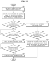
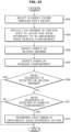
- control method may further include determining whether a solid detergent is seated on the seating member after rotating the cam member the second time; in response to determining that a solid detergent is not seated on the seating member after rotating the cam member the second time, determining that a solid detergent is not present in the storage compartment; and generating a control signal to provide a notification that a solid detergent is not present in the storage compartment.
- control may further include determining whether an error in discharging the one solid detergent occurred based on the detection result of the detector.
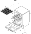
- FIG. 1 is a perspective view of a state in which a door of a dishwasher according to an embodiment is opened
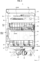
- FIG. 2 is a schematic side cross-sectional view of the dishwasher according to an embodiment
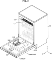
- FIG. 3 is a perspective view illustrating a state in which a detergent is loaded into an automatic detergent dispenser of the dishwasher according to an embodiment.
- a dishwasher 1 may include a tub 12 arranged inside a main body 10.
- the tub 12 may be formed in a substantially box shape. One side of the tub 12 may be opened.
- the tub 12 may include an opening 12a.
- a front surface of the tub 12 may be opened toward the first direction X.
- the dishwasher 1 may further include a door 20 configured to open and close the opening 12a of the tub 12.
- the door 20 may be installed in the main body 10 to open and close the opening 12a of the tub 12.
- the door 20 may be rotatably installed in the main body 10 through a member such as a hinge 25.
- the door 20 may be removably mounted to the main body 10.
- the door 20 may be rotatably hinged to a lower portion of the main body 10.
- a rotation axis of the hinge 25 may extend in the second direction Y, which is the left and right direction of the main body 10, to allow the door 20 to be rotated in the front and rear directions in front of the main body 10.
- the door 20 may be hinged to a hinge arranged on the left or right side of the main body 10 with respect to the second direction Y.
- the door 20 may be provided to be rotated from the second direction Y to the first direction X by the hinge arranged on the left and/or right side of the main body 10.
- the door 20 may include an outer surface 22 forming an exterior of the dishwasher 1 together with the main body 10, and an inner surface 21 facing the inside of the tub 12 when the door 20 closes the tub 12.
- the dishwasher 1 may further include a storage container arranged in the tub 12 to accommodate dishes.
- the storage container may include a plurality of baskets 51, 52 and 53.
- the storage container may include an intermediate basket 52 positioned in the middle with respect to the height direction of the dishwasher 1, and a lower basket 51 positioned in a lower portion with respect to the height direction of the dishwasher 1.
- the intermediate basket 52 may be provided to be supported by an intermediate guide rack 13b.
- the lower basket 51 may be provided to be supported by a lower guide rack 13a.
- the intermediate guide rack 13b and the lower guide rack 13a may be installed on a side surface 12d of the tub 12 so as to be slidable toward the opening 12a of the tub 12.
- the side surface 12d of the tub 12 may include an inner surface of a right wall and an inner surface of a left wall of the tub 12.
- Relatively large dishes may be stored in the lower basket 51 and the intermediate basket 52.
- the types of dishes accommodated in the lower and intermediate baskets 51 and 52 is not limited to relatively large dishes. That is, the plurality of baskets 51, 52 and 53 may accommodate not only relatively large dishes but also relatively small dishes.
- the storage container may include an upper basket 53 positioned in an upper portion with respect to the height direction of the dishwasher 1.
- the upper basket 53 may be formed in a rack assembly to accommodate relatively small dishes.
- the upper basket 53 may accommodate a cooking utensil such as a ladle, a knife, or a turner, or cutlery.
- the rack assembly may accommodate a small cup such as an espresso cup.
- the types of dishes accommodated in the upper basket 53 is not limited thereto.
- the upper basket 53 may be provided to be supported by an upper guide rack 13c.
- the upper guide rack 13c may be installed on the side surface 12d of the tub 12.
- the upper basket 53 may be slidably moved by the upper guide rack 13c, and inserted into or withdrawn from a washing chamber C.
- the storage container is not limited to the shape shown in FIGS. 1 and 2 , and the storage container may not include the upper basket 53 according to the size of the tub 12.
- the storage container may be implemented with the intermediate basket 52 and the lower basket 53.
- the dishwasher 1 may include the washing chamber C, which is a space formed inside the tub 12.
- the washing chamber C may be defined as an inner space of the tub 12.
- the washing chamber C may correspond to a space surrounded by a lower surface 12b, an upper surface 12c and the side surface 12d of the tub 12, and the inner surface 21 of the door 20 when the door 20 closes the tub 12.
- the washing chamber C may refer to a space in which dishes placed in the baskets 51, 52 and 53 are washed by wash water and dried.
- the dishwasher 1 may include a spray device 40 configured to spray wash water.
- the spray device 40 may receive wash water from a sump assembly 70.
- the spray device 40 may include a plurality of spray units 41, 42, and 43.
- Each of the plurality of spray units 41, 42, and 43 may be configured to spray wash water while rotating.
- Each of the first spray unit 41, the second spray unit 42, and the third spray unit 43 may be provided to spray wash water while rotating.
- the plurality of spray units 41, 42 and 43 may be referred to as a plurality of spray rotors.
- the first spray unit 41, the second spray unit 42, and the third spray unit 43, respectively, may be referred to as a first spray rotor 41, a second spray rotor 42, and a third spray rotor 43.
- the spray device 40 may spray the wash water in a manner different from the above-described example.
- the first spray unit 41 may be fixed to one side of the lower surface 12b of the tub 12.
- the first spray unit 41 may be configured to spray the wash water in a substantially horizontal direction by a fixed nozzle.
- a direction of the wash water, which is sprayed in a substantially horizontal direction from the nozzle of the first spray unit 41, may be changed by a conversion assembly (not shown) arranged thereon and then the wash water may move upward.
- the conversion assembly may be installed on a rail by a holder and may be provided to be movable in translation along the rail.
- the dishwasher 1 may include the sump assembly 70.
- the sump assembly 70 may be provided to receive wash water.
- the sump assembly 70 may collect wash water of the washing chamber C.
- the lower surface 12b of the tub 12 may be inclined downward toward the sump assembly 70 to smoothly collect water to the sump assembly 70.
- the wash water of the washing chamber C may flow along the slope of the lower surface 12b of the tub 12 and smoothly flow into the sump assembly 70.
- the sump assembly 70 may include a circulation pump 30 configured to pump wash water stored in the sump assembly 70 to the spray device 40.
- the sump assembly 70 may pump the collected wash water and supply the wash water to the spray device 40.
- the sump assembly 70 may be connected to the spray device 40 to supply wash water to the spray device 40.
- the main control device may transmit information about the received user input to the control device 1900.
- the control device 1900 may control the automatic detergent dispenser 1000 based on information about the input received from the main control device.
- the automatic detergent dispenser 1000 may include a wire W electrically connecting the control device 1900 to electronic components configured to drive the automatic detergent dispenser 1000.
- the wire W may electrically connect the electronic components (a driving motor 1320, a seating member door driver 1470 and various sensors) configured to drive the automatic detergent dispenser 1000 to allow one of the plurality of solid detergents loaded in the storage compartments 1200 and 1200' to be input into the tub 12, and the control device 1900.
- the wire W may electrically connect the main control device and a power supplier of the dishwasher 1 to the control device 1900.
- the wire W may be provided to electrically connect only some of components such as various electronic components and the control device 1900 of the automatic detergent dispenser 1000 or the main control device of the dishwasher 1.
- At least some of components of various electronic components, sensors and the control device 1900 of the automatic detergent dispenser 1000 or the main control device of the dishwasher 1 may be configured to transmit and receive signals to each other by wireless communication without being electrically connected through the wire W.
- the control device 1900 may control the automatic detergent dispenser 1000 based on values sensed by various sensors of the automatic detergent dispenser 1000. This will be described later in detail.
- the automatic detergent dispenser 1000 may include the storage compartment 1200 in which a plurality of solid detergents is loaded.
- the storage compartment 1200 may be provided to allow a plurality of solid detergents to be stacked in the third direction Z corresponding to the vertical direction.
- the storage compartment 1200 may be provided with the plurality of storage compartments 1200 and 1200'. However, for convenience of description, a single storage compartment 1200 will be described.
- the storage compartment 1200 may correspond to a space formed by the first housing 1110 and the second housing 1120. In order to allow the plurality of solid detergents to be stacked and loaded in the third direction Z, the storage compartment 1200 may be provided with a space including a long side 1201 extending in the third direction Z when the automatic detergent dispenser 1000 is disposed at the first position 1000A.
- the storage compartment 1200 may be opened to the outside through the storage compartment opening 1121.
- the automatic detergent dispenser 1000 is placed at the second position 1000B, a user can open the storage compartment cover 1140 and input a plurality of solid detergents into the storage compartment 1200 so as to load the plurality of solid detergents into the storage compartment 1200.
- the automatic detergent dispenser 1000 is disposed on the inner surface 21 of the door 20, and thus when the door 20 is opened, the automatic detergent dispenser 1000 may be disposed outside the washing chamber C and thus a user can easily input the detergent.
- the storage compartment 1200 may have a predetermined volume or more to store a plurality of solid detergents.
- the automatic detergent dispenser 1000 is disposed on the inner surface 21 of the door 20, and thus when a volume of the storage compartment 1200 increases in the first direction X, a volume of the washing chamber C may be reduced.
- the storage compartment 1200 may be provided to allow a plurality of solid detergents to be stacked in the third direction Z corresponding to the vertical direction when the automatic detergent dispenser 1000 is at the first position 1000A.
- the plurality of solid detergents may be loaded in the storage compartment 1200 so as to be stacked and arranged only in the third direction Z without being arranged in the first direction X.
- the storage compartment 1200 may be formed to allow the plurality of solid detergents to be stacked only in the third direction Z. Accordingly, it is possible to maximally secure the space of the washing chamber C with respect to the first direction X as described above, and it is possible to secure the space of the storage compartment 1200 of the automatic detergent dispenser 1000 with respect to the second direction Y.
- the storage compartment 1200 may be formed to allow a plurality of solid detergents to be stacked only in the third direction Z, and thus a driving configuration of the ejector 1300 such as a transmission member 1330 of the automatic detergent dispenser 1000 or an electronic configuration such as the control device 1900 may be arranged in the second direction Y in the storage compartment 1200. Accordingly, the volume of the automatic detergent dispenser 1000 in the second direction Y may be minimized.
- an additional component other than the automatic detergent dispenser 1000 may be disposed outside the automatic detergent dispenser 1000 in the second direction Y, and thus a ratio of the volume of the inner space of the tub 12 to the volume of the main body 10 of the dishwasher 1 may be increased.
- a plurality of solid detergents may be loaded in the storage compartment 1200 to be stacked and arranged only in the second direction Y, which is the left and right direction, when the automatic detergent dispenser 1000 is disposed at the first position 1000A.
- the automatic detergent dispenser 1000 may include the ejector 1300 configured to move one of the plurality of solid detergents, which is loaded on the storage compartment 1200, to the outside of the storage compartment 1200 so as to be discharged from the storage compartment 1200.
- the ejector 1300 may be provided with a plurality of ejectors 1300 and 1300' corresponding to the number of the plurality of storage compartments 1200 and 1200'.
- it will be described based on a single ejector 1300.
- the ejector 1300 may be configured to allow a single solid detergent, which is disposed at the lowest position in the third direction Z among the plurality of solid detergents stacked in the third direction Z, to be discharged to the outside of the storage compartment 1200.
- the ejector 1300 may be disposed on one side 1201a of the long side 1201 with respect to an extension direction of the long side 1201.
- the one side 1201a of the long side 1201 may be disposed on a lower side in the third direction Z, and the other side 1201b of the long side 1201 may be disposed on an upper side.
- the ejector 1300 may be disposed below the storage compartment 1200 with respect to the third direction Z to allow a single solid detergent, which is disposed at the lowest position in the third direction Z among the plurality of solid detergents stacked in the third direction Z, to be discharged from the storage compartment 1200.
- the ejector 1300 may discharge a solid detergent, which is closest to a lower surface 1220 of the storage compartment 1200 among the plurality of solid detergents, to the outside of the storage compartment 1200.
- the ejector 1300 may be configured to press the solid detergent seated on the lower surface 1220 of the storage compartment 1200 among the plurality of solid detergents. That the solid detergent is seated on the lower surface 1220 means that the solid detergent is supported by the lower surface 1220 or that the solid detergent is placed in contact with the lower surface 1220. Accordingly, that the solid detergent is seated on the lower surface 1220 means that the solid detergent is placed in a position in which the solid detergent is pressed and then discharged from the storage compartment 1200 by the ejector 1300.
- the storage compartment 1200 may include a storage compartment outlet 1210 provided to discharge one solid detergent to the outside of the storage compartment 1200 by the ejector 1300.
- the storage compartment outlet 1210 may be arranged below the storage compartment 1200 to allow one solid detergent, which is disposed at the lowest position in the third direction Z among the plurality of solid detergents stacked in the third direction Z, to be discharged to the outside of the storage compartment 1200.
- the storage compartment outlet 1210 and the ejector 1300 may be disposed below the storage compartment 1200 so as to discharge one solid detergent disposed at the lowest position among the plurality of solid detergents stacked in the third direction Z to the outside of the storage compartment 1200.
- the storage compartment 1200 is provided to allow a plurality of solid detergents to be stacked in the third direction Z, and thus when the lowest solid detergent among the plurality of solid detergents is discharged to the outside of the storage compartment 1200, the plurality of solid detergents may be moved downward in the stacking direction by gravity.
- the solid detergent which is disposed directly above the solid detergent discharged to the outside of the storage compartment 1200, may be moved adjacent to the lower surface 1220 of the storage compartment 1200 and then disposed in a space in which the discharged solid detergent was located.
- the solid detergent may be discharged to the outside of the storage compartment 1200 by the ejector 1300 in the next washing process of the dishwasher 1.
- the storage compartment 1200 may be provided to allow a plurality of solid detergents to be stacked in the third direction Z, and the ejector 1300 may be arranged on the lower side of the storage compartment 1200. Accordingly, the plurality of solid detergents may be discharged to the outside of the storage compartment 1200 in the stacking order from the lowest solid detergent in the third direction Z.
- the ejector 1300 is not limited thereto, and the ejector 1300 may be configured to discharge one solid detergent, which is disposed at the highest position in the third direction Z among the plurality of solid detergents stacked in the third direction Z, from the storage compartment 1200.
- the solid detergent D when a solid detergent D has a shape in which a horizontal length d1 and a vertical length d2 are greater than a height h, the solid detergent D may be loaded on the storage compartment 1200 to be stacked in the height h direction in the storage compartment 1200.
- the horizontal length d1 is greater than the vertical length d2 and the height h.
- the solid detergent D may be loaded in the storage compartment 1200 in such a way that a direction formed by the smallest length among the horizontal length d1, the vertical length d2, and the height h of the solid detergent D corresponds to the stacking direction of the plurality of solid detergents.
- the automatic detergent dispenser 1000 may be provided to be coupled to the inner surface 21 of the door 20. When the automatic detergent dispenser 1000 is coupled to the inner surface 21, at least a portion of the automatic detergent dispenser 1000 may be inserted into the inside of the door 20 in the first direction X.
- the support surface 1222 may guide the solid detergent, which is moved in the second direction Y, to be moved in a horizontal state with respect to the third direction Z.
- the solid detergent D may be loaded into the storage compartment 1200 in a state in which a lower surface (us) of the solid detergent D in the third direction Z is in contact with the support surface 1222.
- the lower surface (us) of the solid detergent D may be guided by the support surface 1222 and then moved to the storage compartment outlet 1210 while the solid detergent D is maintained in a substantially horizontal state with respect to the third direction Z.
- the presser 1312a may protrude to a predetermined height in a radial direction of the cam member 1310 with respect to the first cam region 1310A1.
- the presser 1312a may protrude to a predetermined height in the radial direction of the cam member 1310 with respect to the first cam region 1310A1, so as to allow a pressing force, which is capable of transferring the solid detergent D to the storage compartment outlet 1210, to be transferred to the solid detergent D.
- the presser 1312a may protrude to a predetermined height in the radial direction of the cam member 1310 with respect to the first cam region 1310A1, and thus when the cam member 1310 is rotated, the presser 1312a may press the solid detergent D, which is disposed at the lowest position in the third direction Z without pressing a solid detergent disposed above the solid detergent D at the lowest position.
- the presser 1312a may protrude by 15 mm in the radial direction of the cam member 1310 with respect to the first cam region 1310A1.
- the first cam region 1310A1 of the cam member 1310 When the first cam region 1310A1 of the cam member 1310 is disposed on the upper end of the cam member 1310, the first cam region 1310A1 may be disposed at a lower position than the support surface 1222 in the third direction Z. This is to allow, when the solid detergent located at the lowest position among the plurality of solid detergents is disposed on the lower surface 1220 of the storage compartment 1200, the solid detergent to be located in the storage compartment 1200 in a substantially horizontal state with respect to the third direction Z while preventing one side of the solid detergent from being pressed upward with respect to the third direction Z by the cam member 1310.
- a cam member 1310' of an ejector 1300' disposed on the right side with respect to the second direction Y shown in FIG. 8 may be configured to be rotatable counterclockwise with respect to the direction shown in FIG 8 . Accordingly, the solid detergent loaded in the storage compartment 1200' disposed on the right side may be provided to be discharged to the left side of the storage compartment 1200'. This will be described later in detail.
- the rotating shaft 1313 of the cam member 1310 may be provided to extend in the first direction X when the automatic detergent dispenser 1000 is disposed at the first position 1000A.
- the cam member 1310 may be disposed in such a way that the radial direction of the cam member 1310 is disposed in a direction perpendicular to the first direction X, and accordingly, when the cam member 1310 is disposed inside the housing 1100, a volume of the cam member 1310 may be minimized in the first direction X. As described above, this is to maximize the volume of the washing chamber C in the first direction X.
- the ejector 1300 may include the driving motor 1320 configured to generate a rotational force to drive the cam member 1310.
- the driving motor 1320 may be arranged in such a way that a rotating shaft 1321 of the driving motor 1320 extends in a direction substantially perpendicular to the first direction X when the automatic detergent dispenser 1000 is disposed at the first position 1000A. Accordingly, when the driving motor 1320 is disposed inside the housing 1100, a volume of the driving motor 1320 in the first direction X may be minimized. As described above, this is to maximize the volume of the washing chamber C in the first direction X.
- the ejector 1300 may include the transmission member 1330 configured to transmit a rotational force generated by the driving motor 1320 to the pressing member 1310.
- the transmission member 1330 may include a plurality of gears. Because the rotating shaft 1313 of the cam member 1310 is arranged to extend in the first direction X and the rotating shaft 1321 of the driving motor 1320 is arranged to extend in a direction perpendicular to the first direction X, the transmission member 1330 may include a worm gear configured to vertically change a transmission direction of the driving force. For example, the transmission member 1330 may include a bevel gear.
- the transmission member 1330 includes a worm gear, it is possible to prevent the cam member 1310 from being arbitrarily rotated by an external force.
- the worm gear of the transmission member 1330 is arranged to extend in a direction perpendicular to the first direction X in which the rotating shaft 1313 of the cam member 1310 extends, and thus when the transmission member 1330 is arranged in the housing 1100, a volume of the transmission member 1330 in the first direction X may be minimized. As described above, this is to maximize the volume of the washing chamber C in the first direction X.
- the transmission member 1330 may connect the cam member 1310 and the driving motor 1320 to transfer the rotational force generated by the driving motor 1320 to the cam member 1310, and at this time, the transmission member 1330 may be configured to allow the cam member 1310 to be rotated with an appropriate rotational speed. For example, the transmission member 1330 may be configured to reduce the rotational speed of the rotating shaft 1321 of the driving motor 1320.
- the transmission member 1330 may be configured in various ways according to design factors such as a target rotational speed of the cam member 1310 and a rotational speed of the driving motor 1320.
- the automatic detergent dispenser 1000 may include a holder 1500 provided to allow the plurality of solid detergents to be maintained in the stacked state inside the storage compartment 1200 when the automatic detergent dispenser 1000 is disposed at the first position 1000A and the second position 1000B or during the automatic detergent dispenser 1000 is moved between the first position 1000A and the second position 1000B.
- the holder 1500 may be moved in a direction, in which the long side 1201 of the storage compartment 1200 extends, by guides formed on the both side surfaces 1230 and 1240 of the storage compartment 1200.
- the holder 1500 may be provided to be movable toward the plurality of solid detergents in a direction in which the plurality of solid detergents is stacked. This is because the direction, in which the plurality of solid detergents is stacked, corresponds to the direction in which the long side 1201 of the storage compartment 1200 extends.
- the holder 1500 may be disposed above the plurality of solid detergents in the storage compartment 1200 when the automatic detergent dispenser 1000 is disposed at the first position 1000A.
- the holder 1500 may be movable from the upper side to the lower side of the storage compartment 1200 when the automatic detergent dispenser 1000 is disposed at the first position 1000A.
- the holder 1500 may be moved downward inside the storage compartment 1200 by gravity when the automatic detergent dispenser 1000 is disposed at the first position 1000A.
- the stacking direction of the plurality of solid detergents may correspond to the third direction Z, and the holder 1500 may be moved in the third direction Z by gravity. Accordingly, the holder 1500 may be provided to press the solid detergent, which is disposed at the highest position in the third direction Z among the plurality of solid detergents, downward.
- the holder 1500 may include a weight member having a weight greater than a predetermined weight so as to be moved in the third direction Z by gravity.
- the weight member may be integrally provided with the holder 1500.
- the weight member may be provided to be coupled to the holder 1500.
- the holder 1500 may be formed of a heavy material so as to have a weight greater than a predetermined weight.
- the holder 1500 may be provided to have a weight greater than or equal to a predetermined weight and may be provided to press the plurality of solid detergents downward with respect to the third direction Z.
- the plurality of solid detergents When the solid detergent, which is located at the lowest position in the third direction Z among the plurality of solid detergents, is discharged to the outside of the storage compartment 1200 by the ejector 1300, the plurality of solid detergents may be moved downward by gravity in the third direction Z corresponding to the stacking direction.
- the holder 1500 may press the plurality of solid detergents downward by gravity, and the holder 1500 may guide the downward movement of the plurality of solid detergents.
- the downward movement of the plurality of solid detergents may be limited.
- the holder 1500 may guide the downward movement of the plurality of solid detergents by pressing the plurality of solid detergents downward.
- the automatic detergent dispenser 1000 may be provided to allow a plurality of solid detergents to be stacked in the third direction Z when the automatic detergent dispenser 1000 is disposed at the first position 1000A, and thus it is possible to increase the space efficiency of the automatic detergent dispenser 1000 and the dishwasher 1 in the first direction X and the second direction Y.
- the automatic detergent dispenser 1000 may be provided to allow the plurality of solid detergents to be easily and sequentially discharged from the bottom in the direction of gravity as the plurality of solid detergents is disposed in the direction of gravity.
- the direction in which the plurality of solid detergents is stacked may be arranged to be directed to a direction different from the third direction Z.
- the stacking direction of the plurality of solid detergents is directed to a direction different from the direction of gravity, one of the plurality of solid detergents may be separated from the stacked structure, and the stacked arrangement of the plurality of solid detergents in the third direction Z may be broken.
- the solid detergent D may be loaded into the storage compartment 1200 in such a way that one surface of the solid detergent D, which is formed in the horizontal length d1 and vertical length d2 directions, faces the cross-sectional area S of the storage compartment 1200 formed in the first direction X and the second direction Y
- the surface of the solid detergent D formed in the horizontal length d1 and vertical length d2 directions may be provided in a curved surface rather than a flat surface. Accordingly, when the plurality of solid detergents D is stacked, the plurality of solid detergents, which face to each other in the stacking direction, may be arranged to allow curved faces thereof to face each other, and thus when the stacking direction of the plurality of solid detergents is directed to a direction different from the direction of gravity, the plurality of solid detergents may be separated from the stacked arrangement.
- the holder 1500 may press the plurality of solid detergents D to the stacking direction, and when the stacking direction is different from the gravity direction, the holder 1500 may support the plurality of solid detergents D so as to maintain the arrangement of the plurality of solid detergents D.
- the movement of the plurality of solid detergents in the direction of gravity may be restricted.
- the solid detergent which is disposed at the lowest position in the third direction Z among the plurality of solid detergents, may be abnormally seated on the lower surface 1220 of the storage compartment 1200, and thus the solid detergent may not be discharged to the outside of the storage compartment 1200 by the ejector 1300.
- That the solid detergent is abnormally seated on the lower surface 1220 means a state in which, when the solid detergent is placed on the lower surface 1220, the ejector 1300 fails to press the solid detergent or means that the solid detergent is placed at a position in which the solid detergent is prevented from being discharged to the outside of the storage compartment 1200 even when the solid detergent is pressed by the ejector 1300.
- the holder 1500 may prevent the stacked arrangement of the plurality of solid detergents from being broken when the stacking direction of the plurality of solid detergents is directed to a direction different from the third direction Z due to the movement of the door 20.
- the holder 1500 may be provided to maintain the stacked arrangement of the plurality of solid detergents while the door 20 is moved from the first position 20A to the second position 20B, or even when the door 20 is disposed at the second position 20B.
- the holder 1500 may be provided to support the solid detergent disposed at the highest position in the third direction Z among the plurality of solid detergents.
- the holder 1500 may be provided to be fixed at a position adjacent to the solid detergent disposed at the highest position in the third direction Z among the plurality of solid detergents.
- the movement of the solid detergent, which is disposed at the highest position in the third direction Z among the plurality of solid detergents may be blocked by the temporarily fixed holder 1500, and thus it is possible to prevent the solid detergent, which is disposed at the highest position in the third direction Z among the plurality of solid detergents, from being separated from the stacked arrangement.
- the storage compartment 1200 may include a guide rail 1290 provided to guide the movement of the holder 1500 inside the storage compartment 1200.
- the holder 1500 may be guided by the guide rail 1290 and translated in the extension direction of the long side 1201 of the storage compartment 1200.
- the guide rail 1290 may be provided to allow the holder 1500 to be moved downward in the third direction Z when the automatic detergent dispenser 1000 is disposed at the first position 1000A.
- the holder 1500 may include a guide protrusion inserted into the guide rail 1290.
- the guide protrusion of the holder 1500 may be inserted into the guide rail 1290 and moved along the extension direction of the guide rail 1290.
- the guide rail 1290 may be provided to extend in the extension direction of the long side 1201 of the storage compartment 1200.
- the holder 1500 may be configured to be moved along the extension direction of the guide rail 1290.
- the guide rail 1290 may include a stopper 1293 provided to limit the movement of the holder 1500 when the automatic detergent dispenser 1000 is not positioned at the first position 1000A.
- the movement of the holder 1500 may be limited in the storage compartment 1200 as the movement of the guide protrusion of the holder 1500 is limited by the stopper 1293.
- the holder 1500 may be provided to maintain the stacked arrangement of the plurality of solid detergents even when the door 20 is disposed at the second position 20B.
- the holder 1500 may be provided to support the solid detergent disposed at the highest position in the third direction Z among the plurality of solid detergents.
- the holder 1500 may be provided to be fixed to a position adjacent to the solid detergent disposed at the highest position in the third direction Z among the plurality of solid detergents.
- the holder 1500 may be temporarily fixed to the inside of the storage compartment 1200 by the stopper 1293, and the movement of the solid detergent, which is disposed at the highest position in the third direction Z among the plurality of solid detergents, may be limited by the fixed holder 1500.
- the automatic detergent dispenser 1000 may be configured to allow one of the plurality of solid detergents to be discharged to the outside of the storage compartment 1200 and then input to the tub 12.
- the automatic detergent dispenser 1000 may include the seating member 1400 provided to seat one solid detergent discharged from the storage compartment 1200.
- the seating member 1400 may include the seating member opening 1420 that is connected to the discharge guide 1430 through which the seating member inner space 1401 is connected to the tub 12.
- the seating member opening 1420 may be provided to open toward the third direction Z when the automatic detergent dispenser 1000 is disposed at the first position 1000A.
- the seating member 1400 may include the seating member door 1410 configured to open and close the seating member opening 1420. When the seating member door 1410 closes the seating member opening 1420, the seating member door 1410 may be provided to form a lower surface of the seating member inner space 1401.
- the seating member door 1410 may be provided to seal the seating member inner space 1401 from the outside when the seating member door 1410 closes the seating member opening 1420. Further, the seating member door 1410 may connect the seating member inner space 1401 and the tub 12 when the seating member door 1410 opens the seating member opening 1420.
- the seating member 1400 may include the seating member door driver 1470 configured to open and close the seating member door 1410.
- the seating member door driver 1470 may include a driving motor and a transmission member.
- the seating member opening 1420 may communicate with the inlet 1122 by the discharge guide 1430.
- One solid detergent located in the seating member inner space 1401 may be discharged from the seating member inner space 1401 through the seating member opening 1420, and then discharged from the seating member opening 1420 to the outside of the automatic detergent dispenser 1000 through the inlet 1122. Accordingly, the solid detergent may be input to the tub 12.
- One solid detergent discharged from the storage compartment 1200 may be temporarily seated on the seating member 1400, and particularly, the solid detergent may be located on the seating surface 1411 of the seating member door 1410 forming the lower surface of the seating member inner space 1401.
- the inlet 1122 may be opened and closed by the inlet cover 1150.
- the inlet cover 1150 may open the inlet 1122 while the solid detergent discharged along the discharge guide 1430 presses the inlet cover 1150.
- the solid detergent placed on the seating member door 1410 may be moved downward by gravity, and then discharged to the outside of the seating member inner space 1401 through the seating member opening 1420.
- the storage compartment 1200 may include an intermediate door 1250 configured to open and close the storage compartment outlet 1210.
- the intermediate door 1250 may be configured to prevent a solid detergent, which is loaded into the storage compartment 1200, from being moved to the seating member 1400 by an external force without being discharged from the storage compartment 1200 by the ejector 1300.
- the intermediate door 1250 may be biased in a direction to close the storage compartment outlet 1210.
- the intermediate door 1250 may include an elastic member 1251, and the intermediate door 1250 may be biased toward the storage compartment outlet 1210 by the elastic member 1251 to allow the intermediate door 1250 to close the storage compartment outlet 1210.
- the solid detergent may be blocked by the intermediate door 1250 and thus the solid detergent may not pass through the storage compartment outlet 1210 and may not be discharged from the storage compartment 1200.
- the ejector 1300 may press the solid detergent to allow the biased intermediate door 1250 to be opened by the pressing of the solid detergent.
- the storage compartment outlet 1210 may be connected to the tub 12 through the seating member 1400 without being directly connected to the tub 12.
- the storage compartment outlet 1210 may be provided to be bypassed to the tub 12 through the seating member 1400 without being directly connected to the tub 12.
- the seating member 1400 may open the seating member opening 1420 to allow the seating member inner space 1401 to communicate with the tub 12.
- the seating member door 1410 may close the seating member opening 1420 at a stage when the solid detergent is not input into the tub 12, so as to minimize a flow of water, which remains in the tub 12, into the seating member inner space 1401.
- the seating member 1400 may include a seating member sensor 1440 configured to detect whether a solid detergent is seated on the seating member 1400.
- the seating member sensor 1440 may be provided as a position sensor.
- the seating member sensor 1440 may include an optical sensor.
- the seating member sensor 1440 may detect whether or not the solid detergent is located in the seating member 1400, and the control device 1900 (refer to FIG. 5 ) of the dishwasher 1 may control the automatic detergent dispenser 1000 based on a value detected by the seating member sensor 1440.
- the control device 1900 may determine that the solid detergent is not discharged from the storage compartment 1200 because the solid detergent is not loaded into the storage compartment 1200, or determine that the solid detergent is not discharged from the storage compartment 1200 due to a malfunction of the ejector 1300 even when the solid detergent is loaded into the storage compartment 1200. Based on the determination, the control device 1900 may control the automatic detergent dispenser 1000.
- the control device 1900 may determine that the solid detergent is discharged from the seating member 1400 and then input to the tub 12, and the control device 1900 may control the automatic detergent dispenser 1000 based on the determination.
- the control device 1900 may communicate with the main control device, and the controller may control the dishwasher 1 to perform the washing process of the dishwasher 1 based on the communication value.
- the control device 1900 may be configured to identify all of the above situations, and thus it is possible to minimize the number of additional sensors configured to detect a position of a solid detergent. That is, even when a position sensor, which is configured to additionally detect a position of the solid detergent, is not placed to the storage compartment 1200 or the discharge guide 1430, the control device 1900 may be configured to determine all of whether the solid detergent is located in the storage compartment 1200, or whether the solid detergent is located in the seating member inner space 1401 or whether the solid detergent is located in the outside of the seating member 1400, by placing the seating member sensor 1440 on the seating member 1400. This will be described later in detail.
- the storage compartment 1200 may be provided in plurality.
- two storage compartments 1200 may be provided.
- the storage compartment 1200 disposed on the left side in the second direction Y with respect to FIG. 8 is defined as a first storage compartment 1200
- a storage compartment 1200' disposed on the right side is defined as a second storage compartment 1200'
- a configuration of the first storage compartment 1200 is defined as a first configuration
- a configuration of the second storage compartment 1200' is defined as a second configuration
- the intermediate door 1250 of the first storage compartment 1200 is defined as a first intermediate door 1250 and an intermediate door 1250' of the second storage compartment 1200' is defined as a second intermediate door 1250'.
- an ejector configured to discharge a solid detergent stored in the first storage compartment 1200 is defined as a first ejector 1300
- an ejector configured to discharge a solid detergent stored in the second storage compartment 1200' is defined as a second ejector 1300'.
- a holder 1500 disposed inside the first storage compartment 1200 is defined as a first holder 1500
- a holder 1500 disposed inside the second storage compartment 1200' is defined as a second holder 1500'.
- the first and second storage compartments 1200 and 1200' may be provided to be spaced apart from each other in the second direction Y.
- the first and second storage compartments 1200 and 1200' include long sides extending in the third direction Z when the automatic detergent dispenser 1000 is disposed at the first position 1000A, respectively. Accordingly, when the first and second storage compartments 1200 and 1200' are provided to be spaced apart from each other in the second direction Y, the first and second storage compartments 1200 and 1200' may be efficiently arranged inside the automatic detergent dispenser 1000.
- first and second storage compartments 1200 and 1200' Due to the first and second storage compartments 1200 and 1200', a user can load a large number of solid detergents into the automatic detergent dispenser 1000 at one time.
- the seating member 1400 may be disposed between the first storage compartment 1200 and the second storage compartment 1200' in the second direction Y.
- the first storage compartment 1200 may be provided to communicate with the seating member 1400 as described above, and the second storage compartment 1200' may also be provided to communicate with the seating member 1400.
- first and second storage compartments 1200 and 1200' may communicate with the tub 12 through a single seating member 1400 arranged between the first storage compartment 1200 and the second storage compartment 1200' in the second direction Y
- the automatic detergent dispenser 1000 may increase in volume in the second direction Y due to the plurality of seating members.
- the first and second storage compartments 1200 and 1200' may communicate with each other through a single seating member 1400 as described above, and thus it is possible to minimize the length of the automatic detergent dispenser 1000 in the second direction Y.
- the first storage compartment 1200 may be disposed on the left side of the seating member 1400, and the second storage compartment 1200' may be disposed on the right side of the seating member 1400 with respect to the second direction Y.
- the first cam member 1310 may move a solid detergent seated on the first lower surface 1220 of the first storage compartment 1200 to the right side of the first storage compartment 1200, and as the first storage compartment outlet 1210 is disposed below the first right surface 1230 of the first storage compartment 1200, the solid detergent may be moved to the seating member 1400 disposed on the right side of the first storage compartment 1200.
- the first cam member 1310 may be provided to be rotated in a clockwise direction by interlocking with the first driving motor 1320 and the first transmission member 1330.
- a second cam member 1310' may be rotated counterclockwise. Unlike the first ejector 1300, the second ejector 1300' may be configured to move the solid detergent loaded in the second storage compartment 1200' to the left side.
- the second cam member 1310' may be configured to be rotated in a counterclockwise direction by interlocking with a second driving motor 1320' and a second transmission member 1330'.
- the second cam member 1310' While the second cam member 1310' is rotated counterclockwise, the second cam member 1310' may move a solid detergent seated on a second lower surface 1220' of the second storage compartment 1200' to the left side of the second storage compartment 1200', and as a second storage compartment outlet 1210' is disposed below the second left surface 1240' of the second storage compartment 1200', the solid detergent may be moved to the seating member 1400 disposed on the left side of the second storage compartment 1200'.
- the second storage compartment 1200' may include a second penetration member 1221' formed on the second lower surface 1220' of the second storage compartment 1200' and provided to allow a second presser 1312a' to be moved from the outside of the second storage compartment 1200' to the inside of the second storage compartment 1200'.
- the second penetration member 1221' may be provided to extend not only to the second lower surface 1220' of the second storage compartment 1200' but also to the lower side of a second right surface 1230' and a second left surface 1240' of the second storage compartment 1200'.
- the second presser 1312a' may be rotated by the rotation of the second cam member 1310' and moved into the second storage compartment 1200' through the lower side of the second right surface 1230' and the second penetration member 1221' of the second lower surface 1220', and then moved to the outside of the second storage compartment 1200' through the lower side of the second left surface 1240' and the second penetration member 1221' of the second lower surface 1220'.
- the second presser 1312a' may be provided to be rotated while pressing the solid detergent seated on the second lower surface 1220', so as to allow the solid detergent to be moved to the left side.
- the first rotating shaft 1313 of the first cam member 1310 may be disposed between the first left surface 1240 and the first right surface 1230 of the first storage compartment 1200 in the second direction Y.
- the first rotating shaft 1313 of the first cam member 1310 may be disposed at the center of the left surface 1240 and the right surface 1230 of the first storage compartment 1200 in the second direction Y.
- a second rotating shaft 1313' of the second cam member 1310' may be disposed between the second left surface 1240' and the second right surface 1230' of the second storage compartment 1200' in the second direction Y.
- the second rotating shaft 1313' of the second cam member 1310' may be disposed at the center of the second left surface 1240' and the second right surface 1230' of the second storage compartment 1200' in the second direction Y.
- the first and second pressers 1312a and 1312a' may pass through the first and second penetration members 1221 and 1221' with a predetermined length or less of the first and second pressers 1312a and 1312a' and thus it is difficult for the first and second pressers 1312a and 1312a' to stably support the solid detergent, in a section in which the first and second pressers 1312a and 1312a' pass through the first and second penetration members 1221 and 1221' by the rotation of the first and second cam members 1310 and 1310'.
- the first and second pressers 1312a and 1312a' may pass through the first and second penetration members 1221 and 1221' with a predetermined length or less of the first and second pressers 1312a and 1312a' and thus it is difficult for the first and second pressers 1312a and 1312a' to stably support the solid detergent loaded into the first and second storage compartments 1200 and 1200'.
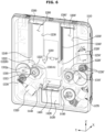
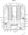
- FIG. 8 is a view illustrating a state in which some components of the automatic detergent dispenser of the dishwasher according to an embodiment are removed
- FIG. 9 is a view illustrating a state in which a solid detergent loaded in a first storage compartment is discharged from the first storage compartment of FIG. 8
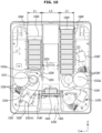
- FIG. 10 is a view illustrating a state in which the solid detergent of FIG. 9 is seated on a seating member
- FIG. 11 is a view illustrating a state in which the solid detergent of FIG. 10 is discharged from the automatic detergent dispenser
- FIG. 12 is a view illustrating a state in which a solid detergent loaded in a second storage compartment is discharged from the second storage compartment of FIG. 8 .
- control device 1900 may control the first ejector 1300 or the second ejector 1300' to allow one of the plurality of solid detergents stacked in one of the first storage compartment 1200 and the second storage compartment 1200' to be moved to the seating member 1400.
- control device 1900 may control the first ejector 1300 to be driven.
- the control device 1900 may control the first ejector 1300 to be driven again or control the second ejector 1300' to be driven based on the sensing value of the seating member sensor 1440. A description thereof will be described later in detail.
- control device 1900 may control the first ejector 1300 to allow the first cam member 1310 to be rotated clockwise.
- control device 1900 may control the second ejector 1300' to allow the second cam member 1310' to be rotated clockwise.
- the control device 1900 may control the position of the first cam member 1310 to allow the first cam region 1310A1 of the first cam member 1310 to be arranged at the upper end in the third direction Z before the first cam member 1310 is rotated and the first presser 1312a is moved into the storage compartment 1200.
- the first cam region 1310A1 of the first cam member 1310 When the first cam region 1310A1 of the first cam member 1310 is arranged at the upper end of the first cam member 1310 in the third direction Z, the first cam region 1310A1 may be disposed below the first support surface 1222 of the storage compartment 1200 in the third direction Z as described above. Accordingly, the solid detergent located at the lowest position in the third direction Z among the plurality of solid detergents loaded in the first storage compartment 1200 may be stably seated on the first support surface 1222, and thus the first presser 1312a may stably move the solid detergent to the second direction Y by the rotation of the first cam member 1310.
- the solid detergent located at the lowest position in the third direction Z among the plurality of solid detergents loaded in the first storage compartment 1200 may not be horizontally disposed in the third direction Z. Accordingly, when the solid detergent is moved in the second direction Y, the solid detergent may be rotated or moved to another direction without being moved to the second direction Y by the center of gravity. Accordingly, the solid detergent may not be moved toward the first storage compartment outlet 1210 and may not be discharged to the outside of the first storage compartment 1200.
- control device 1900 may control the position of the first cam member 1310 to allow the first cam region 1310A1 of the first cam member 1310 to be arranged at the upper end in the third direction Z when the dishwasher 1 does not performs the washing process. Thereafter, when the dishwasher 1 performs the washing process, the control device 1900 may communicate with the main control device and the control device 1900 may control the first ejector 1300 to allow the first cam member 1310 to be rotated clockwise based on a communication value.
- the first presser 1312a may be interlocked with the rotation of the first cam member 1310 and moved into the first storage compartment 1200, and accordingly, the solid detergent located at the lowest position in the third direction Z may be moved to the right side with respect to the second direction Y by the first presser 1312a.
- the solid detergent may be pressed by the first presser 1312a and moved to the first storage compartment outlet 1210, and while the solid detergent opens the first intermediate door 1250 provided to close the first storage compartment outlet 1210, the solid detergent may be discharged to the outside of the first storage compartment 1200 through the first storage compartment outlet 1210.
- the solid detergent may be disposed on the seating member 1400, particularly, on the seating member door 1410, as illustrated in FIG. 10 .
- the seating member sensor 1440 may detect the position of the solid detergent, that is, whether or not the solid detergent is located in the seating member inner space 1401. Particularly, the seating member sensor 1440 may be arranged on the seating member door 1410 in the third direction Z and configured to detect whether the solid detergent is located on the seating member door 1410.
- the control device 1900 may receive information on the position of the solid detergent located on the seating member door 1410 by the seating member sensor 1440 and communicate with the main control device, and the controller may control the dishwasher 1 to allow the dishwasher 1 to perform the washing process based on the communicated value.
- the washing process of the dishwasher 1 may be divided into the pre-washing operation, the main washing operation, the rinsing operation, and the drying operation.
- the controller may control the dishwasher 1 to allow the dishwasher 1 to perform the pre-washing operation based on the communicated value.
- the control device 1900 may transmit the information that no solid detergent is detected to the main control device.
- the controller may control the dishwasher 1 to allow the dishwasher 1 not to perform the pre-washing operation of the washing process based on the communicated value. This is because, in some cases, a user can open the door 20 to load the solid detergent into the automatic detergent dispenser 1000. Accordingly, the controller may control the dishwasher 1 not to start the washing process itself when no solid detergent is placed in the seating member 1400.
- the control device 1900 may additionally drive the first ejector 1300 once again, which is different from FIG. 10 .
- the controller may control the dishwasher 1 to allow the dishwasher 1 not to perform the washing process.
- control device 1900 may receive information on the position of the solid detergent located on the seating member door 1410 by the seating member sensor 1440 and communicate with the main control device, and the controller may control the dishwasher 1 to allow the dishwasher 1 to perform the washing process based on the communicated value.
- the control device 1900 may open the seating member door 1410 to allow the solid detergent to be discharged from the seating member inner space 1401 and to be input to the tub 12 through the discharge guide 1430.
- the solid detergent When the seating member door 1410 opens the seating member opening 1420, the solid detergent may be moved to the discharge guide 1430 through the seating member opening 1420, and the solid detergent may be discharged from the automatic detergent dispenser 1000 along the discharge guide 1430 through the inlet 1122.
- the seating member door 1410 may open the seating member opening 1420 while rotating downward, and the solid detergent placed on the seating member door 1410 may be moved to the discharge guide 1430 by passing through the seating member opening 1420 while the solid detergent is moved downward according to the rotation of the seating member door 1410.
- the control device 1900 may rotate the seating member door 1410 to allow the seating member door 1410 to open the seating member opening 1420, and after a predetermined time elapses, the control device 1900 may rotate the seating member door 1410 to the opposite direction to allow the seating member door 1410 to close the seating member opening 1420, again.
- control device 1900 may control opening and closing of the seating member door 1410.
- the control device 1900 may control the seating member door driver 1470 to open and close the seating member door 1410.
- the seating member door driver 1470 may transmit a rotational force, which is in one direction or the opposite direction, to the seating member door 1410 under the control of the control device 1900, so as to drive the seating member door 1410 to open and close the seating member opening 1420.
- control device 1900 may control the second ejector 1300' to be driven.
- the feature of driving the second ejector 1300' by the control device 1900 is the same as the feature of driving the first ejector 1300 by the control device 1900, and thus a description thereof will be omitted.
- the presser 1312a presses the solid detergent located at the lowest position among the plurality of solid detergents according to the rotation of the cam member 1310 and as the presser 1312a is moved out of the storage compartment 1200, the plurality of solid detergents in the stacked state may be moved downward with respect to the third direction Z.
- the plurality of solid detergents may be stacked and loaded in a direction different from the third direction Z that is a direction different from the vertical direction of the dishwasher 1, in the storage compartment 1200.
- the automatic detergent dispenser 1000 may include a storage compartment including a long side extending in the second direction Y, which is the left and right direction of the dishwasher 1.
- a plurality of solid detergents may be stacked and loaded in the second direction Y inside the storage compartment.
- the automatic detergent dispenser 1000 may include a holder configured to move the plurality of solid detergents, which is stacked in the second direction Y inside the storage compartment, to the second direction Y.
- the holder may include an elastic member, and thus the holder may move the plurality of solid detergents to the second direction Y toward a cam member of an ejector.
- the cam member may press one of the plurality of solid detergents to be discharged to the outside of the storage compartment.
- the solid detergent may be discharged to a direction perpendicular to the second direction Y and then moved to the lower side of the storage compartment.
- One solid detergent discharged to the outside of the storage compartment may be introduced into the tub 12 through a seating member or the like.
- the automatic detergent dispenser 1000 may include storage compartments 1200 and 1200' in which a plurality of solid detergents is stacked and loaded in the third direction Z, as illustrated in FIGS. 1 to 12 .
- the automatic detergent dispenser 1000 may be provided to allow a plurality of solid detergents to be moved upward in the storage compartments 1200 and 1200' and then discharged.
- the automatic detergent dispenser 1000 may include a holder arranged inside the storage compartments 1200 and 1200' and configured to move the plurality of solid detergents to the upper side.
- the holder may include an elastic member, and thus the holder may move the plurality of solid detergents to the upper side.
- a cam of an ejector may be disposed above the storage compartments 1200 and 1200', and one solid detergent disposed at the highest position among the plurality of solid detergents may be moved out of the storage compartment 1200 by the cam of the ejector.
- One solid detergent moved to the outside of the storage compartment 1200 may be introduced into the tub 12 through a seating member or the like.
- the stacking direction of the plurality of solid detergents is not limited by the term "third direction”.
- the stacking direction of the plurality of solid detergents may be referred to as a "first direction” as needed, and even in this case, the term “first direction” may represent the Z direction shown in the drawings according to an embodiment of the disclosure (it is assumed that the automatic detergent dispenser 1000 is at the first position 1000A) and the like.
- first direction may represent the Z direction shown in the drawings according to an embodiment of the disclosure (it is assumed that the automatic detergent dispenser 1000 is at the first position 1000A) and the like.
- the holder 1500 will be described in detail.
- a cross-sectional area of the storage compartment 1200 according to an example will be described in detail.
- FIG. 13 is a view illustrating a state in which some components of the automatic detergent dispenser of the dishwasher according to an embodiment are removed.
- the horizontal length L1 of the first storage compartment 1200 and a horizontal length L5 of the second storage compartment 1200' may be different from each other.
- the horizontal length L1 of the first storage compartment 1200 may be provided to have a predetermined length to allow the above-described solid detergent D to be stored in the storage compartment 1200.
- the horizontal length L5 of the second storage compartment 1200' may be less than the horizontal length L1 of the first storage compartment 1200.
- the horizontal length L5 of the second storage compartment 1200' may be greater than the horizontal length L1 of the first storage compartment 1200.
- the width L4 of the seating member 1400 in the second direction Y may be substantially similar to the width L1 of the first storage compartment 1200. This is because, when the solid detergent is discharged from the first storage compartment 1200 to the seating member 1400 in a state in which the width L4 of the seating member 1400 is excessively less than the width L5 of the second storage compartment 1200', the solid detergent may be stuck in the seating member inner space 1401 without being seated on the seating member door 1410.
- the width L4 of the seating member 1400 in the second direction Y is excessively greater than the width L1 of the first storage compartment 1200 or the width L5 of the second storage compartment 1200', the volume of the seating member 1400 in the second direction Y may increase more than necessary and thus the volume of the automatic detergent dispenser 1000 in the second direction Y may increase more than necessary.
- the width L4 of the seating member 1400 may have a length similar to the width L1 of the first storage compartment 1200 having a cross-sectional area S in accordance with the size of the solid detergent, in the second direction Y.
- a small solid detergent D' stored in the second storage compartment 1200' may be defined as a small solid detergent D' that has a smaller volume than the general solid detergent D and thus has a shorter horizontal length than the horizontal length d1 of the solid detergent D.
- the small solid detergent D' may be a solid detergent D' in a shape in which the general solid detergent D is partially cut in the direction of the horizontal length d1.
- the second storage compartment 1200' may be provided to store the small solid detergent D', which is different in volume from the solid detergent D. Accordingly, a user can selectively perform the washing process using the general solid detergent D or the small solid detergent D' as needed.
- a user can input information about the washing mode of the dishwasher 1 through the inputter of the dishwasher 1 or a mobile device to allow the dishwasher 1 to selectively perform one of a normal washing mode and a small amount washing mode.
- the control device 1900 may control the automatic detergent dispenser 1000 to drive the first ejector 1300 or the second ejector 1300' based on a user input obtained from the main control device.
- control device 1900 may control the automatic detergent dispenser 1000 to allow the first ejector 1300 to be driven.
- an adjusting member 1270 configured to adjust the cross-sectional area of the storage compartment 1200 according to an embodiment will be described in detail.
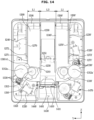
- FIG. 14 is a view illustrating a state in which some components of the automatic detergent dispenser of the dishwasher according to an embodiment are removed
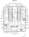
- FIG. 15 is a view illustrating a state in which an adjusting member of the second storage compartment is moved in FIG. 14 .
- the storage compartment 1200 may include the adjusting member 1270 configured to adjust an internal width of the storage compartment 1200.
- solid detergent D When the above-described solid detergent D is defined as a general solid detergent D that has an appropriate volume for washing in accordance with a capacity of the tub 12 of the general dishwasher 1 and has a predetermined horizontal length d1 according to the appropriate volume, some solid detergents D" may have a smaller volume than the general solid detergent D, and thus a width d1" of the solid detergents D" may be less than the width d1 of the general solid detergents D.
- the some solid detergents D" when the some solid detergents D" are stacked in the storage compartment 1200 having the width L1 corresponding to the width d1 of the general solid detergent D, the some solid detergents D" may be moved in the second direction Y due to a gap between the right surface 1230 or the left surface 1240 of the storage compartment 1200 and the some solid detergents D" in the storage compartment 1200, and thus some solid detergents D" may be separated from the stacked arrangement of the solid detergents D".
- the ejector 1300 When the ejector 1300 is driven in a state in which the some solid detergents D" are separated, the plurality of solid detergents D" may not be moved to the third direction Y by the ejector 1300 and the some solid detergents D" may be stuck in the storage compartment 1200 and thus may not be discharged to the outside of the storage compartment 1200.
- the storage compartment 1200 may include the adjusting member 1270 configured to adjust the width of the storage compartment 1200 in the second direction Y, and the adjusting member 1270 may be moved in the second direction Y so as to adjust the width of the storage compartment 1200.
- the adjusting member 1270 may adjust a width L6 of the storage compartment 1200 to correspond to the width d1" of the some solid detergent D", and thus the stacked state of the solid detergents D" may be maintained in the storage compartment 1200.
- the adjusting member 1270 may include a support wall 1271 provided to support a plurality of solid detergents and a mover 1272 connected to the support wall 1271 in the second direction Y so as to move a position of the support wall 1271 toward the second direction Y.
- the adjusting member 1270 may be disposed on the right surface 1230 or the left surface 1240 of the storage compartment 1200.
- the width L1 of the storage compartment 1200 may be approximately the same as the width d1 of the general solid detergent D.
- a user can adjust the width of the storage compartment 1200 by pressing the support wall 1271 toward the second direction Y.
- a user can move the support wall 1271, which is disposed adjacent to the right surface 1230 or the left surface 1240, toward the second direction Y so as to allow the width d1" of some solid detergents D" to correspond to the width L6 of the storage compartment 1200.
- the mover 1272 may be extended or contracted in the second direction Y to allow the support wall 1271 to be moved in the second direction Y inside the storage compartment 1200.
- the mover 1272 may be provided to be movable in the second direction Y between the outside and the inside of the storage compartment 1200 to allow the support wall 1271 to be moved in the second direction Y inside the storage compartment 1200.
- a user can open the storage compartment cover 1140 to open the storage compartment 1200 and move the adjusting member 1270 toward the second direction Y to have a width of the storage compartment 1200 that is desired by the user.
- a user can selectively adjust the width of the storage compartment 1200 by gripping the support wall 1271 and moving the support wall 1271 toward the second direction Y to form the width of the storage compartment 1200 desired by the user.
- the mover 1272 may be extended or contracted in the second direction Y.
- the adjusting member 1270 may be driven by the control of the control device 1900 by an adjusting member driver.
- a user can input information about the width of the storage compartment 1200 to the dishwasher 1 through the inputter of the dishwasher 1 or a mobile device, and the control device 1900 may control the adjusting member 1270 to move the mover 1272 or to expand or contract the mover 1272 so as to allow the adjusting member 1270 to be moved in the second direction Y by a predetermined distance based on the user input obtained from the main control device.
- the holder 1500 may be provided to move between the support wall 1271 and one surface, on which the adjusting member 1270 is not disposed, of the right surface 1230 or the left surface 1240.
- the guide rail 1290 provided to guide the movement of the holder 1500 may be disposed on the support wall 1271.
- the holder 1500 may be translated in the third direction Z by being guided by the guide rail 1290 disposed on the support wall 1271 and the guide rail disposed on one surface, on which the adjusting member 1270 is not disposed, of the right surface 1230 or the left surface 1240.
- the holder 1500 may be provided in a shape that is contracted in the second direction Y when the support wall 1271 is moved in a direction away from the right surface 1230 or the left surface 1240.
- the holder 1500 may be provided in a shape that is contracted or expanded in the second direction Y.
- the holder 1500 may be provided in a telescopic shape. Accordingly, when the support wall 1271 is moved toward the center of the storage compartment 1200, the holder 1500 may be overlapped and contracted, and when the support wall 1271 is moved in the opposite direction of the center direction of the storage compartment 1200, the holder 1500 may be expanded and extended.
- the adjusting member 1270 may include a first adjusting member 1270 provided inside the first storage compartment 1200 and a second adjusting member 1270' provided inside the second storage compartment 1200'.
- a user can adjust the width of the first storage compartment 1200 and the second storage compartment 1200' by moving the first adjusting member 1270 and the second adjusting member 1270', respectively.
- a user can maintain the width L1 of the first storage compartment 1200 and the second storage compartment 1200' by not moving both the first adjusting member 1270 and the second adjusting member 1270'.
- a user can adjust the widths of the first storage compartment 1200 and the second storage compartment 1200' by moving one of the first and second adjusting members 1270 and 1270'.
- first adjusting member 1270 may be disposed on the left surface 1240 of the first storage compartment 1200.
- the second adjusting member 1270' may be disposed on the right surface 1230' of the second storage compartment 1200'.
- the second adjusting member 1270' may be disposed on the left surface 1240' of the second storage compartment 1200'.
- the first adjusting member 1270 may be disposed on the right surface 1230 of the first storage compartment 1200.
- the adjusting member 1270 may be provided in only one of the first storage compartment 1200 and the second storage compartment 1200'.
- the adjusting member 1270 of the first storage compartment 1200 may be disposed adjacent to the left surface 1240 to allow the width L1 of the first storage compartment 1200 to correspond to the width d1 of the general solid detergent D, and the adjusting member 1270' of the second storage compartment 1200' may be moved in the second direction Y from the right surface 1230' to allow the width L6 of the second storage compartment 1200' to correspond to the width d1" of some solid detergent D".
- a user can load the general solid detergent D into the first storage compartment 1200 and load some solid detergent D" into the second storage compartment 1200'.
- the storage compartment 1200 may include an adjusting member detection sensor configured to detect a position of each of the support walls 1271 and 1271'.
- the adjusting member detection sensor may detect a position in which the support wall 1271 of the first storage compartment 1200 and the support wall 1271' of the second storage compartment 1200' are disposed, and the control device 1900 may be configured to recognize the type of solid detergent loaded in the first storage compartment 1200 and the type of the solid detergent loaded in the second storage compartment 1200' based on the detected value.
- the adjusting member detection sensor may measure a distance to a position of each of the support walls 1271 and 1271', or detect a distance to a position of each of the support walls 1271 and 1271' by detecting a distance in which each of the movers 1272 and 1272' is moved, extended or contracted.
- a user can input information about the washing mode of the dishwasher 1 through the inputter of the dishwasher 1 or a mobile device to allow the dishwasher 1 to selectively perform one of the normal washing mode and the small amount washing mode.
- the control device 1900 may control the automatic detergent dispenser 1000 to allow the first ejector 1300 or the second ejector 1300' to be driven based on the user input obtained from the main control device, and a value sensed by the adjusting member detection sensor.
- control device 1900 may control the automatic detergent dispenser 1000 to allow the first ejector 1300 to be driven.
- controller 1900 may control the automatic detergent dispenser 1000 to allow the second ejector 1300' to be driven.
- FIG. 16 is a control diagram of the dishwasher according to an embodiment.
- the dishwasher 1 may include the main body 10, the tub 12 provided inside the main body 10, the door 20 configured to open and close the tub 12, and the automatic detergent dispenser 1000 configured to input a solid detergent to the inside of the tub 12.
- the dishwasher 1 may further include an input device 80 arranged outside the main body 10 and configured to receive an input from a user and a controller 1600 configured to control the dishwasher 1 according to the input received by the input device 80.
- the input device 80 may be integrally provided with a display 81 to be described later to realize a touch screen, or may be provided in the form of a button, a touch pad, or a jog shuttle.
- the input device 80 may receive inputs of various operations related to the dish washing from a user.
- the controller 1600 may include at least one memory 1602 configured to store a program for performing an operation described later and at least one processor 1601 configured to execute the stored program.
- the dishwasher 1 may further include a storage compartment sensor 1270 provided in the storage compartment 1200 to detect the inside of the storage compartment 1200.
- a storage compartment sensor 1270 provided in the storage compartment 1200 to detect the inside of the storage compartment 1200.
- the embodiment of the dishwasher 1 does not necessarily include the storage compartment sensor 1270, it is possible to exclude the storage compartment sensor 1270 according to the implementation.
- the memory 1602 may store programs for controlling various components of the dishwasher 1 including the ejector 1300.
- the memory 1602 may include volatile memory such as Static Random Access Memory (S-RAM) and Dynamic Random Access Memory (D-Lab) for temporarily storing data.
- the memory 1602 may include a non-volatile memory such as a read only memory (ROM), an erasable programmable read only memory (EPROM), and an electrically erasable programmable read only memory (EEPROM) for long-term storage of data.
- ROM read only memory
- EPROM erasable programmable read only memory
- EEPROM electrically erasable programmable read only memory
- the at least one processor 1601 may control the ejector 1300 to discharge one solid detergent from the storage compartment 1200 when selection of a washing course is input through the input device 80.
- the processor 1601 may control the ejector 1300 to discharge one solid detergent from the storage compartment 1200.
- the ejector 1300 may include the cam member 1310 configured to move one solid detergent to the outside of the storage compartment 1200 through the rotation of the cam member 1310.
- the at least one processor 1601 may control the ejector 1300 to rotate the cam member 1310 to allow the solid detergent to be discharged from the storage compartment 1200.
- one solid detergent may be moved out of the storage compartment 1200, and finally, as shown in FIG. 10 , the solid detergent may be seated on the seating member 1400.
- the seating member 1400 may be a place where one solid detergent discharged from the storage compartment 1200 is seated, and the solid detergent moved from the storage compartment 1200 according to the rotation of the cam member 1310 may be seated on the seating member 1400.
- the seating member sensor 1440 may detect an object on the seating member 1400. Accordingly, the at least one processor 1601 may determine whether the solid detergent is seated on the seating member 1400 based on the output of the seating member sensor 1440 as shown in FIG. 10 .
- the at least one processor 1601 may rotate the cam member 1310 one more time when it is determined that the solid detergent is not seated on the seating member 1400 after the rotation of the cam member 1310.
- the at least one processor 1601 may determine again whether the solid detergent is seated based on the output of the seating member sensor 1440. Accordingly, when it is determined that the solid detergent is not seated on the seating member 1400, the at least one processor 1601 may allow a solid detergent to be discharged from the storage compartment 1200 by rotating the cam member 1310 one more time.
- the at least one processor 1601 may determine the presence or absence of solid detergent in the storage compartment 1200 by controlling the rotation of the cam member 1310.
- the at least one processor 1601 may determine the presence or absence of solid detergent in the storage compartment 1200 based on the output of the storage compartment sensor 1270.
- the storage compartment sensor 1270 may be a sensor configured to recognize the presence or absence of an object in the storage compartment 1200, and may employ at least one of various types of sensors such as an optical sensor, an ultrasonic sensor, an infrared sensor, or an image sensor.
- the dishwasher 1 may further include the display 81 and a speaker 82, and provide a visual notification through the display 81 or an audible notification through the speaker 82.
- FIG. 18 is a view illustrating a state in which the solid detergent is discharged from the automatic detergent dispenser according to an embodiment.
- the automatic detergent dispenser 1000 may further include the seating member door 1410 provided to input the solid detergent seated on the seating member 1400 into the tub 12.
- the at least one processor 1601 may input the solid detergent into the tub 12 by opening the seating member door 1410.
- washing of dishes may be performed through a process of the pre-washing operation, the main washing operation, the rinsing operation, and the drying operation.
- the at least one processor 1601 may open the seating member door 1410 and input a solid detergent to the tub 12 when the main washing operation starts.
- the seating member door 1410 may serve to separate the automatic detergent dispenser 1000 and the tub 12. When the seating member door 1410 is opened, hot and humid air in the tub 12 may flow into the automatic detergent dispenser 1000 and damage may occur to the solid detergent stored in the storage compartment 1200.
- the at least one processor 1601 may control the seating member door 1410 to be closed when a predetermined period of time elapses after opening the seating member door 1410.
- the predetermined period of time may mean a minimum time in which the solid detergent is stably input into the tub 12, and may be determined based on experiments, statistics, simulations, or theories.
- FIG. 19 is a view illustrating a state in which an error in discharging a solid detergent occurs.
- an error in discharging the solid detergent may occur, such as the solid detergent being stuck in the intermediate door 1250 or the like.
- the at least one processor 1601 may determine whether an error in discharging the solid detergent, such as the solid detergent being stuck, occurs based on the power consumption or the rotational speed of the motor inside the ejector 1300.
- the at least one processor 1601 may determine an error in discharging the solid detergent based on the output of the storage compartment sensor 1270.
- the at least one processor 1601 may determine that an error in discharging the solid detergent occurs when it is determined that the solid detergent is not seated on the seating member 1400 based on the detection result of the seating member sensor 1440 after the rotation of the cam member 1310, and when it is determined that a solid detergent is present in the storage compartment 1200 based on the output of the storage compartment sensor 1270.
- the solid detergent When the cam member 1310 is rotated once, the solid detergent may be discharged from the storage compartment 1200 and detected on the seating member 1400 in the normal operation. However, a solid detergent may be not detected on the seating member 1400 because the solid detergent is stuck.
- the solid detergent When a solid detergent is not present in the storage compartment 1200, the solid detergent may be not detected on the seating member 1400. Accordingly, when it is determined that solid detergent is present in the storage compartment 1200 based on the output of the storage compartment sensor 1270, the at least one processor 1601 may determine that an error in discharging the solid detergent occurs.
- the at least one processor 1601 may determine that an error in discharging the solid detergent, such as the solid detergent being stuck, occurs.
- the at least one processor 1601 may control the cam member 1310 to rotate in a reverse direction.
- the at least one processor 1601 may rotate the cam member 1310 in the reverse direction to allow the cam member 1310 to be positioned at an initial position based on the cam member 1310 sensor.
- the solid detergent that is stuck may be adjusted to be positioned in a normal position.
- FIG. 20 is a control diagram of the dishwasher according to an embodiment.
- the ejector may include the first ejector 1300 configured to discharge one of the plurality of solid detergents stacked in the first storage compartment 1200 to the seating member 1400, and the second ejector 1300' configured to discharge one of the plurality of solid detergents stacked in the second storage compartment 1200' to the seating member 1400.
- the first ejector 1300 may include the first cam member 1310
- the second ejector 1300' may include the second cam member 1310'.
- the at least one processor 1601 may determine whether a solid detergent is seated on the seating member 1400 based on the output of the seating member sensor 1440 arranged in the seating member 1400, and when it is determined that the solid detergent is not seated on the seating member 1400, the at least one processor 1601 may rotate the first cam member 1310 one more time in the forward direction.
- the notification may be visually provided through the display or aurally provided through the speaker.
- the at least one processor 1601 may generate a control signal to proceed with the main washing operation.
- the horizontal lengths of the first storage compartment 1200 and the second storage compartment 1200' may be formed differently or provided to be adjustable. Hereinafter an operation in this case will be described in detail.
- the first mode may refer to a mode requiring a general solid detergent, that is, a standard washing course.
- the second mode may refer to a mode requiring a small amount of solid detergent, that is, a small amount washing course or a quick washing mode.
- the at least one processor 1601 may rotate the first cam member 1310 in the forward direction to allow one solid detergent to be discharged from the first storage compartment 1200 in which the general solid detergents are stored.
- the at least one processor 1601 may rotate the second cam member 1310' in the forward direction to allow one solid detergent to be discharged from the second storage compartment 1200' when the selection of the second mode of the washing course is input through the input device.
- the at least one processor 1601 may rotate the second cam member 1310' in the forward direction to allow one solid detergent to be discharged from the second storage compartment 1200' in which the small solid detergents are stored.
- the at least one processor 1601 may rotate the second cam member 1310' one time in the forward direction to allow one solid detergent to be discharged from the second storage compartment 1200'.
- the first storage compartment 1200 when the first mode is selected, it is required for the first storage compartment 1200 to discharge a solid detergent. However, there may be a case in which a solid detergent is not present in the first storage compartment 1200. In this case, it is required to control the solid detergent to be discharged from the second storage compartment 1200'.
- the at least one processor 1601 may rotate the first cam member 1310 one more time in the forward direction.
- the at least one processor 1601 may determine that the solid detergent is not present in the first storage compartment 1200 and may rotate the second cam member 1310' one time in the forward direction to allow the solid detergent to be discharged from the second storage compartment 1200'.
- the at least one processor 1601 may rotate the second cam member 1310' one more time in the forward direction.
- FIG. 21 is a control diagram of the dishwasher according to an embodiment.
- the automatic detergent dispenser 1000 may further include the first adjusting member 1270 provided to adjust the horizontal length of the first storage compartment 1200 and the second adjusting member 1270' provided to adjust the horizontal length of the second storage compartment 1200'.
- a user can input information about the horizontal length of the storage compartment through the input device.
- information about a horizontal length of at least one of the first storage compartment 1200 and the second storage compartment 1200' may be input through the input device, and the at least one processor 1601 may control the first adjusting member 1270 or the second adjusting member 1270' to have a horizontal length corresponding to the information the horizontal length.
- the at least one processor 1601 may control the second adjusting member 1270' to allow the second storage compartment 1200' to have a horizontal length corresponding to the input information.
- small solid detergents may be stored in the second storage compartment 1200' to allow different sizes of solid detergents to be input according to the washing modes.
- FIGS. 22 and 23 are flowcharts of a control method of the dishwasher.
- the ejector 1300 may be controlled to discharge one solid detergent from the storage compartment 1200 (1603).
- the ejector 1300 may be controlled to discharge one solid detergent from the storage compartment 1200 for the washing (1603).
- the at least one processor 1601 may generate a control signal for providing a notification that there is no solid detergent stored in the storage compartment 1200 (1619).
- the at least one processor 1601 may open the seating member door 1410 so as to input the solid detergent to the tub 12 (1609).
- the at least one processor 1601 may control the seating member door 1410 to be closed (1613).
Landscapes
- Washing And Drying Of Tableware (AREA)
Applications Claiming Priority (2)
| Application Number | Priority Date | Filing Date | Title |
|---|---|---|---|
| KR1020220146530A KR20240064458A (ko) | 2022-11-04 | 2022-11-04 | 식기세척기 및 그 제어 방법 |
| PCT/KR2023/011722 WO2024096269A1 (fr) | 2022-11-04 | 2023-08-09 | Lave-vaisselle et son procédé de commande |
Publications (2)
| Publication Number | Publication Date |
|---|---|
| EP4582000A1 true EP4582000A1 (fr) | 2025-07-09 |
| EP4582000A4 EP4582000A4 (fr) | 2026-01-21 |
Family
ID=90926726
Family Applications (1)
| Application Number | Title | Priority Date | Filing Date |
|---|---|---|---|
| EP23885966.4A Pending EP4582000A4 (fr) | 2022-11-04 | 2023-08-09 | Lave-vaisselle et son procédé de commande |
Country Status (3)
| Country | Link |
|---|---|
| US (1) | US12582280B2 (fr) |
| EP (1) | EP4582000A4 (fr) |
| CN (1) | CN119907636A (fr) |
Families Citing this family (1)
| Publication number | Priority date | Publication date | Assignee | Title |
|---|---|---|---|---|
| CN119907636A (zh) * | 2022-11-04 | 2025-04-29 | 三星电子株式会社 | 洗碗机及其控制方法 |
Family Cites Families (43)
| Publication number | Priority date | Publication date | Assignee | Title |
|---|---|---|---|---|
| US5167350A (en) | 1988-05-02 | 1992-12-01 | Henkel Kommanditgesellschaft Aut Aktien | Detergent dispensing device |
| DE4344205A1 (de) * | 1993-12-23 | 1995-06-29 | Aweco Kunststofftech Geraete | Geschirrspülmaschine mit einer Reinigungsmittel-Dosiervorrichtung |
| US6701944B2 (en) | 2001-01-25 | 2004-03-09 | Unilever Home & Personal Care Usa, Division Of Conopco, Inc. | Detergent dispenser system |
| US7231928B2 (en) | 2003-05-20 | 2007-06-19 | Whirlpool Corporation | Household dishwasher with bulk wash aid dispenser |
| US7275552B2 (en) | 2003-12-13 | 2007-10-02 | Whirlpool Corporation | Dishwasher with bulk wash aid dispenser |
| US7896195B2 (en) | 2004-06-08 | 2011-03-01 | Ecolab Inc. | Tablet dispenser with isolated product hopper |
| US7097068B2 (en) | 2004-06-08 | 2006-08-29 | Ecolab Inc. | Tablet dispenser with isolated delivery sensor |
| KR20070024037A (ko) | 2005-08-25 | 2007-03-02 | 삼성전자주식회사 | 세제공급장치를 갖는 세탁기 |
| US20080276969A1 (en) | 2007-05-07 | 2008-11-13 | Whirlpool Corporation | Appliance with unique locking receptacles |
| ITMI20071667A1 (it) | 2007-08-10 | 2009-02-11 | Reckitt Benckiser Nv | Supporto di erogazione per un dispensatore di sostanze erogabili, in particolare agenti di lavaggio |
| US20090090401A1 (en) | 2007-10-05 | 2009-04-09 | Whirlpool Corporation | Appliance with Multiple Source Wash Aid Pump |
| GB0815006D0 (en) | 2008-08-16 | 2008-09-24 | Reckitt Benckiser Nv | Improvements to detergent delivery device |
| CN101744597B (zh) * | 2008-12-10 | 2011-12-14 | 松下电器产业株式会社 | 餐具清洗机 |
| CN102356025B (zh) * | 2009-04-17 | 2015-01-21 | 株式会社汤山制作所 | 药剂供给装置和药剂发放装置 |
| DE102010027994A1 (de) | 2010-04-20 | 2011-10-20 | Henkel Ag & Co. Kgaa | Dosiersystem zur Freisetzung von wenigstens drei unterschiedlichen Zubereitungen während eines Waschprogramms einer Waschmaschine |
| WO2013093148A1 (fr) | 2011-12-19 | 2013-06-27 | Sallo Kyra, S.L. | Dispositif doseur de détergent pour lave-vaisselle |
| US9861185B2 (en) | 2012-12-21 | 2018-01-09 | John Paul Southgate | Fastener-stick dispensers for field use |
| US9861258B2 (en) | 2013-03-15 | 2018-01-09 | Whirlpool Corporation | Dishwasher |
| US9717393B2 (en) * | 2014-06-12 | 2017-08-01 | Whirlpool Corporation | Household appliance with bulk unit-dose dispenser |
| DE102015222586A1 (de) | 2015-11-16 | 2017-05-18 | BSH Hausgeräte GmbH | Verfahren zum Betreiben einer Geschirrspülmaschine und Geschirrspülmaschine |
| DE102016225828A1 (de) | 2016-12-21 | 2018-06-21 | Henkel Ag & Co. Kgaa | Verfahren zur Dosierung von Reinigungsmitteln |
| US11089939B2 (en) | 2018-02-21 | 2021-08-17 | Midea Group Co., Ltd. | Dishwasher with detergent storage |
| US11284776B2 (en) * | 2018-12-22 | 2022-03-29 | Emz-Hanauer Gmbh & Co. Kgaa | Tablet dosing system and water-carrying domestic cleaning apparatus equipped therewith |
| CN109700410B (zh) | 2018-12-30 | 2020-09-08 | 佛山市顺德区美的洗涤电器制造有限公司 | 洗碗机自动投放装置及具有其的洗碗机 |
| US11497380B2 (en) | 2019-06-19 | 2022-11-15 | Midea Group Co., Ltd. | Detergent cartridge for a dishwasher incorporating detergent dispensing verification |
| US12268349B2 (en) * | 2019-07-09 | 2025-04-08 | Reckitt Benckiser (Brands) Limited | Dosing unit, water bearing household appliance and method |
| KR102124387B1 (ko) | 2019-08-27 | 2020-06-18 | 주식회사 티앤지 | 배터리의 냉각 판넬의 제조 방법 |
| CN211484457U (zh) | 2019-12-23 | 2020-09-15 | 江苏雷利电机股份有限公司 | 一种固体剂分配器 |
| CN111436874B (zh) * | 2020-03-05 | 2022-04-22 | 佛山市顺德区美的洗涤电器制造有限公司 | 控制方法、投放装置、门体组件、家用电器及存储介质 |
| WO2021174505A1 (fr) | 2020-03-05 | 2021-09-10 | 佛山市顺德区美的洗涤电器制造有限公司 | Procédé de commande, dispositif d'alimentation, ensemble porte, appareil électroménager et support de support |
| DE102020128650A1 (de) * | 2020-06-09 | 2021-12-09 | Emz-Hanauer Gmbh & Co. Kgaa | Haushalts-Geschirrspülmaschine und Dosiersystem hierfür |
| CN212679061U (zh) * | 2020-07-28 | 2021-03-12 | 江苏雷利电机股份有限公司 | 洗碗块投放系统 |
| DE102021110759A1 (de) | 2020-12-07 | 2022-06-09 | Emz-Hanauer Gmbh & Co. Kgaa | Dosierung eines Feststoff-Reinigungsmittels in einer Haushalts-Geschirrspülmaschine |
| EP4582001A4 (fr) * | 2022-11-04 | 2025-12-31 | Samsung Electronics Co Ltd | Lave-vaisselle |
| CN119816235A (zh) * | 2022-11-04 | 2025-04-11 | 三星电子株式会社 | 洗碗机 |
| CN120018804A (zh) * | 2022-11-04 | 2025-05-16 | 三星电子株式会社 | 洗碗机 |
| EP4582004A4 (fr) * | 2022-11-04 | 2026-01-21 | Samsung Electronics Co Ltd | Lave-vaisselle |
| EP4582005A4 (fr) * | 2022-11-04 | 2026-01-21 | Samsung Electronics Co Ltd | Lave-vaisselle |
| KR20240064461A (ko) * | 2022-11-04 | 2024-05-13 | 삼성전자주식회사 | 식기세척기 |
| CN119907636A (zh) * | 2022-11-04 | 2025-04-29 | 三星电子株式会社 | 洗碗机及其控制方法 |
| KR20240064459A (ko) * | 2022-11-04 | 2024-05-13 | 삼성전자주식회사 | 식기세척기 및 그 제어 방법 |
| KR20240064462A (ko) * | 2022-11-04 | 2024-05-13 | 삼성전자주식회사 | 식기세척기 |
| CN120076750A (zh) * | 2022-11-04 | 2025-05-30 | 三星电子株式会社 | 洗碗机 |
-
2023
- 2023-08-09 CN CN202380067485.3A patent/CN119907636A/zh active Pending
- 2023-08-09 EP EP23885966.4A patent/EP4582000A4/fr active Pending
- 2023-12-29 US US18/401,181 patent/US12582280B2/en active Active
Also Published As
| Publication number | Publication date |
|---|---|
| CN119907636A (zh) | 2025-04-29 |
| US20240148218A1 (en) | 2024-05-09 |
| EP4582000A4 (fr) | 2026-01-21 |
| US12582280B2 (en) | 2026-03-24 |
Similar Documents
| Publication | Publication Date | Title |
|---|---|---|
| US11266234B2 (en) | Sink | |
| US20240148224A1 (en) | Dishwasher | |
| US12582280B2 (en) | Dishwasher and control method thereof | |
| RU2498764C2 (ru) | Посудомоечная машина | |
| US20250241508A1 (en) | Dish washer | |
| US20250228425A1 (en) | Dishwasher | |
| US20250228424A1 (en) | Dish washer and control method thereof | |
| US12569110B2 (en) | Dishwasher | |
| US12593954B2 (en) | Dishwasher | |
| US12507861B2 (en) | Dishwasher | |
| US20240148227A1 (en) | Dishwasher | |
| US12551085B2 (en) | Dishwasher | |
| US20240366058A1 (en) | Dishwasher and control method therefor | |
| KR20240064458A (ko) | 식기세척기 및 그 제어 방법 | |
| JP6906623B2 (ja) | 食器洗浄機および食器洗浄方法 | |
| KR20240064455A (ko) | 식기세척기 | |
| KR20240064466A (ko) | 식기세척기 | |
| KR20240064463A (ko) | 식기세척기 | |
| KR20240064457A (ko) | 식기세척기 | |
| KR20240064464A (ko) | 식기세척기 | |
| KR20240064456A (ko) | 식기세척기 | |
| KR20240064465A (ko) | 식기세척기 |
Legal Events
| Date | Code | Title | Description |
|---|---|---|---|
| STAA | Information on the status of an ep patent application or granted ep patent |
Free format text: STATUS: THE INTERNATIONAL PUBLICATION HAS BEEN MADE |
|
| PUAI | Public reference made under article 153(3) epc to a published international application that has entered the european phase |
Free format text: ORIGINAL CODE: 0009012 |
|
| STAA | Information on the status of an ep patent application or granted ep patent |
Free format text: STATUS: REQUEST FOR EXAMINATION WAS MADE |
|
| 17P | Request for examination filed |
Effective date: 20250331 |
|
| AK | Designated contracting states |
Kind code of ref document: A1 Designated state(s): AL AT BE BG CH CY CZ DE DK EE ES FI FR GB GR HR HU IE IS IT LI LT LU LV MC ME MK MT NL NO PL PT RO RS SE SI SK SM TR |
|
| A4 | Supplementary search report drawn up and despatched |
Effective date: 20251222 |
|
| RIC1 | Information provided on ipc code assigned before grant |
Ipc: A47L 15/44 20060101AFI20251216BHEP |
|
| DAV | Request for validation of the european patent (deleted) | ||
| DAX | Request for extension of the european patent (deleted) |