EP4582034A1 - Dispositif d'agrafage de tissu de type à insertion - Google Patents
Dispositif d'agrafage de tissu de type à insertion Download PDFInfo
- Publication number
- EP4582034A1 EP4582034A1 EP22931714.4A EP22931714A EP4582034A1 EP 4582034 A1 EP4582034 A1 EP 4582034A1 EP 22931714 A EP22931714 A EP 22931714A EP 4582034 A1 EP4582034 A1 EP 4582034A1
- Authority
- EP
- European Patent Office
- Prior art keywords
- clamping
- arms
- moving member
- arm
- limiting
- Prior art date
- Legal status (The legal status is an assumption and is not a legal conclusion. Google has not performed a legal analysis and makes no representation as to the accuracy of the status listed.)
- Pending
Links
Images








Classifications
-
- A—HUMAN NECESSITIES
- A61—MEDICAL OR VETERINARY SCIENCE; HYGIENE
- A61B—DIAGNOSIS; SURGERY; IDENTIFICATION
- A61B17/00—Surgical instruments, devices or methods
- A61B17/12—Surgical instruments, devices or methods for ligaturing or otherwise compressing tubular parts of the body, e.g. blood vessels or umbilical cord
- A61B17/128—Surgical instruments, devices or methods for ligaturing or otherwise compressing tubular parts of the body, e.g. blood vessels or umbilical cord for applying or removing clamps or clips
- A61B17/1285—Surgical instruments, devices or methods for ligaturing or otherwise compressing tubular parts of the body, e.g. blood vessels or umbilical cord for applying or removing clamps or clips for minimally invasive surgery
-
- A—HUMAN NECESSITIES
- A61—MEDICAL OR VETERINARY SCIENCE; HYGIENE
- A61B—DIAGNOSIS; SURGERY; IDENTIFICATION
- A61B17/00—Surgical instruments, devices or methods
- A61B17/08—Wound clamps or clips, i.e. not or only partly penetrating the tissue ; Devices for bringing together the edges of a wound
- A61B17/083—Clips, e.g. resilient
-
- A—HUMAN NECESSITIES
- A61—MEDICAL OR VETERINARY SCIENCE; HYGIENE
- A61B—DIAGNOSIS; SURGERY; IDENTIFICATION
- A61B17/00—Surgical instruments, devices or methods
- A61B17/10—Surgical instruments, devices or methods for applying or removing wound clamps, e.g. containing only one clamp or staple; Wound clamp magazines
-
- A—HUMAN NECESSITIES
- A61—MEDICAL OR VETERINARY SCIENCE; HYGIENE
- A61B—DIAGNOSIS; SURGERY; IDENTIFICATION
- A61B17/00—Surgical instruments, devices or methods
- A61B17/12—Surgical instruments, devices or methods for ligaturing or otherwise compressing tubular parts of the body, e.g. blood vessels or umbilical cord
- A61B17/122—Clamps or clips, e.g. for the umbilical cord
-
- A—HUMAN NECESSITIES
- A61—MEDICAL OR VETERINARY SCIENCE; HYGIENE
- A61B—DIAGNOSIS; SURGERY; IDENTIFICATION
- A61B17/00—Surgical instruments, devices or methods
- A61B17/00234—Surgical instruments, devices or methods for minimally invasive surgery
- A61B2017/00292—Surgical instruments, devices or methods for minimally invasive surgery mounted on or guided by flexible, e.g. catheter-like, means
- A61B2017/003—Steerable
- A61B2017/00305—Constructional details of the flexible means
- A61B2017/00309—Cut-outs or slits
-
- A—HUMAN NECESSITIES
- A61—MEDICAL OR VETERINARY SCIENCE; HYGIENE
- A61B—DIAGNOSIS; SURGERY; IDENTIFICATION
- A61B17/00—Surgical instruments, devices or methods
- A61B17/00234—Surgical instruments, devices or methods for minimally invasive surgery
- A61B2017/00292—Surgical instruments, devices or methods for minimally invasive surgery mounted on or guided by flexible, e.g. catheter-like, means
- A61B2017/0034—Surgical instruments, devices or methods for minimally invasive surgery mounted on or guided by flexible, e.g. catheter-like, means adapted to be inserted through a working channel of an endoscope
-
- A—HUMAN NECESSITIES
- A61—MEDICAL OR VETERINARY SCIENCE; HYGIENE
- A61B—DIAGNOSIS; SURGERY; IDENTIFICATION
- A61B17/00—Surgical instruments, devices or methods
- A61B2017/00367—Details of actuation of instruments, e.g. relations between pushing buttons, or the like, and activation of the tool, working tip, or the like
- A61B2017/00398—Details of actuation of instruments, e.g. relations between pushing buttons, or the like, and activation of the tool, working tip, or the like using powered actuators, e.g. stepper motors, solenoids
-
- A—HUMAN NECESSITIES
- A61—MEDICAL OR VETERINARY SCIENCE; HYGIENE
- A61B—DIAGNOSIS; SURGERY; IDENTIFICATION
- A61B17/00—Surgical instruments, devices or methods
- A61B2017/0046—Surgical instruments, devices or methods with a releasable handle; with handle and operating part separable
- A61B2017/00473—Distal part, e.g. tip or head
-
- A—HUMAN NECESSITIES
- A61—MEDICAL OR VETERINARY SCIENCE; HYGIENE
- A61B—DIAGNOSIS; SURGERY; IDENTIFICATION
- A61B17/00—Surgical instruments, devices or methods
- A61B17/12—Surgical instruments, devices or methods for ligaturing or otherwise compressing tubular parts of the body, e.g. blood vessels or umbilical cord
- A61B2017/12004—Surgical instruments, devices or methods for ligaturing or otherwise compressing tubular parts of the body, e.g. blood vessels or umbilical cord for haemostasis, for prevention of bleeding
Definitions
- the present application relates to the field of medical instruments, particularly a structure of an insertion-type tissue-clamping device for surgery.
- An insertion-type tissue-clamping device is an insertion-type medical instrument for clamping tissue in a human or animal body to play a role of hemostasis or closure, which includes a hemostatic clamp, a tissue clamp, and the like.
- the tissue-clamping device is generally disposed in the instrument channel of an endoscope to realize therapeutic purposes.
- the hemostatic clamp or the tissue clamp
- the tissue clamp has been widely used for hemostasis or closure at the site of gastrointestinal bleeding or vulnus.
- a type of hemostatic clamp (or tissue clamp) is opened and clamped primarily by the cooperation between the clamp arms and the sleeve.
- the left and right clamp arms are loosely assembled together by a pin.
- the clamp arm assembly is pulled in a proximal direction, the clamp arms are gradually retracted into the sleeve and engaged with the front edge of the sleeve.
- the sleeve applies a reverse squeezing force to the clamping arms, which enables the clamping arms to be elastically deformed inward, thereby closing.
- the clamping arm assembly moves towards a distal direction, the clamping arms are pushed out of the sleeve and automatically reopens due to their elastic restoring force, thereby enabling the clamping device to be repeatedly opened and closed. Due to the utilization of the space in the axial direction of the sleeve, the structure realizes the closure of the clamping arms, and therefore a part of the clamping arms must be contracted in the sleeve, resulting in a long overall length retained in the patient's body after the hemostatic clamp is separated, which is prone to cause damage and discomfort to the patient.
- the clamping arms are connected mainly by a rotating shaft, an up-and-down sliding track is disposed in the sleeve, and the shaft can slide along the track.
- the upper end of the sleeve is also provided with a fixed shaft, the clamping arm is provided with a long strip-shaped hole, and the fixing shaft extends through the long strip-shaped hole of the clamping arm.
- This structure improves operation precision and reduces the size of the clamp, but with more parts, a complicated structure, and a high cost.
- the overall length of the clamp is still large under the premise of the same opening width.
- the overall size of the clamp is still long, which is not conducive to passing through the instrument channel of the endoscope, and leads to an obvious foreign body sensation when the whole clamp stays in the human body.
- the present application provides an insertion-type tissue clamping device to demonstrate a new opening and clamping structure.
- an insertion-type tissue clamping device including:
- the clamping member includes a support arm located between the clamping arms, and the support arm is provided with a limiting member; when the moving member moves to a back end, the limiting member is located on a movement path of the rocker arms, and the limiting member is configured to contact at least one rocker arm and form a fulcrum of a lever structure for the at least one rocker arm.
- At least two rocker arms are arranged in an intersection-shape, and the limiting member is located in an intersection region formed by the two rocker arms and adjacent to the moving member, such that when the moving member moves to the back end, the limiting member forms the fulcrum of the lever structure for the at least one rocker arm.
- a lever arm of a rotational center of the rocker arm relative to the moving member from a center of the limiting member is longer than a lever arm of a connection center between the rocker arm and the clamping head from the center of the limiting member.
- the two rocker arms have locking fitting surfaces, when the clamping arms are in the clamping state, the locking fitting surfaces of the two rocker arms enclose a locking groove, and the limiting member is located in the locking groove to prevent the two clamping arms from cross moving transversely, so as to maintain the clamping arms in the clamping state.
- the two rocker arms have guide surfaces.
- the guide surfaces enclose a guide space.
- the limiting member is provided in the guide space, and the guide space is in communication with the locking groove to guide the locking groove to be engaged with the limiting member when the rocker arms drive the clamping arms to move to be in the clamping state.
- a front end of the moving member has a limiting structure, when the clamping arms are in the opening state, the limiting structure forms a limitation on a back side of the limiting member to prevent the moving member from continuing to move towards a front end, so as to limit an opening angle of the clamping arms.
- a front end of the rocker arm away from a corresponding clamping arm has a concave portion, and the concave portion is configured to avoid a tissue clamped by the clamping heads.
- one of the moving member and the rocker arm has a rotating shaft, and another one has a self-adjusting groove, the rotating shaft is provided in the self-adjusting groove, and the rotating shaft and the self-adjusting groove are capable of adaptively adjusting relative positions of the moving member and the rocker arm in a transverse direction during movement of the rocker arm.
- At least one support arm has a limiting guide portion provided along a longitudinal direction thereof, the moving member has at least one limiting guide engaging portion, and the limiting guide engaging portion is engaged with the limiting guide portion to prevent the moving member from moving along a direction defined by the limiting guide portion.
- the limiting member has two limiting blocks provided in an axial direction thereof.
- a limiting space is formed between the two limiting blocks.
- the two rocker arms are stacked in the limiting space in the axial direction of the limiting member to prevent the two rocker arms from disengaging along the axial direction of the limiting member.
- the bendable portion has at least one deformable portion, when the clamping arms are in the clamping state, the deformable portion is capable of being extruded inwardly and deformed, so as to drive the clamping arms as a whole to move towards a back end of the insertion-type tissue clamping device.
- the clamping member has a locking engaging portion
- the moving member has a locking portion; when the clamping arms are separated from the transmission member, the locking portion and the locking engaging portion are locked to prevent the moving member and the rocker arms from moving towards the front end of the clamping member and prevent the clamping arms from opening.
- the locking portion is an engaging platform provided on the moving member
- the locking engaging portion is an elastic buckle extending inwardly
- the elastic buckle is provided in a path in which the engaging platform moves towards the back end, when the clamping arms are separated from the transmission member, the elastic buckle abuts against a front side of the engaging platform to prevent the engaging platform from moving towards the front end of the clamping member.
- a front end of the transmission member has a first snap portion
- a back end of the moving member has a second snap portion
- the first snap portion is snap-fitted with the second snap portion, at least one of the first snap portion and the second snap portion is of a deformable structure
- the deformable structure is capable of deforming under the pulling force of the transmission member, such that the first snap portion is disengaged from the second snap portion, and the moving member is separated from the transmission member.
- the clamping head and the bendable portion remain relatively fixed to each other, and the opening and closing of the clamping heads is achieved by the bending function of the bendable portion.
- the moving member is located in the clamping member in such a way that the moving member can move in the axial direction of the clamping member.
- the sleeve in the existing structure can be omitted, the clamping arms can be directly driven by the moving member, which combines the deformation state of the bendable portion to realize the opening and closing of the clamping arms.
- the length of the clamping arms is shorter than that of the combination of the clamping arms and the sleeve in the prior art.
- the limiting member is further included.
- the limiting member When the moving member moves to the back end, the limiting member is located on the movement path of the rocker arms to contact at least one rocker arm and form a fulcrum of a lever structure for the rocker arm. Through the function of the lever structure, the clamping arms can clamp the target tissue in the clamping state more firmly.
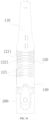
- the number of the first shrinkage slit groups 121 is in a range from 6 to 10
- the second shrinkage slit groups 122 are distributed at both ends of the bendable portion 120, so that the number of the second shrinkage slit groups 122 is one more than that of the first shrinkage slit groups 121, and the number is in a range from 7 to 11.
- the bendable portion 120 can be easily bent, and the strength can be ensured, avoiding that the bendable portion 120 is too soft to support the clamping head 110.
- the number of the second shrinkage slit groups 122 is 8, and the number of the first shrinkage slit groups 121 is 7.
- the first shrinkage slit 1211 and the second shrinkage slit 1221 can be provided in a non-parallel arrangement in addition to being parallel to each other.
- the bending deformation direction of each of the first shrinkage slits 1211 can be consistent, so that the bending deformation of the clamping member 1 can be more smooth and stable.
- the first shrinkage slit 1211 has a gap along the longitudinal direction of the bendable portion 120.
- the first shrinkage slit 1211 is a long strip-shaped slot, and has two opposite convex arc-shaped edges at the middle portion of the first shrinkage slit 1211. When the clamping member 1 is opened to the limiting position, the arc-shaped edges can contact each other, thus determining the maximum angle of opening.
- the second shrinkage slit 1221 is provided in a straight-line shape in the circumferential direction. In some other embodiments, the second shrinkage slit 1221 can also be provided in other shapes.
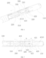
- the moving member 410 needs to move to a predetermined locking position together with the clamping arms 100 for locking, that is, the engaging platform 4122 needs to move to a position corresponding to the elastic buckle 330 for locking.
- the hardness or thickness of the human tissue clamped by the clamping member 1 varies (as shown in FIG. 22 ), which affects the closing angle of the clamping member 1. Since that closing angle is associate with the stroke of the moving member 410, the moving member 410 cannot move to the locking position, and the clamping arm 100 cannot be maintained in the clamping state.
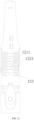
- the bendable portion 120 has a ring-shaped deformation portion 123.
- the clamping arms 100 are in the clamping state, if a larger target tissue 2 is clamped, it is difficult for the clamping arms 100, the moving member 410, and the rocker arms 420 to move to a position where self-locking with the limiting member 310 and locking with the locking engaging portion can be realized.
- the deformation portion 123 can be extruded inwardly and deformed to drive the clamping arms 100, the moving member 410, and the rocker arms 420 as a whole to move towards the back end of the insertion-type tissue clamping device relative to the supporting portion and the limiting member 310, so that self-locking of the rocker arms 420 and the limiting member 310 and locking of the moving member 410 and the locking engaging portion are realized.
- a gap is provided between the deformation portion 123 and the support arms 300, so that an avoiding empty area is formed on the outer periphery of the deformation portion 123, thereby facilitating deformation.
- the clamping arms 100 when the clamping arms 100 clamp a thinner target tissue 2, the clamping arms 100 can be closed normally, the deformation portion 123 maintains a normal gap, and the moving member 410 and the clamping arms 100 can accurately move to the position of the locking structure as described above, and the clamping arms 100 can be locked in the clamping state.
- the clamping arms 100 when the clamping arms 100 clamp a thicker target tissue 2, the clamping arms 100 cannot be closed to the extent shown in FIG. 20 .
- the force is continuously applied to the moving member 410, and when the operator intentionally applies an enhanced force, the deformation portion 123 is greatly deformed, thereby compensating for the lost stroke on the clamping arms 100 and the moving member 410, so that the clamping arms 100 can finally be locked to the locking structure.
- the deformation portion 123 provides an adaptive stroke range for the moving member 410 under different opening states of the clamping arm 100, generates a large deformation amplitude after receiving a specific pull-down force, always allows the elastic buckle 330 to be accurately and reliably locked, and allows the rocker arms 420 and the limiting member 310 to realize self-locking.
- the first shrinkage slit group 121 and the second shrinkage slit group 122 are provided on the front side of the deformation portion 123.
- the twisted deformation section 124 is connected to the front portion of the deformation portion 123, that is, the upper wall of the deformation portion 123 is connected to the twisted deformation section 124 of the clamping arm 100.
- the lower wall of the deformation portion 123 is connected to a connecting portion 140 (described in detail later), and the deformation portion 123 forms a gap with the support arm 300 in the transverse direction to avoid interference.
- the deformation amplitude of the deformation portion 123 can be determined according to the difference between the actual stroke and the desired stroke between the rocker arm 420 and the limiting member 310 when the clamping arms 100 clamp the large target tissue 2, that is, as shown in FIG. 23 , the distance between the rocker arms 420 and the limiting member 310 and the locking and self-locking position determines the deformation size of the deformation portion 123.
- the deformation portion 123 has a maximum distance a of being extruded inwardly and deformed in a range of 0.1 mm ⁇ a ⁇ 1.0 mm, for example, from 0.3 mm to 0.8 mm.
- the deformation 123 is of an elliptical structure.
- the deformation portion 123 can also be of other shapes, such as a circular structure or a diamond structure.
- the above-described embodiment shows a structure in which the bendable portion 120 realizes bending deformation by providing the first shrinkage slit group 121, the second shrinkage slit group 122, and the twisted deformation section 124.
- the structure of the bendable portion 120 in the present embodiment is not limited to this, and can be realized by other means.
- the thickness of the bendable portion 120 can also be set to be thinner than those of other portions, for example, thinner than those of the clamping head 110 and the connecting portion 140, so that the bendable portion 120 can preferentially bend and deform when the moving member 410 drives the clamping arm 100 to move.
- first stroke, the second stroke, and the third stroke are three parts of the entire movement stroke of the transmission member 510.
- the three strokes can be in the same direction, or at least two strokes can be in different directions.
- the strokes can be completely separated, completely unrelated, or at least two strokes can be continuous or overlapped, for example, the third stroke can closely follow the second stroke.
- the second stroke and the third stroke can also be two separate, non-continuous parts.
- the transmission member 510 is in the third stroke.
- the third stroke is in the same direction as and closely connected to the second stroke. That is, when the clamping arms 100 move to the clamping state, the transmission member 510 is switched from the second stroke to the third stroke.
- the third stroke can be divided into a plurality of sub-strokes including a locking stroke, an inner disengagement stroke, and an outer disengagement stroke.
- the transmission member 510 when the transmission member 510 is switched to the third stroke until it moves to the position shown in the figure, the clamping arms 100 are locked, and the transmission member 510 cannot move in the opposite direction and reopen the clamping arms 100. During this process, the movement stroke of the transmission member 510 is the locking stroke.
- the transmission member 510 enters the outer disengagement stroke after completing the inner disengagement stroke.
- the clamping arms 100 are disengaged from the separate base 200, so that the clamping arms 100 are left on the target tissue 2 clamped by the clamping arm 100.
- the separate base 200 and the transmission member 510 can be withdrawn from the patient.
- the movement stroke of the transmission member 510 is the outer disengagement stroke.
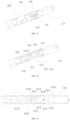
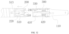
- FIGs. 13 to 18 and FIGs. 27 to 32 only show one embodiment of the third stroke in which the separation of the clamping arms 100 from the transmission member 510, and the disengagement of the clamping arms 100 from the separate base 200 can be achieved simultaneously, or either action can be achieved before the other.
- the locking stroke, the inner disengagement stroke, and the outer disengagement stroke can also be performed concurrently, for example, the inner disengagement stroke and the outer disengagement stroke overlap, and the inner disengagement and the outer disengagement are performed synchronously.
- the present application provides an example in which the front end of the transmission member 510 has a first snap portion and the back end of the moving member 410 has a second snap portion.
- the first snap portion is snap-fitted with the second snap portion.
- At least one of the first snap portion and the second snap portion is of a deformable structure.
- the deformable structure refers to a structure that can be deformed only when the pulling force reaches a set value, and the structure can be realized by material and structural design, for example, the deformable structure is made of an elastic material.
- One of the first snap portion and the second snap portion is a deformable connecting portion and the other is a fitting engaging groove, and the deformable connecting portion is snap-fitted in the fitting engaging groove.
- the deformable connecting portion 511 is provided on the transmission member 510, and the fitting engaging groove 413 (which may be a through hole or a blind hole) is provided at the bottom of the moving member 410.
- the shape of the fitting engaging groove 413 is matched with the shape of the deformable connecting portion 511 to engage the deformable connecting portion 511.
- the deformable connecting portion 511 includes at least one deformable hook that is connected in a corresponding fitting engaging groove 413.
- the deformable hook can be pulled to deform and thus disengage from the fitting engaging groove 413.
- the middle of the back end of the transmission member 510 can have a long slot, through which a limitation pin extends, and the bottom is cylindrical and connected to the pulling member (such as a pulling rope).
- the pulling member such as a pulling rope.
- the clamping arms 100 includes the connecting portion 140.
- the connecting portion 140 is provided on the back side of the bendable portion 120.
- the connecting portion 140, the bendable portion 120, the clamping head 110, and the support arm 300 are integrally formed.
- the connecting portion 140 is configured to connect the entire bendable portion 120, the clamping head 110, and the support arm 300 to the separate base 200.
- the separate base 200 and the connecting portion 140 can be integrally formed, or can be fixedly connected to each other after being manufactured separately.
- the separate base 200 is rotatably connected to the sleeve assembly 520, so that the clamping member 1 can rotate relative to the sleeve assembly 520 as a whole.
- the clamping arms 100 and the support arms 300 are integrally connected to the separate base 200 by the first tearing portion 210.
- the separate base 200 and the other parts of the clamping member 1 are integrally formed, and both are integrally connected by the first tearing portion 210. Additionally, the separate base 200 and other parts of the clamping member 1 can be connected as a whole by engagement or the like.
- the separate base 200 has a following member 220.
- the following member 220 is configured to receive an external force to drive the separate base 200 to separate from other parts of the clamping member 1 at the position of the first tearing portion 210.
- an external force applied by the operator can be transmitted to the first tearing portion 210 through a moving member 410 or other components.
- the following member 220 is driven to move by a moving member 410.
- the following member 220 is located on the moving trajectory of the moving member 410.
- the moving member 410 moves to the position of the following member 220, it drives the following member 220 to move together towards the control handle 3, so that the separate base 200 is separated from the connecting portion 140 and the like at the position of the first tearing portion 210 by the action of the moving member 410.
- At least one first tearing portion 210 is provided, and the end of the entirety of the clamping arms 100 and the support arms 300 opposite to the separate base 200 has a concave region 150.
- the concave region 150 is provided on the connecting portion 140.
- the first tearing portion 210 is provided in the concave region 150.
- the separate base 200 is connected to the clamping arms 100 and the support arms 300 only by the first tearing portion 210. This design enables the tearing surface of the first tearing portion 210 to be accommodated in the concave region 150 after the fracture of the first tearing portion 210, thereby avoiding exposure of sharp burrs after the fracture and avoiding damage to the surgical object.
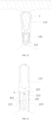
- the separate base 200 includes a cylindrical main body 230 and a suspension portion 240.
- the side wall of the body 230 has a suspension cavity 231.
- the suspension portion 240 is provided in the suspension cavity 231.
- the suspension portion 240 is aligned with and connected to the first tearing portion 210.
- the suspension portion 240 is provided with the above-described following member 220.
- the following member 220 is a limiting shaft fixedly attached to the suspension portion 240, and the limiting shaft traverses the suspension portion 240.
- the following member 220 is configured to drive the suspension portion 240 and the transmission member 510 to move to the back end when the transmission member 510 moves along the third stroke.
- Both sides of the suspension portion 240 are connected to the main body 230 by suspension arm 241, so that the suspension portion 240 can be deformed with respect to the main body 230 to tear the first tearing portion 210.
- the moving member 410 may also be provided with a limiting groove 513 disposed in the axial direction thereof.
- the following member 220 is disposed in the limiting groove 513.
- the top of the limiting groove 513 moves to the following member 220, thereby driving the following member 220 and the suspension portion 240 to move towards the control handle 3, thereby enabling the separate base 200 to separate from the connecting portion 140.
- the width of the first tearing portion 210 can be reserved according to needs, and a plurality of first tearing portions 210 can be provided according to functional needs, so that the structure can be more reliable and stable.
- first tearing portions 210 and at least two suspension portions 240 are provided.
- the first tearing portions 210 are distributed along the circumferential direction of the separate base 200.
- Each first tearing portion 210 is correspondingly provided with one suspension portion 240.
- Uniform distribution means that adjacent first tearing portions 210 or suspension portions 240 are spaced apart by the same distance or angle.
- the following member 220 can also function as a stroke limit for the moving member 410 to limit the movement of the moving member 410 within a set range, so as to define the limit stroke of the moving member 410 towards the front end, thus defining the opening stroke of the clamping member 1.
- the following member 220 blocks the transmission member 510, thereby defining the forward movement of the moving member 410 and the opening stroke of the clamping member 1.
- both sides of the suspension portion 240 are connected to the main body 230 by suspension arms 241, so that the suspension portion 240 can be more easily deformed relative to the main body 230.
- the entire separate base 200 cannot move to the control handle 3 alone under the support of the sleeve assembly 520.
- the moving member 410 pulls the suspension portion 240
- the main body 230 of the separate base 200 remains stationary, and the suspension arm 241 of the suspension portion 240 is deformed by the pulling force of the moving member 410.
- the main body 230 of the separate base 200 forms a opposite support for the clamping arms 100 and the like, and the materials of the suspension arm 241 and the first tearing portion 210 are gradually elongated.
- FIGs. 30 to 32 when the yield limit is reached, fracture occurs, and the suspension portion 240 is disengaged from the connecting portion 140. Thereafter, the separate base 200 can be removed from the body of the surgical subject together with the transmission assembly 5.
- the suspension cavity 231 has a guide groove 232 disposed in the axial direction of the separate base 200, and the suspension portion 240 is disposed in the guide groove 232 to guide the movement of the suspension portion 240 into the guide groove 232.
- the guide groove 232 defines a guide direction that is aligned with the first tearing portion 210, thereby allowing the suspension portion 240 to break from the first tear portion 210 more easily.
Landscapes
- Health & Medical Sciences (AREA)
- Life Sciences & Earth Sciences (AREA)
- Surgery (AREA)
- Molecular Biology (AREA)
- Engineering & Computer Science (AREA)
- Biomedical Technology (AREA)
- Heart & Thoracic Surgery (AREA)
- Medical Informatics (AREA)
- Nuclear Medicine, Radiotherapy & Molecular Imaging (AREA)
- Animal Behavior & Ethology (AREA)
- General Health & Medical Sciences (AREA)
- Public Health (AREA)
- Veterinary Medicine (AREA)
- Reproductive Health (AREA)
- Vascular Medicine (AREA)
- Surgical Instruments (AREA)
Applications Claiming Priority (1)
| Application Number | Priority Date | Filing Date | Title |
|---|---|---|---|
| PCT/CN2022/116302 WO2023173693A1 (fr) | 2022-08-31 | 2022-08-31 | Dispositif d'agrafage de tissu de type à insertion |
Publications (2)
| Publication Number | Publication Date |
|---|---|
| EP4582034A1 true EP4582034A1 (fr) | 2025-07-09 |
| EP4582034A4 EP4582034A4 (fr) | 2025-10-22 |
Family
ID=88022209
Family Applications (1)
| Application Number | Title | Priority Date | Filing Date |
|---|---|---|---|
| EP22931714.4A Pending EP4582034A4 (fr) | 2022-08-31 | 2022-08-31 | Dispositif d'agrafage de tissu de type à insertion |
Country Status (5)
| Country | Link |
|---|---|
| EP (1) | EP4582034A4 (fr) |
| JP (1) | JP2025529204A (fr) |
| KR (1) | KR20250048081A (fr) |
| CN (1) | CN117255655A (fr) |
| WO (1) | WO2023173693A1 (fr) |
Families Citing this family (2)
| Publication number | Priority date | Publication date | Assignee | Title |
|---|---|---|---|---|
| CN115399831B (zh) * | 2022-08-31 | 2025-07-22 | 宁波新跃医疗科技股份有限公司 | 插入式组织夹闭装置 |
| CN117838336B (zh) * | 2024-01-25 | 2024-08-27 | 瀚芯医疗科技(深圳)有限公司 | 组织限位装置 |
Family Cites Families (17)
| Publication number | Priority date | Publication date | Assignee | Title |
|---|---|---|---|---|
| US6036706A (en) * | 1998-03-13 | 2000-03-14 | Cardiothoracic Systems, Inc. | Vascular clamp and method for using the same |
| US7094245B2 (en) * | 2001-10-05 | 2006-08-22 | Scimed Life Systems, Inc. | Device and method for through the scope endoscopic hemostatic clipping |
| JP4412943B2 (ja) * | 2003-08-20 | 2010-02-10 | Hoya株式会社 | 内視鏡用クリップ装置 |
| EP2101653B1 (fr) * | 2006-12-05 | 2016-02-17 | Cook Medical Technologies LLC | Pince hémostatique de thérapie combinée |
| CN101836881B (zh) * | 2010-04-26 | 2011-07-20 | 南京思维斯精密机械制造有限公司 | 套筒结构式医用体内微创取物钳 |
| EP2651316B1 (fr) * | 2010-12-15 | 2016-07-06 | Cook Medical Technologies LLC | Dispositifs médicaux à mâchoires pivotantes détachables |
| US20150257756A1 (en) * | 2014-03-13 | 2015-09-17 | Lsi Solutions, Inc. | Surgical clamping device and methods thereof |
| CN110621240B (zh) * | 2017-06-21 | 2022-09-20 | 富士胶片株式会社 | 夹具处置器具 |
| CN111163711B (zh) * | 2017-11-28 | 2023-09-08 | 波士顿科学国际有限公司 | 用于可重新装载的止血夹装置的自对齐拉线 |
| CN110464410B (zh) * | 2019-07-03 | 2024-05-10 | 安瑞医疗器械(杭州)有限公司 | 配合内窥镜使用的夹子装置及其夹持部 |
| CN214712491U (zh) * | 2020-11-24 | 2021-11-16 | 宁波新跃医疗科技股份有限公司 | 蛇骨管 |
| CN114795367A (zh) * | 2021-01-27 | 2022-07-29 | 上海纽脉医疗科技有限公司 | 一种组织夹持装置及组织修复设备 |
| CN113662613A (zh) * | 2021-10-21 | 2021-11-19 | 北京迈迪顶峰医疗科技股份有限公司 | 钳式执行器以及输送装置 |
| CN115281774B (zh) * | 2022-03-21 | 2025-06-06 | 宁波新跃医疗科技股份有限公司 | 插入式夹持器械及其运动件 |
| US20250204913A1 (en) * | 2022-03-21 | 2025-06-26 | Ningbo Xinwell Medical Technology Co., Ltd | Insertable gripping instrument and gripper therefor |
| CN217853154U (zh) * | 2022-03-21 | 2022-11-22 | 宁波新跃医疗科技股份有限公司 | 插入式组织夹闭装置 |
| CN114767199A (zh) * | 2022-03-23 | 2022-07-22 | 深圳市赛诺思医疗科技有限公司 | 夹具输送装置 |
-
2022
- 2022-08-31 CN CN202280024123.1A patent/CN117255655A/zh active Pending
- 2022-08-31 EP EP22931714.4A patent/EP4582034A4/fr active Pending
- 2022-08-31 WO PCT/CN2022/116302 patent/WO2023173693A1/fr not_active Ceased
- 2022-08-31 KR KR1020257007584A patent/KR20250048081A/ko active Pending
- 2022-08-31 JP JP2025512970A patent/JP2025529204A/ja active Pending
Also Published As
| Publication number | Publication date |
|---|---|
| JP2025529204A (ja) | 2025-09-04 |
| CN117255655A (zh) | 2023-12-19 |
| EP4582034A4 (fr) | 2025-10-22 |
| WO2023173693A1 (fr) | 2023-09-21 |
| KR20250048081A (ko) | 2025-04-07 |
Similar Documents
| Publication | Publication Date | Title |
|---|---|---|
| US10130373B2 (en) | Automatic surgical ligation clip applier | |
| JP5848827B2 (ja) | 手動外科用結紮クリップアプライヤ | |
| US20250204913A1 (en) | Insertable gripping instrument and gripper therefor | |
| EP4582034A1 (fr) | Dispositif d'agrafage de tissu de type à insertion | |
| EP4582035A1 (fr) | Dispositif d'agrafage de tissu de type à insertion et bras oscillants associés | |
| EP4582032A1 (fr) | Dispositif d'agrafage de tissu de type à insertion et ensemble de commande de mouvement associé | |
| CN219397432U (zh) | 插入式组织夹闭装置 | |
| CN219397431U (zh) | 插入式组织夹闭装置及其内脱离结构 | |
| CN117062574A (zh) | 一体式夹持件的制造方法 | |
| JP2010011973A (ja) | 連発式クリップ処置具 | |
| CN117098503A (zh) | 插入式组织夹闭装置及其夹持件 | |
| US9730718B2 (en) | Medical device with quick-release mechanism | |
| US20250195079A1 (en) | Integrated gripper and manufacturing method | |
| CN115486892A (zh) | 插入式组织夹闭装置及其内脱离结构 | |
| WO2022257540A1 (fr) | Appareil de serrage de tissu insérable et pièce de préhension associée | |
| CN115399831B (zh) | 插入式组织夹闭装置 | |
| CN115444491B (zh) | 夹闭组件及内窥镜用止血装置 | |
| EP4245228A1 (fr) | Clips hémostatiques et dispositif de clippage de tissu | |
| HK40100786A (en) | Hemostatic clips and tissue clipping device | |
| CN113425348A (zh) | 夹头分体式缝合线锁结装置 |
Legal Events
| Date | Code | Title | Description |
|---|---|---|---|
| STAA | Information on the status of an ep patent application or granted ep patent |
Free format text: STATUS: THE INTERNATIONAL PUBLICATION HAS BEEN MADE |
|
| PUAI | Public reference made under article 153(3) epc to a published international application that has entered the european phase |
Free format text: ORIGINAL CODE: 0009012 |
|
| STAA | Information on the status of an ep patent application or granted ep patent |
Free format text: STATUS: REQUEST FOR EXAMINATION WAS MADE |
|
| 17P | Request for examination filed |
Effective date: 20250319 |
|
| AK | Designated contracting states |
Kind code of ref document: A1 Designated state(s): AL AT BE BG CH CY CZ DE DK EE ES FI FR GB GR HR HU IE IS IT LI LT LU LV MC MK MT NL NO PL PT RO RS SE SI SK SM TR |
|
| REG | Reference to a national code |
Ref country code: DE Ref legal event code: R079 Free format text: PREVIOUS MAIN CLASS: A61B0017122000 Ipc: A61B0017080000 |
|
| A4 | Supplementary search report drawn up and despatched |
Effective date: 20250922 |
|
| RIC1 | Information provided on ipc code assigned before grant |
Ipc: A61B 17/08 20060101AFI20250916BHEP Ipc: A61B 17/10 20060101ALI20250916BHEP Ipc: A61B 17/00 20060101ALN20250916BHEP |
|
| DAV | Request for validation of the european patent (deleted) | ||
| DAX | Request for extension of the european patent (deleted) |