EP4582061A2 - Configurations de fixation de feuillet et de jupe aux cadres de valvules prothétiques - Google Patents
Configurations de fixation de feuillet et de jupe aux cadres de valvules prothétiques Download PDFInfo
- Publication number
- EP4582061A2 EP4582061A2 EP25177652.2A EP25177652A EP4582061A2 EP 4582061 A2 EP4582061 A2 EP 4582061A2 EP 25177652 A EP25177652 A EP 25177652A EP 4582061 A2 EP4582061 A2 EP 4582061A2
- Authority
- EP
- European Patent Office
- Prior art keywords
- junction
- suture
- strut
- section
- primary
- Prior art date
- Legal status (The legal status is an assumption and is not a legal conclusion. Google has not performed a legal analysis and makes no representation as to the accuracy of the status listed.)
- Pending
Links
Images






Classifications
-
- A—HUMAN NECESSITIES
- A61—MEDICAL OR VETERINARY SCIENCE; HYGIENE
- A61F—FILTERS IMPLANTABLE INTO BLOOD VESSELS; PROSTHESES; DEVICES PROVIDING PATENCY TO, OR PREVENTING COLLAPSING OF, TUBULAR STRUCTURES OF THE BODY, e.g. STENTS; ORTHOPAEDIC, NURSING OR CONTRACEPTIVE DEVICES; FOMENTATION; TREATMENT OR PROTECTION OF EYES OR EARS; BANDAGES, DRESSINGS OR ABSORBENT PADS; FIRST-AID KITS
- A61F2/00—Filters implantable into blood vessels; Prostheses, i.e. artificial substitutes or replacements for parts of the body; Appliances for connecting them with the body; Devices providing patency to, or preventing collapsing of, tubular structures of the body, e.g. stents
- A61F2/02—Prostheses implantable into the body
- A61F2/24—Heart valves ; Vascular valves, e.g. venous valves; Heart implants, e.g. passive devices for improving the function of the native valve or the heart muscle; Transmyocardial revascularisation [TMR] devices; Valves implantable in the body
- A61F2/2427—Devices for manipulating or deploying heart valves during implantation
- A61F2/243—Deployment by mechanical expansion
-
- A—HUMAN NECESSITIES
- A61—MEDICAL OR VETERINARY SCIENCE; HYGIENE
- A61F—FILTERS IMPLANTABLE INTO BLOOD VESSELS; PROSTHESES; DEVICES PROVIDING PATENCY TO, OR PREVENTING COLLAPSING OF, TUBULAR STRUCTURES OF THE BODY, e.g. STENTS; ORTHOPAEDIC, NURSING OR CONTRACEPTIVE DEVICES; FOMENTATION; TREATMENT OR PROTECTION OF EYES OR EARS; BANDAGES, DRESSINGS OR ABSORBENT PADS; FIRST-AID KITS
- A61F2/00—Filters implantable into blood vessels; Prostheses, i.e. artificial substitutes or replacements for parts of the body; Appliances for connecting them with the body; Devices providing patency to, or preventing collapsing of, tubular structures of the body, e.g. stents
- A61F2/02—Prostheses implantable into the body
- A61F2/24—Heart valves ; Vascular valves, e.g. venous valves; Heart implants, e.g. passive devices for improving the function of the native valve or the heart muscle; Transmyocardial revascularisation [TMR] devices; Valves implantable in the body
- A61F2/2412—Heart valves ; Vascular valves, e.g. venous valves; Heart implants, e.g. passive devices for improving the function of the native valve or the heart muscle; Transmyocardial revascularisation [TMR] devices; Valves implantable in the body with soft flexible valve members, e.g. tissue valves shaped like natural valves
- A61F2/2418—Scaffolds therefor, e.g. support stents
-
- A—HUMAN NECESSITIES
- A61—MEDICAL OR VETERINARY SCIENCE; HYGIENE
- A61F—FILTERS IMPLANTABLE INTO BLOOD VESSELS; PROSTHESES; DEVICES PROVIDING PATENCY TO, OR PREVENTING COLLAPSING OF, TUBULAR STRUCTURES OF THE BODY, e.g. STENTS; ORTHOPAEDIC, NURSING OR CONTRACEPTIVE DEVICES; FOMENTATION; TREATMENT OR PROTECTION OF EYES OR EARS; BANDAGES, DRESSINGS OR ABSORBENT PADS; FIRST-AID KITS
- A61F2/00—Filters implantable into blood vessels; Prostheses, i.e. artificial substitutes or replacements for parts of the body; Appliances for connecting them with the body; Devices providing patency to, or preventing collapsing of, tubular structures of the body, e.g. stents
- A61F2/02—Prostheses implantable into the body
- A61F2/24—Heart valves ; Vascular valves, e.g. venous valves; Heart implants, e.g. passive devices for improving the function of the native valve or the heart muscle; Transmyocardial revascularisation [TMR] devices; Valves implantable in the body
- A61F2/2412—Heart valves ; Vascular valves, e.g. venous valves; Heart implants, e.g. passive devices for improving the function of the native valve or the heart muscle; Transmyocardial revascularisation [TMR] devices; Valves implantable in the body with soft flexible valve members, e.g. tissue valves shaped like natural valves
-
- A—HUMAN NECESSITIES
- A61—MEDICAL OR VETERINARY SCIENCE; HYGIENE
- A61F—FILTERS IMPLANTABLE INTO BLOOD VESSELS; PROSTHESES; DEVICES PROVIDING PATENCY TO, OR PREVENTING COLLAPSING OF, TUBULAR STRUCTURES OF THE BODY, e.g. STENTS; ORTHOPAEDIC, NURSING OR CONTRACEPTIVE DEVICES; FOMENTATION; TREATMENT OR PROTECTION OF EYES OR EARS; BANDAGES, DRESSINGS OR ABSORBENT PADS; FIRST-AID KITS
- A61F2/00—Filters implantable into blood vessels; Prostheses, i.e. artificial substitutes or replacements for parts of the body; Appliances for connecting them with the body; Devices providing patency to, or preventing collapsing of, tubular structures of the body, e.g. stents
- A61F2/02—Prostheses implantable into the body
- A61F2/24—Heart valves ; Vascular valves, e.g. venous valves; Heart implants, e.g. passive devices for improving the function of the native valve or the heart muscle; Transmyocardial revascularisation [TMR] devices; Valves implantable in the body
- A61F2/2442—Annuloplasty rings or inserts for correcting the valve shape; Implants for improving the function of a native heart valve
-
- A—HUMAN NECESSITIES
- A61—MEDICAL OR VETERINARY SCIENCE; HYGIENE
- A61F—FILTERS IMPLANTABLE INTO BLOOD VESSELS; PROSTHESES; DEVICES PROVIDING PATENCY TO, OR PREVENTING COLLAPSING OF, TUBULAR STRUCTURES OF THE BODY, e.g. STENTS; ORTHOPAEDIC, NURSING OR CONTRACEPTIVE DEVICES; FOMENTATION; TREATMENT OR PROTECTION OF EYES OR EARS; BANDAGES, DRESSINGS OR ABSORBENT PADS; FIRST-AID KITS
- A61F2220/00—Fixations or connections for prostheses classified in groups A61F2/00 - A61F2/26 or A61F2/82 or A61F9/00 or A61F11/00 or subgroups thereof
- A61F2220/0025—Connections or couplings between prosthetic parts, e.g. between modular parts; Connecting elements
- A61F2220/0075—Connections or couplings between prosthetic parts, e.g. between modular parts; Connecting elements sutured, ligatured or stitched, retained or tied with a rope, string, thread, wire or cable
-
- A—HUMAN NECESSITIES
- A61—MEDICAL OR VETERINARY SCIENCE; HYGIENE
- A61F—FILTERS IMPLANTABLE INTO BLOOD VESSELS; PROSTHESES; DEVICES PROVIDING PATENCY TO, OR PREVENTING COLLAPSING OF, TUBULAR STRUCTURES OF THE BODY, e.g. STENTS; ORTHOPAEDIC, NURSING OR CONTRACEPTIVE DEVICES; FOMENTATION; TREATMENT OR PROTECTION OF EYES OR EARS; BANDAGES, DRESSINGS OR ABSORBENT PADS; FIRST-AID KITS
- A61F2220/00—Fixations or connections for prostheses classified in groups A61F2/00 - A61F2/26 or A61F2/82 or A61F9/00 or A61F11/00 or subgroups thereof
- A61F2220/0025—Connections or couplings between prosthetic parts, e.g. between modular parts; Connecting elements
- A61F2220/0091—Connections or couplings between prosthetic parts, e.g. between modular parts; Connecting elements connected by a hinged linkage mechanism, e.g. of the single-bar or multi-bar linkage type
Definitions
- the present invention relates to implantable prosthetic devices, such as prosthetic heart valves, and to attachment configurations and methods of attaching soft components, such as leaflets or skirts, to frames of such prosthetic valves.
- Native heart valves such as the aortic, pulmonary and mitral valves, function to assure adequate directional flow from, and to, the heart, and between the heart's chambers, to supply blood to the whole cardiovascular system.
- Various valvular diseases can render the valves ineffective and require replacement with artificial valves.
- Surgical procedures can be performed to repair or replace a heart valve. Since surgeries are prone to an abundance of clinical complications, alternative less invasive techniques of delivering a prosthetic heart valve over a catheter and implanting it over the native malfunctioning valve have been developed over the years.
- prosthetic heart valves including balloon expandable valve, self-expandable valves and mechanically-expandable valves.
- Different methods of delivery and implantation are also known, and may vary according to the site of implantation and the type of prosthetic valve.
- One exemplary technique includes utilization of a delivery assembly for delivering a prosthetic valve in a crimped configuration, from an incision which can be located at the patient's femoral or iliac artery, toward the native malfunctioning valve. Once the prosthetic valve is properly positioned at the desired site of implantation, it can be expanded against the surrounding anatomy, such as an annulus of a native valve, and the delivery assembly can be retrieved thereafter.
- the secondary suture comprises an ultra-high-molecular-weight polyethylene.
- stitching the secondary suture around the at least one strut section comprises stitching around at least two strut sections separated from each other by a mutual junction, such that all whip stitches around one of the strut sections are formed as angled whip stitches oriented in one direction, while all whip stitches around the other strut section are formed as angled whip stitched oriented in a second direction, opposite to the first direction.
- the cusp end portion of each leaflet comprises a series of pre-formed apertures
- the step of threading a primary suture comprises threading the primary suture in an in-and-out pattern through the series of pre-formed apertures
- a prosthetic valve comprising a frame movable between a radially compressed configuration and a radially expanded configuration, and a leaflet assembly mounted within the frame and comprising a plurality of leaflets configured to regulate flow through the prosthetic valve.
- the frame comprises a plurality of strut sections intersecting at junctions.
- Each leaflet comprises a rounded cusp end portion defining a cusp edge, a free edge opposite to the cusp edge, and a pair of oppositely-directed tabs separating the cusp edge and the free edge.
- Each cusp end portion is coupled to at least one strut section via at least one primary suture threaded therethrough in an in-and-out pattern, and a secondary suture forming a series of non-penetrating whip stitches spaced from each other along the length of the strut section.
- Each non-penetrating whip stitch comprises a strut-wrapping section looped around the strut section, and a primary-suture-wrapping section extending therefrom, looped around the primary suture and passing between the primary suture and the leaflet.
- the secondary suture does not penetrate through the leaflet.
- the transition section extends in a diagonal direction from one radial side of the junction toward the opposite radial side of the junction, as well as from one lateral side of the junction to the opposite lateral side of the junction.
- both the first loop and the second loop are tightly tensioned around the junction.
- each plurality of non-penetrating whip stitches wrapped around a single strut section are angled non-penetrating whip stitches, oriented in the same direction along the length of the corresponding strut section.
- the cusp end portion is sutured to at least two strut sections extending from both lateral sides of a selected junction, via a plurality of non-penetrating whip stitches wrapped around each of the respective strut sections and a junction lock-knot around the junction positioned there-between, wherein the plurality of non-penetrating whip stitches around one of the strut sections are angled in a direction opposite to that of the plurality of the non-penetrating whip stitches wrapped around the other strut section.
- the at least one primary suture comprises two primary sutures, which are inversely threaded in an in-and-out pattern.
- the secondary suture comprises an ultra-high-molecular-weight polyethylene.
- the prosthetic valve is devoid of fabric strips and/or cloth between the cusp end portions of the leaflets and the strut sections they are attached to.
- a method of assembling a prosthetic valve comprises threading a primary suture in an in-and-out pattern through a cusp end portion of a leaflet.
- the method further comprises approximating the cusp end portion with the primary suture threaded there-through to at least one strut section of a frame of the prosthetic valve.
- the method further comprises looping a secondary suture around the at least one strut section and around the primary suture, in a manner that forms a plurality of non-penetrating whip stitches wrapped around the strut section up to a final non-penetrating whip stitch.
- Each non-penetrating whip stitch comprises a strut-wrapping section looped around the strut section and a primary-suture-wrapping section extending therefrom, passing between the primary suture and the leaflet and looped around the primary suture.
- forming each non-penetration whip stitch comprises forming the strut-wrapping section by: extending the secondary suture across one radial side of the strut section, folding it over an axial side of the strut, and extending it backward across the opposite radial side of the strut.
- forming each non-penetration whip stitch further comprises forming the primary-suture-wrapping section by: passing the secondary suture between a running stitch portion of the primary suture and the cusp end portion of the leaflet, and folding it over the running stitch portion.
- forming each non-penetration whip stitch further comprises forming the primary-suture-wrapping section by: passing the secondary suture over a running stitch portion of the primary suture, and looping it back over the running stitch portion and between the running stitch portion and the cusp end portion of the leaflet.
- the running stitch portion is an outer stitch portion of the primary suture.
- the method further comprises a step of forming a junction lock-knot extending from the final non-penetrating whip stitch around a junction at a respective end of the corresponding strut section, wherein the junction lock is configured to maintain tension on the plurality of non-penetrating whip stitches wrapped around the strut section leading to the junction first lateral section.
- the step of forming a junction lock-knot comprises extending the secondary suture from the final non-penetrating whip stitch disposed at a first lateral side of the junction, over one axial side of the junction, in a direction toward a second lateral side of the junction, thereby forming a transition section of the junction lock-knot.
- the step of forming a junction lock-knot further comprises extending the secondary suture from the transition section around a strut section extending from the second lateral side of the junction, thereby forming a first loop of the junction lock-knot.
- the step of forming a junction lock-knot further comprises extending the secondary suture from the first loop, between the transition section and the junction, folding the secondary suture back over itself and passing it through the first loop, thereby forming a second loop of the junction lock-knot.
- the step of forming a junction lock-knot further comprises forcibly pulling the tail of the second loop to tighten both the first loop and the second loop around the junction.
- forming the transition section comprises extending the secondary suture in a diagonal direction from one radial side of the junction toward an opposite radial side of the junction, as well as from one lateral side of the junction to the opposite lateral side of the junction.
- forming the plurality of whip stitches around any single strut section comprises forming a plurality of angled whip stitches oriented in the same direction around the length of the corresponding strut section.
- forming the plurality of whip stitches around the at least one strut section comprises forming a plurality of whip stitches around at least two strut sections separated from each other by a mutual junction, such that all whip stitches around one of the strut sections are formed as angled whip stitches oriented in one direction, while all whip stitches around the other strut section are formed as angled whip stitched oriented in a second direction, opposite to the first direction.
- a prosthetic valve comprising a frame, a leaflet assembly mounted within the frame, and a skirt disposed around the frame.
- the frame is movable between a radially compressed configuration and a radially expanded configuration, and comprises a plurality of strut sections intersecting at junctions.
- the leaflet assembly comprises a plurality of leaflets configured to regulate flow through the prosthetic valve.
- the skirt comprises a skirt proximal end and a skirt distal end.
- Each junction is defined between: two opposite axial sides comprising a junction proximal side and a junction distal side; two opposite radial sides comprising a junction inner side and a junction outer side; and two opposite lateral sides comprising a junction first lateral side and a junction second lateral side.
- the skirt proximal end is coupled to at least one strut section via at least one primary suture threaded at penetration points therethrough in an in-and-out pattern, and a secondary suture threaded through the primary suture and wrapped around the strut section in a series of whip stitches spaced from each other along the length of the strut section.
- the skirt proximal end is further coupled to at least one junction at an end of the strut section via a junction lock-knot formed by the second suture, wherein the junction lock-knot is configured to maintain tension on the plurality of the whip stitches wrapped around the corresponding strut section leading to the junction first lateral section.
- stitching the secondary suture around the at least one strut section comprises stitching around at least two strut sections separated from each other by a mutual junction, such that all whip stitches around one of the strut sections are formed as angled whip stitches oriented in one direction, while all whip stitches around the other strut section are formed as angled whip stitched oriented in a second direction, opposite to the first direction.
- the primary suture defines a series of running stitch portions, wherein each primary-suture-wrapping section is looped around a corresponding running stitch portion and extends between the running stitch portion and the skirt proximal end.
- the secondary suture does not penetrate through the skirt.
- the secondary suture does not penetrate through the primary suture.
- each junction is defined between: two opposite axial sides comprising a junction proximal side and a junction distal side; two opposite radial sides comprising a junction inner side and a junction outer side; and two opposite lateral sides comprising a junction first lateral side and a junction second lateral side.
- the skirt proximal end is further coupled to at least one junction at an end of the strut section via a junction lock-knot formed by the second suture, and wherein the junction lock-knot is configured to maintain tension on the plurality of the non-penetrating whip stitches wrapped around the corresponding strut section leading to the junction first lateral section.
- each junction lock-knot comprises: (1) a transition section extending over one axial side of the junction, in a direction from the junction first lateral side to the junction second lateral side, (2) a first loop extending from the transition section and around a strut section extending from the junction second lateral side, and (3) a second loop extending from the first loop, between the transition section and the junction, and folded over itself to extend through the first loop.
- the transition section extends in a diagonal direction from one radial side of the junction toward the opposite radial side of the junction, as well as from one lateral side of the junction to the opposite lateral side of the junction.
- both the first loop and the second loop are tightly tensioned around the junction.
- each plurality of whip stitches wrapped around a single strut section are angled whip stitches, oriented in the same direction along the length of the corresponding strut section.
- the skirt proximal end is sutured to at least two strut sections extending from both lateral sides of a selected junction, via a plurality of non-penetrating whip stitches wrapped around each of the respective strut sections and a junction lock-knot around the junction positioned there-between, wherein the plurality of non-penetrating whip stitches around one of the strut sections are angled in a direction opposite to that of the plurality of the non-penetrating whip stitches wrapped around the other strut section.
- the skirt distal end is coupled to at least one strut section at an inflow end portion of the valve via at least one additional primary suture threaded at penetration points therethrough in an in-and-out pattern, and an additional secondary suture threaded through the primary suture and wrapped around the strut section at the inflow end portion in a series of whip stitches spaced from each other along the length of the strut section, wherein the skirt distal end is further coupled to at least one junction at an end of the strut section at the inflow end portion via an additional junction lock-knot
- the additional primary suture tracks the shape of the strut sections disposed around the inflow end portion.
- the primary suture comprises a multi-filament suture.
- the secondary suture comprises an ultra-high-molecular-weight polyethylene.
- the skirt is an outer skirt, disposed around an outer surface of the frame.
- a method of assembling a prosthetic valve comprises threading a primary suture in an in-and-out pattern through a skirt proximal end of a skirt.
- the method further comprises approximating the skirt proximal end with the primary suture threaded there-through to at least one strut section of a frame of the prosthetic valve.
- the method further comprises looping a secondary suture around the at least one strut section and around the primary suture, in a manner that forms a plurality of non-penetrating whip stitches wrapped around the strut section up to a final non-penetrating whip stitch, each non-penetrating whip stitch comprising a strut-wrapping section looped around the strut section and a primary-suture-wrapping section extending therefrom, passing between the primary suture and the skirt proximal end around the primary suture.
- forming each non-penetration whip stitch comprises forming the strut-wrapping section by: extending the secondary suture across one radial side of the strut section, folding it over an axial side of the strut section, and extending it backward across the opposite radial side of the strut section.
- forming each non-penetration whip stitch further comprises forming the primary-suture-wrapping section by: passing the secondary suture between a running stitch portion of the primary suture and the skirt proximal end, and folding it over the running stitch portion.
- forming each non-penetration whip stitch further comprises forming the primary-suture-wrapping section by: passing the secondary suture over a running stitch portion of the primary suture, and looping it back over the running stitch portion and between the running stitch portion and the skirt proximal end.
- the skirt is an outer skirt and the running stitch portion is an inner stitch portion of the primary suture.
- the method further comprises a step of forming a junction lock-knot extending from the final non-penetrating whip stitch around a junction at a respective end of the corresponding strut section, wherein the junction lock-knot is configured to maintain tension on the plurality of non-penetrating whip stitches wrapped around the strut section leading to the junction first lateral section.
- the step of forming a junction lock-knot comprises extending the secondary suture from the final non-penetrating whip stitch disposed at a first lateral side of the junction, over one axial side of the junction, in a direction toward a second lateral side of the junction, thereby forming a transition section of the junction lock-knot.
- the step of forming a junction lock-knot further comprises extending the secondary suture from the transition section around a strut section extending from the second lateral side of the junction, thereby forming a first loop of the junction lock-knot.
- the step of forming a junction lock-knot further comprises extending the secondary suture from the first loop, between the transition section and the junction, folding the secondary suture back over itself and passing it through the first loop, thereby forming a second loop of the junction lock-knot.
- the step of forming a junction lock-knot further comprises forcibly pulling the tail of the second loop to tighten both the first loop and the second loop around the junction.
- forming the transition section comprises extending the secondary suture in a diagonal direction from one radial side of the junction toward an opposite radial side of the junction, as well as from one lateral side of the junction to the opposite lateral side of the junction.
- forming the plurality of whip stitches around any single strut section comprises forming a plurality of angled whip stitches oriented in the same direction around the length of the corresponding strut section.
- forming the plurality of whip stitches around the at least one strut section comprises forming a plurality of whip stitches around at least two strut sections separated from each other by a mutual junction, such that all whip stitches around one of the strut sections are formed as angled whip stitches oriented in one direction, while all whip stitches around the other strut section are formed as angled whip stitched oriented in a second direction, opposite to the first direction.
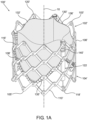
- Figs. 1A and 1B show perspective views of two exemplary types of a prosthetic valve 100, according to some embodiments. It will be appreciated that reference numerals with prime marks (') or double prime marks (") are used throughout Figs. 1A-1B to denote different embodiments of the same elements. Embodiments of the disclosed devices and systems may include any combination of different embodiments of the same elements. Specifically, any reference to an element without single or double prime marks may refer to any alternative embodiment of the same element denoted with a single prime mark or double prime marks.
- the prosthetic valve 100 is deliverable to a patient's target site over a catheter (not shown), and is radially expandable and compressible between a radially compressed, or crimped, configuration, and a radially expanded configuration- shown in Figs. 1A-1B .
- the expanded configuration may include a range of diameters to which the valve 100 may expand, between the compressed configuration and a maximal diameter reached at a fully expanded configuration.
- a plurality of partially expanded configurations may relate to any expansion diameter between radially compressed or crimped configuration, and maximally expanded configuration.
- a prosthetic valve 100 of the current disclosure may include any prosthetic valve configured to be mounted within the native aortic valve, the native mitral valve, the native pulmonary valve, and the native tricuspid valve.
- a prosthetic valve 100 can be delivered to the site of implantation via a delivery assembly carrying the valve 100 in a radially compressed or crimped configuration, toward the target site, to be mounted against the native anatomy, by expanding the valve 100 via various expansion mechanisms.
- Fig. 1A shows an exemplary mechanically expandable valve 100', wherein all reference numerals with prime marks (') shown in Fig. 1A refer to like elements comprised within a mechanically expandable valve.
- Mechanically expandable valves are a category of prosthetic valves that rely on a mechanical actuation mechanism for expansion.
- the mechanical actuation mechanism usually includes a plurality of actuator assemblies, releasably coupled to respective actuation arm assemblies of the delivery apparatus, controlled via a handle of the delivery apparatus for actuating the actuator assemblies to expand the prosthetic valve to a desired diameter.
- Fig. 1B shows an exemplary balloon expandable valve 100", wherein all reference numerals with double prime marks (") shown in Fig. 1B refer to like elements comprised within a balloon expandable valve.
- Balloon expandable valves generally involve a procedure of inflating a balloon within a prosthetic valve, thereby expanding the prosthetic valve 100 within the desired implantation site. Once the valve is sufficiently expanded, the balloon is deflated and retrieved along with the delivery apparatus. While mechanically expandable valves 100' and balloon expandable valves 100" are described and illustrated in conjunction with Figs. 1A-1B , it will be clear that a prosthetic valve 100 may include other expansion mechanisms, such as self-expandable valves. Self-expandable valves include a frame that is shape-set to automatically expand as soon as an outer retaining structure, such as a capsule or a portion of a shaft (not shown), is withdrawn proximally relative to the prosthetic valve.
- a prosthetic valve 100 can comprise an inflow end portion 104 defining an inflow end 105, and an outflow end portion 102 defining an outflow end 103.
- the prosthetic valve 100 can define a valve longitudinal axis 10 extending through the inflow end portion 104 and the outflow end portion 102.
- the outflow end 103 is the proximal end of the prosthetic valve 100
- the inflow end 105 is the distal end of the prosthetic valve 100.
- the outflow end can be the proximal end of the prosthetic valve
- the inflow end can be the distal end of the prosthetic valve.
- proximal generally refers to a position, direction, or portion of any device or a component of a device, which is closer to the user and further away from the implantation site.
- distal generally refers to a position, direction, or portion of any device or a component of a device, which is further away from the user and closer to the implantation site.
- outflow refers to a region of the prosthetic valve through which the blood flows through and out of the valve 100, for example between the valve longitudinal axis 10 and the outflow end 103.
- inflow refers to a region of the prosthetic valve through which the blood flows into the valve 100, for example between inflow end 105 and the valve longitudinal axis 10.
- the valve 100 comprises an annular frame 106 movable between a radially compressed configuration and a radially expanded configuration, and a leaflet assembly 130 mounted within the frame 106.
- the frame 106 can be made of various suitable materials, including plastically-deformable materials such as, but not limited to, stainless steel, a nickel based alloy (e.g., a cobalt-chromium or a nickel-cobalt-chromium alloy such as MP35N alloy), polymers, or combinations thereof.
- the frame 106 When constructed of a plastically-deformable materials, the frame 106, such as frame 106" (and thus the balloon expandable valve 100") can be crimped to a radially compressed configuration on a delivery shaft (not shown), and then expanded inside a patient by an inflatable balloon or equivalent expansion mechanism.
- the frame 106" can be made of shape-memory materials such as, but not limited to, nickel titanium alloy (e.g., Nitinol).
- the frame 106 When constructed of a shape-memory material, the frame 106, such as frame 106' (and thus the mechanically expandable valve 100') can be crimped to a radially compressed configuration and restrained in the compressed configuration by insertion into a shaft or equivalent mechanism of a delivery apparatus (not shown).
- the frame 106 is an annular, stent-like structure comprising a plurality of intersecting struts 110.
- strut encompasses vertical struts, angled struts, attachment posts, commissure windows, and any similar structures described by U.S. Pat. Nos. 7,993,394 and 9,393,110 , which are incorporated herein by reference.
- a strut 110 may be any elongated member or portion of the frame 106.
- the frame 106 can have one or more multiple rows of cells 108 defined by intersecting struts 110.
- the end portions of the struts 110 are forming apices 120 at the outflow end 103 and apices 118 at the inflow end 105.
- the struts 110 can intersect at additional non-apical junctions 116 formed between the outflow apices 120 and the inflow apices 118.
- the non-apical junctions 116 can be equally or unequally spaced apart from each other, and/or from the apices 120, 118, between the outflow end 103 and the inflow end 105.
- the struts 110 are arranged in a lattice-type pattern.
- the struts 110' are positioned diagonally, or offset at an angle relative to, and radially offset from, the valve longitudinal axis 10, when the valve 100' is in an expanded position. It will be clear that the struts 110' can be offset by other angles than those shown in Fig 1B , such as being oriented substantially parallel to the valve longitudinal axis 10.
- the struts 110' are pivotably coupled to each other.
- Frame 106' may comprise openings or apertures at the regions of inflow apices 118', outflow apices 120' and non-apical junctions 116' of the struts 110'.
- Respective hinges can be included at locations where the apertures of struts 110' overlap each other, via fasteners, such as rivets or pins, which extend through the apertures. The hinges can allow the struts 110' to pivot relative to one another as the frame 106' is radially expanded or compressed.
- the struts 110 include a plurality of angled struts and vertical struts.
- the frame 106" comprises a plurality of angled struts 110", and axially extending struts 114.
- the struts are not necessarily coupled to each other via respective hinges, but are otherwise pivotable or bendable relative to each other, so as to permit frame expansion or compression.
- the leaflet assembly 130 comprises a plurality of leaflets 132 (e.g., three leaflets), positioned at least partially within the frame 106, and configured to regulate flow of blood through the prosthetic valve 100 from the inflow end 105 to the outflow end 103. While three leaflets 132 arranged to collapse in a tricuspid arrangement, are shown in the exemplary embodiment illustrated in Figs. 1A-1B , it will be clear that a prosthetic valve 100 can include any other number of leaflets 132.
- the leaflets 132 are made of a flexible material, derived from biological materials (e.g., bovine pericardium or pericardium from other sources), biocompatible synthetic materials, or other suitable materials as known in the art and described, for example, in U.S. Pat. Nos. 6,730,118 , 6,767,362 and 6,908,481 , which are incorporated by reference herein.
- Fig. 2 shows a single representative leaflet 132
- Fig. 3 shows three separated leaflets prior to attachment to the frame 106 and to each other, collectively defining the leaflet assembly 130, according to some embodiments.
- Each leaflet 132 has a rounded cusp end portion 134 defining a cusp edge 135 opposite a free edge 136, and a pair of generally oppositely-directed tabs 138 separating the cusp edge 135 and the free edge 136.
- the cusp edge 135 forms a single scallop.
- the leaflet 132 further comprises an inner surface 152, defined as the surface facing the valve longitudinal axis 10, and an outer surface 154, opposite thereto so as to face the frame 106.
- a mechanically expandable valve 100' comprises a plurality of actuator assemblies 122, configured to facilitate expansion of the valve 100', and in some instances, to lock the valve at an expanded configuration, preventing unintentional recompression thereof.
- Fig. 1A illustrates three actuator assemblies 122, mounted to, and equally spaced, around an inner surface of the frame 106', it should be clear that a different number of actuator assemblies 122 may be utilized, that the actuator assemblies 122 can be mounted to the frame 106' around its outer surface, and that the circumferential spacing between actuator assemblies 122 can be unequal. In some cases, as further illustrated in Fig.
- the actuator assemblies 122 can further serve as commissure posts, to which commissures 140 of the leaflet assembly 130 can be coupled. Details regarding the structure and operation of mechanically expandable valves and delivery system thereof are described in US Patent No. 9,827,093 , U.S. Patent Application Publication Nos. 2019/0060057 , 2018/0153689 and 2018/0344456 , and US Patent Application Nos. 62/870,372 and 62/776,348 , all of which are incorporated herein by reference.
- the upper row of cells comprises a plurality of axially extending window frame portions 112 (which define commissure windows) and a plurality of axially extending struts 114.
- Each axial strut 114 and each window frame portion 112 extends from a junction 116" defined by the convergence of the lower ends of two angled struts 110" to another junction 116" defined by the convergence of the upper ends of two angled struts 110".
- Each commissure window frame portion 112 mounts a respective commissure 140 of the leaflet structure 130.
- Additional frame configurations may include commissure posts attached to the frame, configured to accept commissures 140 extending either through window portions defined therein, or supporting commissure attachment thereto in various other manners.
- some of the cells 108 may be configured to receive commissures 140 attached thereto.
- the uppermost row of cells 108 can be configured to receive tabs 138 of the leaflets 132.
- prosthetic valves including the manner in which commissures may be mounted to their frames, are described in U.S. Patent Nos. 6,730,118 , 7,393,360 , 7,510,575 , 7,993,394 , 8,252,202 , and 9,393,110 ; U.S. Publication Nos.
- the prosthetic valve 100 can further comprise a skirt 123, such as an outer skirt 124 (shown for example in Figs. 15 and 17 ) mounted on the outer surface of the frame 106, configure to function, for example, as a sealing member retained between the frame 106 and the surrounding tissue of the native annulus against which the prosthetic valve 100 is mounted, thereby reducing risk of paravalvular leakage past the prosthetic valve 100.
- a skirt 123 such as an outer skirt 124 (shown for example in Figs. 15 and 17 ) mounted on the outer surface of the frame 106, configure to function, for example, as a sealing member retained between the frame 106 and the surrounding tissue of the native annulus against which the prosthetic valve 100 is mounted, thereby reducing risk of paravalvular leakage past the prosthetic valve 100.
- Such an outer skirt can be made of various suitable biocompatible materials, such as, but not limited to, various synthetic materials (e.g., PET) or natural tissue (e.g. pericardial tissue).
- a primary suture 144 is threaded through the cusp end portion 134 in an in-and-out pattern, also known in the art as a running stitch pattern.
- Fig. 3 shows primary sutures 144 stitched along the cusp end portions 134 of the leaflets 132.
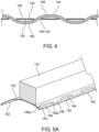
- Fig. 4 shows an enlarged sectional view through a cusp end portion 134 and the primary suture 144 threaded there-through.
- the running stitch extends through penetration points 150 in an in-and-out pattern along the cusp end portion 134, thereby defining a plurality of running stitch portions that include a plurality of inner stitch portions 146 disposed along the leaflet inner surface 152, and a plurality of outer stitch portions 148 disposed along the leaflet outer surface 154, wherein each inner stitch portion 146 and each outer stitch portion 148 is defined between a couple of consecutive penetration points 150.
- the primary suture 144 tracks the curvature of the cusp edge 135, meaning that the primary suture 144 runs along or is generally parallel, with the cusp edge 135.
- a technique for coupling a leaflet 132 along its cusp end portion 134 to at least one section of at least one strut 110 of a frame 106 will now be discussed in accordance with the present teachings.
- the cusp end portion 134 with the primary suture threaded there-through in an in-and-out pattern, is approximated to a strut 110, such that the cusp end portion 134 is preferably positioned radially inward (and optionally in contact with) the inner side of the strut 110.
- a secondary suture 156 is stitched through the primary suture 144 and around at least one section of at least one strut 110, wherein the secondary suture 156 comprises a plurality of self-tightening constructs 158.
- Each self-tightening construct 158 includes at least one loop configured to constrict under tension around the strut 110.
- strut 110 is shown to have a rectangular cross-section in Figs. 5A-5E , it will be clear that this is merely for illustrative purpose, and that the cross-section of a strut 110 can have a rounded, circular, having a polygonal shape, have an irregular shape, or have a shape that changes along the length of the strut.
- the cross-sections of the struts can also remain the same shape, but change size along the length of the strut.
- a self-tightening construct 158 is formed by threading the secondary suture 156 radially outward through the primary suture 144 at penetration point 150a, and forming at least one loop 160 around the strut, such as loop 160a shown in Fig. 5B .
- the self-tightening construct 158 includes more than one loop 160 around the strut 110.
- the secondary suture may be looped again to form a second loop 160b around the strut 110 as shown in Fig. 5C .
- the self-tightening construct 158 can include, in alternative variations, any other number of loops.
- the secondary suture 156 is then passed under the at least one loop 160, such as between both loops 160a, 160b and the strut 110, to form a generally horseshoe-shaped, or u-shaped section 162, which is threaded thereafter through the primary suture 144 in a radially inward direction at penetration point 150b.
- the resulting self-tightening construct 158 is defined between two penetrations points 150 that define at least one outer stitch portion 148 there-between.
- a “radially inward” direction is a direction toward the valve longitudinal axis 10, while a “radially outward” direction is oppositely oriented away from the valve longitudinal axis 10.
- the secondary suture 156 further comprises a plurality of suture pull portions 164 extending over the leaflet inner surface 152, and may be defined between consecutive self-tightening constructs 158.
- a suture pull portion 164 of the secondary suture 156 is defined by extending the secondary suture 156 over the leaflet inner surface 152, for example - in parallel to at least one inner stitch portion 146, and then threading the secondary suture 156 once again through the primary suture 144 in a radially-outward direction, at a consecutive penetration point 150c, at which point another self-tightening construct 158 can be formed in a similar manner.
- Fig. 5E shows a section of a stitch pattern that includes three exemplary self-tightening constructs 158.
- the self-tightening constructs 158 are configured to tighten their grip on the leaflets 132 the more their cusp end portions 134 are pulled radially inward.
- the leaflets 132 collapse radially inward to effectively close the prosthetic valve. This collapse exerts pull forces oriented radially inward in the cusp end portions 134, which tend to pull the suture pull portions 164 radially inward therewith.
- the suture pull portions 164 disposed over the leaflet inner surfaces 152, pull the tails on both sides of each self-tightening construct 158 there-along, which causes the at least one loop 160 to constrict about the strut 110.
- This constriction reduces the diameter of the at least one loop 160, thus forming a mechanical interface between the exterior surfaces of the strut 110 and the interior surfaces of the at least one loop 160.
- This constriction results in static friction between the interior and exterior surfaces at the mechanical interface, causing the at least one loop 160 of each self-tightening construct 158 to tighten in a reduced size or diameter configuration in which tension may be maintained.
- the loops 160 are configured to reduce in diameter when tension is applied to both end portions of the self-tightening construct 158, which increase the grip of the secondary suture 156 around the struts 110, thereby preventing the leaflets 132 from sliding over the struts 110 along the resulting scallop line.
- the primary suture 144 which is threaded in an in-and-out pattern through the cusp end portion 134, may serve as a pledget or cushion between the secondary suture 156 and the leaflet 132.
- the suture pull portion 164 disposed over the leaflet inner surface 152, may be pressed during the repetitive systolic and diastolic cycles against the inner stitch portions 146 of the primary suture 144, which serves as a pledget or cushion so as to prevent direct abrasion that may be otherwise applied to the leaflet 132.
- suture includes, but is not limited to, polymer materials, thread, strand, fiber, wire, other windable materials, organic and inorganic materials, or any other material that is acceptable for medical applications for threading and/or joining together components used in the various embodiments of the valve 100.
- the primary suture 144 can be a multi-filament suture, such as Ethibond Excel ® PET thread (Johnson & Johnson, New Brunswick, N.J.) among other types of suture.
- the secondary suture 156 (as well as secondary suture 170 that will be described further down below) can include ultra-high-molecular-weight polyethylene (UHMwPE), such as a FORCE FIBER ® suture (Teleflex, Wayne, Pa) or DYNEEMA ® fiber (Koninklijke DSM, the Netherlands), among other types of sutures.
- UHMwPE ultra-high-molecular-weight polyethylene
- FORCE FIBER ® suture Teleflex, Wayne, Pa
- DYNEEMA ® fiber Koninklijke DSM, the Netherlands
- the diameter of the secondary suture 156 is sufficiently smaller than that of the primary suture 144, so that threading the secondary suture 156 through the primary suture 144 does not tear or disrupt the primary suture 144.
- a ratio of the diameter of the secondary suture 156 to the diameter of the primary suture 144 is defined as the secondary to primary sutures diameter ratio.
- the secondary to primary sutures diameter ratio is less than 0.8.
- the secondary to primary sutures diameter ratio is less than 0.5.
- the secondary to primary sutures diameter ratio is less than 0.3.
- an inner skirt is attached to an inner surface of the frame, so as to form a more suitable attachment surface for the leaflets.
- the currently disclosed attachment configuration does not require utilization of intermediate fabric strips, since the primary suture 144 serves as a support structure through which the leaflet 132 may be attached to the frame 106, via a secondary suture 156 threaded through the primary suture 144.
- Fabric strips along the inner surface of the frame 106 pose a risk of promoting tissue ingrowth and proliferation after implantation.
- the absence of such fabric or cloth components along the inner side of the frame may significantly reduce such risks, thereby improving the valve's long-term durability and functionality.
- leaflet attachment to the frame of a prosthetic valve along the scalloped edge of the leaflets is devoid of intermediate fabric strips and/or cloth there-between. While tissue ingrowth may still occur along suture materials, such as the primary suture 144, the overall surface area of a suture is significantly smaller than that of traditionally used fabric strips that serve, for example, as inner skirt components.
- the attachment of the leaflets 132 to the struts 110 of the frame 106 is achieved via the secondary suture 156, which is threaded through the primary suture 144 instead of being threaded directly through the leaflet material.
- the primary suture 144 serves as a reinforcement member that resists suture tear-through along the cusp end portions 134, thereby reducing stress concentrations on the leaflets 132 in the vicinity of the scallop line.
- the forces applied to the leaflets 132 during transitioning between the open and closed or coapting states, at the regions of leaflets attachment to the frame are distributed along the length of the primary sutures 144.
- the primary suture 144 serves as a force-distributing element which enhances the durability of the leaflets 132 over time, because the forces are distributed over the primary suture 144 in a substantially equal manner along its length.
- the leaflet 132 can be provided, in some embodiments, with a series of apertures 142 pre-formed along its cusp end portion 134, configured to accept the primary suture 144 and define penetration points 150 through which it may extend in an in-and-out pattern.
- the apertures 142 may serve as the penetration points 150.
- the apertures 142 can be equally spaced from each other in some embodiments.
- the secondary suture 156 is threaded through the primary suture 144 at the penetration points 150, potentially within the apertures 142. According to some embodiments, the secondary suture 156 extends through the primary suture 144 at each penetration point 150. Alternatively, the secondary suture 156 may extend through only some of the penetration points 150, as will be further disclosed herein below.
- the primary suture 144 is threaded through pre-formed apertures 142 along the cusp end portion 134, accuracy of the penetration points 150 for the primary and/or secondary suture 144 and/or 156, respectively, can be pre-set, leading to more accurate placement of the sutures and less errors.
- the apertures 142 are dimensioned to accept the primary suture 144.
- the diameter of the apertures 142 is equal to or smaller than the diameter of the primary suture 144, such that when the primary suture 144 is pass there-through, each aperture 142 tightly retains the primary suture 144 extending there-through.
- the secondary suture 156 extends the boundaries the primary suture 144 at the penetration zones outward, alternative embodiments may include apertures 142 having a diameter that is equal to or smaller than the combined diameters of the primary suture 144 and the secondary suture 156, such that when the secondary suture 156 extends through the primary suture 144 within the aperture 142, the aperture 142 tightly retains them both therein.
- the cusp end portions 134 include markings that may follow the undulating scallop line, such as by tracking the curvature of the cusp edges 135. Such markings, which may be utilized either alternatively to, or in addition to, apertures 142, can further assist the assembler in stitching of the primary suture 144 there-along.
- the secondary suture 156 is threaded through all successive penetration points 150, such that each self-tightening construct 158 is positioned over a single outer stitch portion 148, and each suture pull portion 164 spans over a length of a single inner stitch portion 146.
- the secondary suture 156 is not necessarily threaded through all successive penetration points 150, and may actually skip over one or more penetration point 150, such that a single suture pull portion 164 may span over more than one inner 146 or outer 148 stitch portions.
- Fig. 6 shows an exemplary configuration in which each self-tightening construct 158 is positioned over a single outer stitch portion 148, while the suture pull portion 164 spans over two inner stitch portions 146 and a single outer stitch portion 148 positioned there-between. It will be understood that other configurations are contemplated, wherein either the self-tightening construct 158 and/or the suture pull portion 164 is threaded through non-successive penetration points 150.
- non-successive penetration points refers to any couple of penetration points that include at least one additional penetration point 150 there-between.
- the self-tightening configuration of the secondary suture 156 enables it to be threaded through non-successive penetrations points 150, while retaining a sufficient grip to prevent or at least significantly reduce lateral movement of the cusp end portions 134 over the struts 110.
- the number and position of the self-tightening constructs 158 can be designed and modified in various different manners, based on the desired attachment points, and to facilitate easier attachment by an assembler of the valve 100.
- two primary sutures 144 are inversely threaded in an in-and-out pattern, through the same penetration points 150.
- Fig. 7 shows a sectional view of a cusp end portion 134 which is similar to the view shown in Fig. 4 , except that two primary sutures 144a and 144b are threaded in opposite directions, through the same penetration points 150, such that each couple of successive penetration points 150 define both an inner stitch portion 146 of one of the primary sutures, and an outer stitch portion 148 of the other primary suture.
- Fig. 8 shows a secondary suture 156 threaded through a cusp end portion 134 that includes two primary sutures 144 as shown in Fig. 7 .
- this configuration results in a pattern in which an outer stitch portion 148 and an inner stitch portion 146 extend between each couple of successive penetration points 150, thereby simplifying the assembly procedure by allowing the assembler to thread the secondary suture 156 through any penetration points 150 conveniently available during such a procedure.
- threading sutures through a leaflet 132 involves using a needle or other sharp tool that can pierce through leaflet 132.
- a needle or other sharp tools might lead to unintended cuts, punctures, or other damage to the leaflets 132. Such damage is also difficult to foresee or predict by the manufacturer, and can also be difficult to detect by the end user even when it occurs.
- the primary suture 144 is threaded in an in-and-out manner through penetration points 150, that also serve as the penetration sites through which the secondary suture 156 is threaded.
- penetration points 150 that also serve as the penetration sites through which the secondary suture 156 is threaded.
- the proposed arrangement enables utilization of a secondary suture 156 to attach the leaflet 132 to the struts of the frame, without further puncturing the tissue of the leaflet, thereby improving the leaflets' long-term durability.
- a unique challenge with such double-layered frames 106' is the difficulty to form knots of the sutures at the pivot junctions 116', as relative movement between the intersecting struts 110' can exert scissor-like shearing forces that may compromise the integrity of the sutures in such regions.
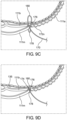
- FIGs. 9A-9D an exemplary technique for coupling leaflets 132 along their cusp end portions 134 to strut sections 111 interconnected at non-apical junctions 116 will now be discussed in accordance with the present teachings.
- the views illustrated in Figs. 9A-9D are taken from a bottom view point of a section of a prosthetic valve, such as a section of prosthetic valve 100".
- a strut section 111 refers to any section of a strut defined between two non-apical junctions 116 of a frame 106.
- each of the sides 190, 191, 192, 193 can be defined by a corresponding planar face of the strut. Nevertheless, as mentioned above, other cross-sectional shapes for the struts are contemplated, such that a side may not necessarily include a planar face.
- the cusp end portion 134 As shown in Figs. 9A-B , the cusp end portion 134, with the primary suture 144 threaded there-through in an in-and-out pattern, is approximated to a strut section 111, such that the cusp end portion 134 is preferably positioned radially inward (and optionally in contact with) the strut inner side 192.
- a secondary suture 170 is stitched through the primary suture 144 and around the strut section 111 in a manner that forms a series of loops or whip stitches 172 spaced from each other along the length of the strut section 111.
- a whip stitch 172 is formed by threading the secondary suture 170 through the primary suture 144 at a penetration point 150, extending the secondary suture 170 around the strut section 111 and back toward the primary suture 144, and then threading secondary suture 170 once again through the primary suture 144 at a consecutive penetration point 150, at which point another whip stitch can be formed in a similar manner.
- whip stitch 172b shown in Fig. 9B is formed by threading the secondary suture 170 radially outward through the primary suture 144 at penetration point 150 (shown in Fig. 9B between loops 172a and 172b), extending it around the strut segment 111 (in the illustrated example, radially outward over the strut proximal side 190, then along the strut outer side 193 which is hidden from view, and radially inward over the strut distal side 195) back (along strut inner side 192) toward the primary suture 144, threading it through the next sequential penetration point 150 to form the next whip stitch 172c in a similar manner.
- the primary suture 144 is positioned proximal or adjacent to the strut proximal side 191.
- An angled whip stitch can be defined as a stitch having at least one portion extending between opposite sides of the strut section 111, oriented at a non-perpendicular angle with respect to a strut section axis defined as tangent to the strut section 111 at the region of the respective stitch.
- the portion extending along the strut distal side 191 between the strut outer side 193 and the strut inner side 192, and the portion extending along the strut inner side 192 (optionally at least partly over the leaflet inner surface 152) between the strut distal side 191 and the strut proximal side 190, are oriented at a non-perpendicular angle relative to a strut section axis which is tangent to the strut 111a at the region of whip stitch 172b.
- each angled whip stitch 172 has a portion extending over one axial side of the strut section 111 wrapped thereby, closer to a junction 116 (at the end of the respective strut section) than the opposite portion extending over the opposite axial side of the strut section.
- the portions of whip stitches 172 extending over the proximal side 190 of strut section 111a are closer to junction 116b than the opposite portions extending over the strut distal side 191.
- an opposite orientation of the whip stitches 172 can include the portions extending over the strut distal side 191 being closer to such a junction 116 than the portions extending over the strut proximal side 190.
- a series of whip stitches 172 wrapped over a single strut section 111 defined between two junction 116 will generally follow the same angled orientation.
- the diameter of the secondary suture 170 is sufficiently smaller than that of the primary suture 144, so that threading the secondary suture 170 through the primary suture 144 does not tear or disrupt the primary suture 144.
- a secondary to primary sutures diameter ratio with respect to secondary sutures 170 can be defined in the same manner described above with respect to secondary sutures 156.
- the secondary to primary sutures diameter ratio is less than 0.8.
- the secondary to primary sutures diameter ratio is less than 0.5.
- the secondary to primary sutures diameter ratio is less than 0.3.
- a series of angled whip stitches 172 (such as stitches 172a, 172b, 172c), up to a final whip stitch 172n defined as the whip stitch which is closest to the non-apical junction 116 on an end of the strut section 111 (junction 116b in Fig. 9B ), wherein the final whip stitch 172n extends up to a final penetration point 150n, after which the secondary suture 170 is utilized to form a junction lock-knot 174 over the corresponding non-apical junction 116.
- a series of angled whip stitches 172 such as stitches 172a, 172b, 172c
- a final whip stitch 172n defined as the whip stitch which is closest to the non-apical junction 116 on an end of the strut section 111 (junction 116b in Fig. 9B )
- the final whip stitch 172n extends up to a final penetration point 150n, after which the secondary suture 170 is utilized to form a junction lock-knot
- a junction lock-knot 174 includes a transition section 176, a first loop 178 and a second loop 180.
- the transition section 176 extends along one axial side of the junction 116, in a direction from the junction first lateral side 198 to the junction second lateral side 199.
- the secondary suture 170 extend over the outer side 193 of strut section 111a from the final penetration point 150n at the strut proximal side 190 to the strut distal side 191, in proximity of the first lateral side 198 of junction 116b.
- the transition section 176 is then formed by extending the secondary suture 170 along the junction distal side 195 in a diagonal direction, such as radially inward from the junction outer side 197 toward the junction inner side 196 and laterally from the junction first lateral side 198 to the junction second lateral side 199.
- the first loop 178 is then formed by extending the secondary suture 170 around a strut section 111 extending from the junction second lateral side 199. Struts sections 111b and 111m are shown to extend from the second lateral side 199 of junction 116b. In the example illustrated in Figs. 9B-C , the first loop 178 is formed by extending the secondary suture 170 from the transition section 176 around strut section 111m.
- the second loop 180 is formed by passing the tail of the secondary suture 170 from the first loop 178, between the transition section 176 and the junction 116, and then looping it back to extend through the first loop 178.
- the secondary suture 170 extending from the first loop 178, is passed, for example in an axial direction (e.g., upward toward outflow end 103), and is then folded over itself backward (e.g., in the distal/downward direction), passing through the first loop 178.
- the tail of the secondary suture is then forcibly pulled to tighten both loops 178, 180 and lock the resulting knot 174.
- the procedure can then be repeated by forming a series of whip stitches 172 attaching the leaflet 132 to the subsequent strut section 111 extending from the junction 116, such as strut section 111b, and forming similar junction lock-knots 174 over all respective junction 116 along the path of the rounded cusp end portions 134.
- this type of stitching pattern facilitates the valve assembly procedure because the knots 174 around the junctions 116 maintain a tight connection between the leaflets and the junctions during assembly.
- the junction lock-knots 174 will maintain tight connection of all whip stitches 172 around the strut section 111 leading to the respective junction 116, relieving the assembler from the need to keep all previous stitches tensioned, and even allowing continuation of the assembly procedure at a later time without the risk of any of the previous loops of knots being loosened.
- the tight connection of the knot 174 keeps all whip stitches 172 along the strut section 111 leading thereto, tightly connected to the strut section 111 as well, thereby reducing relative motion between the suture 170 and strut sections 111 under normal operation of the valve 100 after implantation.
- junction lock-knot 174 also separates between the series of whip stitches 172 around the strut sections 111 extending from both sides of the junction 116.
- the orientation of angled whip stitches 172 formed subsequent to junction lock-knot 174 are not dependent on the configuration of the whip stitches 172 leading to the knot 174, and in fact can have a similar or different angular orientation, as well as similar or different stitching density, and so on. This allows the assembler to switch the angular orientation of angled whip stitched in any desired direction that may be convenient during the assembly procedure, which may differ for different strut portion 111 along the circumference of the valve 100.
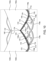
- Fig. 10 shows an example of a portion of a leaflet assembly 130 sutured to the frame 106 (view is from the inside of the valve). As shown, the procedure can be repeated to attach one or more other leaflets 132 to strut sections 111 and junction 116, including formation of similar junction lock-knots 174 around junctions 116 that interconnect two adjacent leaflets 132, such as junction 116d aligned with commissure 140 between leaflets 132a and 132b shown in Fig. 10 .
- the cusp end portion of leaflet 132a is sutured to strut sections 111a, 111b and 111c
- the cusp end portion of leaflet 132b is sutured to strut sections 111d, 111e and 111f.
- the angular orientation of the whip stitches 172 around strut sections 111a, 111b and 111c is generally similar (having their upper/proximal ends closer to junction 116d, for example, than their lower/distal ends).
- the orientation of the whip stitches 172 around strut sections 111d and 116e is reversed to a generally opposite direction, and as shown, after the junction lock-knot 174 around junction 116f, the orientation of the whip stitches 172 around strut section 111f is switched again (to an orientation similar to that of the whip stitches looped over struts section 111a-c).
- the ability to change the orientation of the whip stitches wrapped around each strut segment separately can facilitate the valve assembly process.
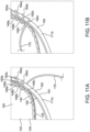
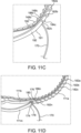
- Figs. 11A-11D show an exemplary technique for coupling leaflets 132 along their cusp end portions 134 to strut sections 111.
- the views illustrated in Figs. 11A-11D are taken from a bottom view point of a section of a prosthetic valve, such as a section of prosthetic valve 100", similar to the view angle of Figs. 9A-9D .
- a primary suture 144 can be threaded through the cusp end portions 134 in an in-and-out pattern, in the same manner described above in conjunction with Fig. 4 , forming a plurality of running stitch portions, including inners stitch portions extending over the leaflet inner surface (hidden from view) and outer stitch portions 148 extending over the leaflet outer surface 154 between penetration points 150, such as outer stitch portions 148a, 148b and 148c shown in Fig. 11A .
- two primary sutures 144a and 144b are threaded in opposite direction through penetration point 150, in a similar manner to that described above in conjunction with Fig. 8 .
- any reference to a primary suture described below in conjunction with Figs. 11A-11D can refer either to a configuration of a single primary suture or to two oppositely threaded sutures, with equal force.
- the cusp end portion 134 As shown in Fig. 11A , the cusp end portion 134, with the primary suture 144 threaded there-through in an in-and-out pattern, is approximated to a strut section 111, such that the cusp end portion 134 is preferably positioned radially inward (and optionally in contact with) the strut inner side 192.
- a secondary suture 170 is looped around the outer stitch portions 148 of the primary suture 144 and around the strut section 111 in a manner that forms a series non-penetrating whip stitches 182 spaced from each other along the length of the strut section 111.
- the secondary suture 170 can be similar to any embodiment described above in conjunction with Figs.
- the secondary suture 170 is then passed beneath the consecutive outer stitch portion 148c, between the outer stitch portion and the leaflet 132 (i.e., between outer stitch portion 148 and leaflet inner surface 152).
- the secondary suture 170 is then folded over outer stitch portion 148c, thereby forming primary-suture-wrapping section 186c.
- the suture can then pass across the strut section 111 (such as across strut outer side 193 toward strut distal side 191 in the example illustrated in Fig. 11C ), repeating these steps to form a following non-penetration whip stitch 182 (such as non-penetration whip stitch 182d).
- Figs. 12A-12D shows another exemplary technique for coupling leaflets 132 along their cusp end portions 134 to strut sections 111 via a series of non-penetrating whip stitches 182, which can be identical to the technique described in conjunction with figs. 11A-11D , except that instead of passing the secondary suture 170 extending from a strut-wrapping section 184 beneath an outer stitch portion 148 and then folding it over the outer stitch portion 148, to form the primary-suture-wrapping section 186 (as shown in Figs. 11B-11C ), the secondary suture 170 is passed over the outer stitch portion 148 (see Fig.
- Fig. 13 shows another stitching configuration which is similar to that shown in Figs. 12A-12D , except that two non-penetration whip stitches 182 pass through each outer stitch portion 148.
- non-penetrating whip stitch 182a' comprises strut-wrapping section 184a' looped around strut section 111, and primary-suture-wrapping section 186a' extending therefrom and looped around outer stitch portion 148a.
- the secondary suture 170 then extends to form strut wrapping section 184a" of non-penetrating whip stitch 182a", and primary-suture-wrapping section 186a' looped around the same outer stitch portion 148a.
- the secondary suture 170 then extends to form subsequent non-penetrating whip stitches 182b' and 182b" in a similar manner, having their primary-suture-wrapping sections 186b' and 186b" looped around outer stitch portion 148b. It is to be understood that while two non-penetration whip stitches 182 passing through a single outer stitch portion 148 are illustrated in Fig. 13 , any other number of non-penetration whip stitches 182 can pass through any single outer stitch portion 148 in a similar manner.
- Fig. 14 shows yet another stitching configuration which is also similar to that shown in Figs. 12A-12D , except that each non-penetrating whip stitch 182 further includes a strut-looping section 185 extending from the respective primary-suture-wrapping section 186, looped solely over the strut section 111.
- non-penetrating whip stitch 182a comprises strut-wrapping section 184a looped around strut section 111, primary-suture-wrapping section 186a extending therefrom and looped around outer stitch portion 148a, and strut-looping section 185a extending from the primary-suture-wrapping section 186a and looped again around the strut section.
- any primary-suture-wrapping section 186 can be looped around any running stitch portion, including around inner stitch portion 146 of the primary suture 144.
- the cusp end portion 134 can be folded over itself such that the cusp edge 135 is rests over the leaflet outer surface 152 facing outward, such that the outer stitch portions 148 are concealed and the inner stitch portions 146 are facing the strut sections 111.
- the non-penetration whip stitches can be formed in the same manner described above, except that the secondary suture is looped around the inner stitch portions 146 instead of around the outer stitch portions.
- attachment of a leaflet 132 along its rounded cusp end portion 134 to one or more strut section 111 can include a combination of one or more single non-penetrating whip stitches 182 passing through corresponding running stitch portions (as illustrated in Figs. 12A-12D ), together with one or more double non-penetrating whip stitches 182 passing through corresponding single running stitch portions (as illustrated in Fig. 13 ), and/or together with one or more single non-penetrating whip stitches 182 looped twice around the strut section 111 (as illustrated in Fig. 14 ).
- Single-pattern or combined-pattern configurations can be implemented along the same strut section 111, or around different strut section of the same valve.
- non-penetrating whip stitches 182, with or without junction lock-knots 174 are described and illustrated above with respect to attachment of leaflets 132 to the frame 106, such attachment configurations can be similarly utilized for attachment of other soft components of the valve 100 to the frame 106, such as skirts 123 that may include any of an inner skirt (not shown) or an outer skirt 124.
- Fig. 15 shows a prosthetic valve 100 with an outer skirt 124, according to some embodiments.
- the prosthetic valve can be similar in all respects to prosthetic valve 100" described in conjunction with Fig. 1B , and in the interest of brevity will not be described further.
- a skirt 123 such as outer skirt 124 shown in Fig. 15 , extends between a skirt proximal end 128 and a skirt distal end 129, and defines a skirt inner surface 125 facing (and is at least partially in contact with) the frame 106, and an opposite skirt outer surface 126 facing away from the frame (toward the native anatomy when implanted in a patient's body).
- the proximal end of the outer skirt follows a zig-zag pattern, corresponding to a zig-zag pattern of strut section 111 to which it may be sutured.
- the skirt distal end 128 is substantially linear (for example, being straight when the skirt is flattened), meaning that it is retained at the same axial level, disposed circumferentially around the inflow end portion 104 of the valve 100.
- a primary suture 144 (one or more) is sutured along portions of the skirt 123 which are aligned with strut sections 111 of the frame 106 in an in-and-out pattern, and a secondary suture 170 (one or more) formed a plurality of non-penetrating whip stitches 182 to couple the skirt 123 to the strut section 111 of the frame 106.
- the primary suture 144 can be stitched through the skirt 123 in an in-and-out pattern according to any of the embodiments disclosed hereinabove, mutatis mutandis.
- any type of non-penetrating whip stitches 182 disclosed above with respect to attachment of leaflets 132 to struts 111 can be similarly adapted to attach the skirt 123 to struts 111 in the same manner, mutatis mutandis.
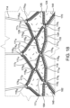
- Fig. 16 shows a partial view or the outer skirt 124 coupled to struts 111 of the frame 106 of the valve 100 shown in Fig. 15 , from a valve-internal view angle.
- the leaflet assembly 130 is omitted from view in Fig. 16 for simplicity.
- a primary suture 144 is stitched in an in-and-out pattern along the skirt proximal end 129, for example tracking its zig-zagged shape.
- the primary suture 144 can define a series of running stitch portions that include inner stitch portion 146, disposed over skirt inner surface 125, and outer skirt portion 148, disposed over skirt outer surface 126.
- a plurality of non-penetrating whip stitches 182 are then looped around strut sections 111 via strut-wrapping sections 184, and around running stitch portion of the primary suture 144, such as over and between inner stitch portions 146 and the skirt inner surface 125.
- non-penetrating whip stitches 182 similar to those described in conjunction with Figs. 12A-D , is illustrated in Fig. 16 , for example along strut sections 111m, 111n, 111o, and 111p, it is to be understood that the skirt can be sutured to the corresponding strut section 111 by implementing any of the suturing patterns and methods described above in conjunction with Figs. 11A-14 , mutatis mutandis.
- junction lock-knots 174 are similarly used to attach the skirt 123, such as outer skirt 124, to junctions 116 disposed between strut section 111 to which the skirt is sutured via non-penetrating whip stitches 182, such as junction lock-knots 174m, 174n, 174o, 174p and 174q formed over respective junctions 116m, 116n, 116o, 116p and 116q in the illustrated example.
- the configuration and methods of forming such junction lock-knots 174 is similar to that described hereinabove with respect to attachment of leaflets 132 to junction 116, mutatis mutandis.
- the skirt 123 is coupled to additional junctions 116, which are not necessarily disposed between strut section 111 around which non-penetrating whip stitches 182 extend, via additional knots, which are not necessarily the junction lock-knots 172 but may be implemented as other knots known in the art, as schematically shown in Fig. 16 for knots 166r, 166s and 166t around respective junctions 116r, 116s and 116t, for example.
- Fig. 17 shows another valve 100 comprising an outer skirt 124 that can be similar to the valve and skirt of Fig. 15 , except that the skirt distal end 128 is not linear but rather tracks the shape of the strut sections 111 along the inflow end portion 104 of the valve, which can be undulated or arc-shaped as illustrated in Fig. 17 , or can otherwise be zig-zagged or otherwise shaped to follow other paths defines by distal strut sections of the valve.
- Fig. 18 shows a partial view or the outer skirt 124 coupled to struts 111 of the frame 106 of the valve 100 shown in Fig. 17 , from valve-bottom-internal view angle.
- the leaflet assembly 130 is omitted from view in Fig. 18 for simplicity.
- a primary suture 144 is stitched in an in-and-out pattern along the skirt distal end 129, for example tracking its undulating shape. This can be in addition to the primary suture 144 stitched along the skirt proximal end 129, implemented in the same manner described above.
- a plurality of non-penetrating whip stitches 182 are then looped around the strut sections 111 (of the inflow end portion 104) by a series of strut-wrapping sections 184, and around running stitch portion of the primary suture 144, such as over and between inner stitch portions 146 and the skirt inner surface 125. While a specific embodiment of non-penetrating whip stitches 182, similar to those described in conjunction with Figs. 12A-D , is illustrated in Fig. 18 , for example along strut sections 111u and 111w, it is to be understood that the skirt can be sutured to the corresponding strut section 111 by implementing any of the suturing patterns and methods described above in conjunction with Figs. 11A-14 , mutatis mutandis.
- junction lock-knots 174 are similarly used to attach the outer skirt 124 to junctions 116 along the inflow end portion 104, such as junction lock-knots 174r, 174s and 174t formed around respective junctions 116r, 116s and 116t in the illustrated example, following the same configuration and methods described hereinabove with respect to attachment of leaflets 132 to junction 116, mutatis mutandis.
- the skirt 123 is attached to additional strut sections 111 disposed between the skirt proximal end 129 and skirt distal end 128 via non-penetrating whip stitches 182 in the same manner and according to all optional embodiments described above.
- primary suture 144 one or more
- a series of non-penetrating whip stitches 182, implemented according to any of the embodiments described above with respect to Figs. 11A-14 can be utilized to attached the skirt to the corresponding strut section 111, as shown for example in Fig. 18 along strut sections 111r, 111s, 111t and 111v.
- the skirt 123 such as outer skirt 124, is attached to additional junctions 116 disposed between the skirt proximal end 129 and skirt distal end 128 via junction lock-knots 174 in the same manner and according to all optional embodiments described above.
- Some valve are provided with an inner skirt (not shown) disposed around the inner surface of the frame. While outer skirts 124 are illustrated for demonstrating various attachment configurations thereof to the frames throughout Figs. 15-18 , it is to be understood that the same embodiments described above with respect to outer skirt attachment, may be implemented in a similar manner for attachment of inner skirts to the frame, mutatis mutandis.
- junction lock-knots 174 can be utilized for attachment of a skirt 123 (including any of an inner skirt or an outer skirt) to junctions 116 along any of the skirt proximal end 129, skirt distal end 128, and/or to junctions 116 disposed between the skirt proximal end 129 and skirt distal end 128 (when the skirt is attached to the frame), without the use of non-penetrating whip stitches 182 around strut sections 111.
- a skirt can be sutured to corresponding strut sections 111 along any of the skirt proximal end 129, skirt distal end 128, and/or to strut sections 111 disposed between the skirt proximal end 129 and skirt distal end 128 (when the skirt is attached to the frame) via a series of whip stitches 172 that can penetrate through the primary suture 144, with junction lock-knots 174 formed around junction 116 disposed between such strut sections 111, in the same manner and following similar methods described above in Figs. 10A-11 for attachment of leaflets 132 to the frame 106, mutatis mutandis.
- this application discloses the additional examples enumerated below. It should be noted that one feature of an example in isolation or more than one feature of the example taken in combination and, optionally, in combination with one or more features of one or more further examples are further examples also falling within the disclosure of this application.
- Example 1 A prosthetic valve comprising:
- Example 2 The prosthetic valve of any example herein, particularly example 1, wherein the at least one loop of each self-tightening construct comprises two loops.
- Example 3 The prosthetic valve of any example herein, particularly any one of examples 1 or 2, wherein each self-tightening construct further comprises a u-shaped section partially extending between the at least one loop and the strut.
- Example 4 The prosthetic valve of any example herein, particularly any one of examples 1 to 3, wherein the leaflet comprises a leaflet inner surface and a leaflet outer surface, and wherein the primary suture comprises a plurality of inner stitch portions disposed along the leaflet inner surface, and plurality of outer stitch portions disposed along the leaflet outer surface, each inner stitch portion and each outer stitch portion defined between respective penetration points.
- Example 5 The prosthetic valve of any example herein, particularly example 4, wherein the self-tightening construct is defined between two penetrations points that define at least one outer stitch portion there-between.
- Example 6 The prosthetic valve of any example herein, particularly any one of examples 4 or 5, wherein the secondary suture further comprises a plurality of suture pull portions extending over the leaflet inner surface.
- Example 10 The prosthetic valve of any example herein, particularly example 9, wherein a secondary to primary sutures diameter ratio is equal to or smaller than 0.8.
- Example 11 The prosthetic valve of any example herein, particularly example 9, wherein a secondary to primary sutures diameter ratio is equal to or smaller than 0.5.
- Example 12 The prosthetic valve of any example herein, particularly example 9, wherein a secondary to primary sutures diameter ratio is equal to or smaller than 0.3.
- Example 13 The prosthetic valve of any example herein, particularly any one of examples 1 to 12, wherein the cusp end portion of each leaflet comprises a series of pre-formed apertures.
- Example 14 The prosthetic valve of any example herein, particularly example 13, wherein the apertures are dimensioned to accept the at least one primary suture, thereby serving as the penetration points.
- Example 15 The prosthetic valve of any example herein, particularly any one of examples 13 or 14, wherein the apertures are equally spaced from each other.
- Example 16 The prosthetic valve of any example herein, particularly any one of examples 13 to 15, wherein the diameter of the apertures is equal to or smaller than the diameter of the primary suture.
- Example 17 The prosthetic valve of any example herein, particularly any one of examples 13 to 15, wherein the diameter of the apertures is equal to or smaller than the combined diameters of the primary suture and the secondary suture.
- Example 18 The prosthetic valve of any example herein, particularly any one of examples 1 to 17, wherein the secondary suture is threaded through all successive penetration points.
- Example 19 The prosthetic valve of any example herein, particularly any one of examples 1 to 18, wherein the at least one primary suture comprises two primary sutures, which are inversely threaded in an in-and-out pattern, through the same penetration points.
- Example 20 The prosthetic valve of any example herein, particularly any one of examples 13 to 15, wherein the diameter of the apertures is equal to or smaller than the diameter of the two primary sutures.
- Example 22 The prosthetic valve of any example herein, particularly any one of examples 1 to 21, wherein the at least one primary suture tracks the curvature of the at least one cusp edge.
- Example 24 The prosthetic valve of any example herein, particularly any one of examples 1 to 23, wherein the secondary suture comprises an ultra-high-molecular-weight polyethylene.
- Example 25 The prosthetic valve of any example herein, particularly any one of examples 1 to 24, wherein the prosthetic valve is devoid of fabric strips and/or cloth between the cusp end portions of the leaflets and the struts they are attached to.
- Example 26 A method of assembling a prosthetic valve, the method comprising steps of:
- Example 27 The method of any example herein, particularly example 26, wherein the step of stitching a secondary suture includes threading the secondary suture radially outward through the primary suture at a penetration point, thereby forming the at least one loop around the at least one strut.
- Example 28 The method of any example herein, particularly example 27, wherein the step of stitching a secondary suture comprises looping the secondary suture again around the at least one strut after forming a first loop, thereby forming two loops for each self-tightening construct.
- Example 30 The prosthetic valve of any example herein, particularly any one of examples 26 to 29, further comprising a step of extending the secondary suture over a leaflet inner surface, and then threading the secondary suture once again through the primary suture in a radially-outward direction, thereby forming at least one suture pull portion extending over the leaflet inner surface.
- Example 31 The prosthetic valve of any example herein, particularly any one of examples 26 to 30, wherein the cusp end portion of each leaflet comprises a series of pre-formed apertures, and wherein the step of threading a primary suture comprises threading the primary suture in an in-and-out pattern through the series of pre-formed apertures.
- Example 32 A prosthetic valve comprising:
- Example 33 The prosthetic valve of any example herein, particularly example 32, wherein each junction lock-knot comprises:
- Example 34 The prosthetic valve of any example herein, particularly example 33, wherein the transition section extends in a diagonal direction from one radial side of the junction toward the opposite radial side of the junction, as well as from one lateral side of the junction to the opposite lateral side of the junction.
- Example 35 The prosthetic valve of any example herein, particularly any one of examples 33 or 34, wherein both the first loop and the second loop are tightly tensioned around the junction.
- Example 36 The prosthetic valve of any example herein, particularly any one of examples 32 to 35, wherein each plurality of whip stitches wrapped around a single strut section are angled whip stitches, oriented in the same direction along the length of the corresponding strut section.
- Example 37 The prosthetic valve of any example herein, particularly example 36, wherein the cusp end portion is sutured to at least two strut sections extending from both lateral sides of a selected junction, via a plurality of whip stitches wrapped around each of the respective strut sections and a junction lock-knot around the junction positioned there-between, and wherein the plurality of whip stitches around one of the strut sections are angled in a direction opposite to that of the plurality of the whip stitches wrapped around the other strut section.
- Example 39 The prosthetic valve of any example herein, particularly example 38, wherein a secondary to primary sutures diameter ratio is equal to or smaller than 0.8.
- Example 40 The prosthetic valve of any example herein, particularly example 38, wherein a secondary to primary sutures diameter ratio is equal to or smaller than 0.5.
- Example 41 The prosthetic valve of any example herein, particularly example 38, wherein a secondary to primary sutures diameter ratio is equal to or smaller than 0.3.
- Example 42 The prosthetic valve of any example herein, particularly any one of examples 32 to 41, wherein the cusp end portion of each leaflet comprises a series of pre-formed apertures.
- Example 43 The prosthetic valve of any example herein, particularly example 42, wherein the apertures are dimensioned to accept the at least one primary suture, thereby serving as the penetration points.
- Example 44 The prosthetic valve of any example herein, particularly any one of examples 42 or 43, wherein the apertures are equally spaced from each other.
- Example 45 The prosthetic valve of any example herein, particularly any one of examples 42 to 44, wherein the diameter of the apertures is equal to or smaller than the diameter of the primary suture.
- Example 46 The prosthetic valve of any example herein, particularly any one of examples 42 to 44, wherein the diameter of the apertures is equal to or smaller than the combined diameters of the primary suture and the secondary suture.
- Example 47 The prosthetic valve of any example herein, particularly any one of examples 32 to 46, wherein the at least one primary suture comprises two primary sutures, which are inversely threaded in an in-and-out pattern, through the same penetration points.
- Example 48 The prosthetic valve of any example herein, particularly any one of examples 42 to 44, wherein the diameter of the apertures is equal to or smaller than the diameter of the two primary sutures.
- Example 49 The prosthetic valve of any example herein, particularly example 48, wherein the diameter of the apertures is equal to or smaller than the combined diameters of the two primary sutures and the secondary suture.
- Example 50 The prosthetic valve of any example herein, particularly any one of examples 32 to 49, wherein the at least one primary suture tracks the curvature of the at least one cusp edge.
- Example 51 The prosthetic valve of any example herein, particularly any one of examples 32 to 50, wherein the primary suture comprises a multi-filament suture.
- Example 52 The prosthetic valve of any example herein, particularly any one of examples 32 to 51, wherein the secondary suture comprises an ultra-high-molecular-weight polyethylene.
- Example 53 The prosthetic valve of any example herein, particularly any one of examples 32 to 52, wherein the prosthetic valve is devoid of fabric strips and/or cloth between the cusp end portions of the leaflets and the strut sections and junctions they are attached to.
- Example 54 A method of assembling a prosthetic valve, the method comprising steps of:
- Example 55 The method of any example herein, particularly example 54, wherein the step of forming a junction lock-knot comprises extending the secondary suture from the final whip stitch disposed at a first lateral side of the junction, over one axial side of the junction, in a direction toward a second lateral side of the junction, thereby forming a transition section of the junction lock-knot.
- Example 56 The method of any example herein, particularly example 55, wherein the step of forming a junction lock-knot further comprises extending the secondary suture from the transition section around a strut section extending from the second lateral side of the junction, thereby forming a first loop of the junction lock-knot.
- Example 57 The method of any example herein, particularly example 56, wherein the step of forming a junction lock-knot further comprises extending the secondary suture from the first loop, between the transition section and the junction, folding the secondary suture back over itself and passing it through the first loop, thereby forming a second loop of the junction lock-knot.
- Example 58 The method of any example herein, particularly example 57, wherein the step of forming a junction lock-knot further comprises forcibly pulling the tail of the second loop to tighten both the first loop and the second loop around the junction.
- Example 59 The method of any example herein, particularly any one of examples 55 to 58, wherein forming the transition section comprises extending the secondary suture in a diagonal direction from one radial side of the junction toward an opposite radial side of the junction, as well as from one lateral side of the junction to the opposite lateral side of the junction.
- Example 61 The method of any example herein, particularly example 60, wherein stitching the secondary suture around the at least one strut section comprises stitching around at least two strut sections separated from each other by a mutual junction, such that all whip stitches around one of the strut sections are formed as angled whip stitches oriented in one direction, while all whip stitches around the other strut section are formed as angled whip stitched oriented in a second direction, opposite to the first direction.
- Example 94 The prosthetic valve of any example herein, particularly any one of examples 91 to 93, wherein each junction lock-knot comprises:
- Example 96 The prosthetic valve of any example herein, particularly any one of examples 94 or 95, wherein both the first loop and the second loop are tightly tensioned around the junction.
- Example 97 The prosthetic valve of any example herein, particularly any one of examples 91 to 96, wherein each plurality of whip stitches wrapped around a single strut section are angled whip stitches, oriented in the same direction along the length of the corresponding strut section.
- Example 98 The prosthetic valve of any example herein, particularly example 97, wherein the skirt proximal end is sutured to at least two strut sections extending from both lateral sides of a selected junction, via a plurality of whip stitches wrapped around each of the respective strut sections and a junction lock-knot around the junction positioned there-between, and wherein the plurality of whip stitches around one of the strut sections are angled in a direction opposite to that of the plurality of the whip stitches wrapped around the other strut section.
- Example 99 The prosthetic valve of any example herein, particularly any one of examples 91 to 98, wherein the skirt distal end is coupled to at least one strut section at an inflow end portion of the valve via at least one additional primary suture threaded at penetration points therethrough in an in-and-out pattern, and an additional secondary suture threaded through the primary suture and wrapped around the strut section at the inflow end portion in a series of whip stitches spaced from each other along the length of the strut section, and wherein the skirt distal end is further coupled to at least one junction at an end of the strut section at the inflow end portion via an additional junction lock-knot.
- Example 102 The prosthetic valve of any example herein, particularly example 101, wherein a secondary to primary sutures diameter ratio is equal to or smaller than 0.8.
- Example 103 The prosthetic valve of any example herein, particularly example 101, wherein a secondary to primary sutures diameter ratio is equal to or smaller than 0.5.
- Example 105 The prosthetic valve of any example herein, particularly any one of examples 91 to 104, wherein the skirt proximal end comprises a series of pre-formed apertures.
- Example 106 The prosthetic valve of any example herein, particularly example 105, wherein the apertures are dimensioned to accept the at least one primary suture, thereby serving as the penetration points.
- Example 107 The prosthetic valve of any example herein, particularly any one of examples 105 or 106, wherein the apertures are equally spaced from each other.
- Example 108 The prosthetic valve of any example herein, particularly any one of examples 105 to 107, wherein the diameter of the apertures is equal to or smaller than the diameter of the primary suture.
- Example 109 The prosthetic valve of any example herein, particularly any one of examples 105 to 107, wherein the diameter of the apertures is equal to or smaller than the combined diameters of the primary suture and the secondary suture.
- Example 110 The prosthetic valve of any example herein, particularly any one of examples 91 to 109, wherein the at least one primary suture comprises two primary sutures, which are inversely threaded in an in-and-out pattern, through the same penetration points.
- Example 111 The prosthetic valve of any example herein, particularly any one of examples 105 to 107, wherein the diameter of the apertures is equal to or smaller than the diameter of the two primary sutures.
- Example 113 The prosthetic valve of any example herein, particularly any one of examples 91 to 112, wherein the primary suture comprises a multi-filament suture.
- Example 114 The prosthetic valve of any example herein, particularly any one of examples 91 to 113, wherein the secondary suture comprises an ultra-high-molecular-weight polyethylene.
- Example 115 The prosthetic valve of any example herein, particularly any one of examples 91 to 114, wherein the skirt is an outer skirt, disposed around an outer surface of the frame.
- Example 116 A method of assembling a prosthetic valve, the method comprising steps of:
- Example 117 The method of any example herein, particularly example 116, wherein the step of forming a junction lock-knot comprises extending the secondary suture from the final whip stitch disposed at a first lateral side of the junction, over one axial side of the junction, in a direction toward a second lateral side of the junction, thereby forming a transition section of the junction lock-knot.
- Example 118 The method of any example herein, particularly example 117, wherein the step of forming a junction lock-knot further comprises extending the secondary suture from the transition section around a strut section extending from the second lateral side of the junction, thereby forming a first loop of the junction lock-knot.
- Example 120 The method of any example herein, particularly example 119, wherein the step of forming a junction lock-knot further comprises forcibly pulling the tail of the second loop to tighten both the first loop and the second loop around the junction.
- Example 122 The method of any example herein, particularly any one of examples 116 to 121, wherein forming the plurality of whip stitches around any single strut section comprises forming a plurality of angled whip stitches oriented in the same direction around the length of the corresponding strut section.
- Example 124 The method of any example herein, particularly any one of examples 116 to 123, wherein the skirt proximal end comprises a series of pre-formed apertures, and wherein the step of threading a primary suture comprises threading the primary suture in an in-and-out pattern through the series of pre-formed apertures.
- Example 125 The method of any example herein, particularly any one of examples 116 to 124, wherein the skirt is an outer skirt, disposed around an outer surface of the frame.
- Example 127 The prosthetic valve of any example herein, particularly example 126, wherein the skirt proximal end follows a zig-zag pattern.
- Example 128 The prosthetic valve of any example herein, particularly example 127, wherein the at least one primary suture tracks the zig-zag pattern of the skirt proximal end.
- Example 129 The prosthetic valve of any example herein, particularly any one of examples 126 to 128, wherein the primary suture defines a series of running stitch portions, and wherein each primary-suture-wrapping section is looped around a corresponding running stitch portion and extends between the running stitch portion and the skirt proximal end.
- Example 130 The prosthetic valve of any example herein, particularly any one of examples 126 to 129, wherein the secondary suture does not penetrate through the skirt.
- Example 131 The prosthetic valve of any example herein, particularly any one of examples 126 to 130, wherein the secondary suture does not penetrate through the primary suture.
- Example 132 The prosthetic valve of any example herein, particularly any one of examples 126 to 131, wherein each junction is defined between: two opposite axial sides comprising a junction proximal side and a junction distal side; two opposite radial sides comprising a junction inner side and a junction outer side; and two opposite lateral sides comprising a junction first lateral side and a junction second lateral side; wherein the skirt proximal end is further coupled to at least one junction at an end of the strut section via a junction lock-knot formed by the second suture, and wherein the junction lock-knot is configured to maintain tension on the plurality of the non-penetrating whip stitches wrapped around the corresponding strut section leading to the junction first lateral section.
- Example 133 The prosthetic valve of any example herein, particularly example 132, wherein each junction lock-knot comprises:
- Example 134 The prosthetic valve of any example herein, particularly example 133, wherein the transition section extends in a diagonal direction from one radial side of the junction toward the opposite radial side of the junction, as well as from one lateral side of the junction to the opposite lateral side of the junction.
- Example 135. The prosthetic valve of any example herein, particularly any one of examples 133 or 134, wherein both the first loop and the second loop are tightly tensioned around the junction.
- Example 136 The prosthetic valve of any example herein, particularly any one of examples 132 to 135, wherein each plurality of non-penetrating whip stitches wrapped around a single strut section are angled non-penetrating whip stitches, oriented in the same direction along the length of the corresponding strut section.
- Example 147 The method of any example herein, particularly any one of examples 145 or 146, wherein the skirt is an outer skirt and the running stitch portion is an inner stitch portion of the primary suture.
- Example 148 The method of any example herein, particularly any one of examples 143 to 147, further comprising a step of forming a junction lock-knot extending from the final non-penetrating whip stitch around a junction at a respective end of the corresponding strut section, wherein the junction lock-knot is configured to maintain tension on the plurality of non-penetrating whip stitches wrapped around the strut section leading to the junction first lateral section.
- Example 150 The method of any example herein, particularly example 149, wherein the step of forming a junction lock-knot further comprises extending the secondary suture from the transition section around a strut section extending from the second lateral side of the junction, thereby forming a first loop of the junction lock-knot.
- Example 151 The method of any example herein, particularly example 150, wherein the step of forming a junction lock-knot further comprises extending the secondary suture from the first loop, between the transition section and the junction, folding the secondary suture back over itself and passing it through the first loop, thereby forming a second loop of the junction lock-knot.
- Example 153 The method of any example herein, particularly any one of examples 149 to 152, wherein forming the transition section comprises extending the secondary suture in a diagonal direction from one radial side of the junction toward an opposite radial side of the junction, as well as from one lateral side of the junction to the opposite lateral side of the junction.
- Example 154 The method of any example herein, particularly any one of examples 148 to 153, wherein forming the plurality of whip stitches around any single strut section comprises forming a plurality of angled whip stitches oriented in the same direction around the length of the corresponding strut section.
- Example 155 The method of any example herein, particularly example 154, wherein forming the plurality of whip stitches around the at least one strut section comprises forming a plurality of whip stitches around at least two strut sections separated from each other by a mutual junction, such that all whip stitches around one of the strut sections are formed as angled whip stitches oriented in one direction, while all whip stitches around the other strut section are formed as angled whip stitched oriented in a second direction, opposite to the first direction.
Landscapes
- Health & Medical Sciences (AREA)
- Cardiology (AREA)
- Engineering & Computer Science (AREA)
- Biomedical Technology (AREA)
- Heart & Thoracic Surgery (AREA)
- Transplantation (AREA)
- Oral & Maxillofacial Surgery (AREA)
- Vascular Medicine (AREA)
- Life Sciences & Earth Sciences (AREA)
- Animal Behavior & Ethology (AREA)
- General Health & Medical Sciences (AREA)
- Public Health (AREA)
- Veterinary Medicine (AREA)
- Mechanical Engineering (AREA)
- Prostheses (AREA)
Applications Claiming Priority (4)
| Application Number | Priority Date | Filing Date | Title |
|---|---|---|---|
| US202063050657P | 2020-07-10 | 2020-07-10 | |
| US202163211417P | 2021-06-16 | 2021-06-16 | |
| EP21748770.1A EP4178488B1 (fr) | 2020-07-10 | 2021-07-09 | Configurations de fixation de feuillets valvulaires et de jupes aux armatures de valvules prothétiques |
| PCT/US2021/041002 WO2022011209A1 (fr) | 2020-07-10 | 2021-07-09 | Configurations de fixation de feuillets valvulaires et de jupes aux armatures de valvules prothétiques |
Related Parent Applications (1)
| Application Number | Title | Priority Date | Filing Date |
|---|---|---|---|
| EP21748770.1A Division EP4178488B1 (fr) | 2020-07-10 | 2021-07-09 | Configurations de fixation de feuillets valvulaires et de jupes aux armatures de valvules prothétiques |
Publications (2)
| Publication Number | Publication Date |
|---|---|
| EP4582061A2 true EP4582061A2 (fr) | 2025-07-09 |
| EP4582061A3 EP4582061A3 (fr) | 2025-10-08 |
Family
ID=77127122
Family Applications (2)
| Application Number | Title | Priority Date | Filing Date |
|---|---|---|---|
| EP21748770.1A Active EP4178488B1 (fr) | 2020-07-10 | 2021-07-09 | Configurations de fixation de feuillets valvulaires et de jupes aux armatures de valvules prothétiques |
| EP25177652.2A Pending EP4582061A3 (fr) | 2020-07-10 | 2021-07-09 | Configurations de fixation de feuillet et de jupe aux cadres de valvules prothétiques |
Family Applications Before (1)
| Application Number | Title | Priority Date | Filing Date |
|---|---|---|---|
| EP21748770.1A Active EP4178488B1 (fr) | 2020-07-10 | 2021-07-09 | Configurations de fixation de feuillets valvulaires et de jupes aux armatures de valvules prothétiques |
Country Status (6)
| Country | Link |
|---|---|
| US (2) | US12502275B2 (fr) |
| EP (2) | EP4178488B1 (fr) |
| JP (2) | JP7801302B2 (fr) |
| CN (3) | CN216570344U (fr) |
| ES (1) | ES3041700T3 (fr) |
| WO (1) | WO2022011209A1 (fr) |
Families Citing this family (5)
| Publication number | Priority date | Publication date | Assignee | Title |
|---|---|---|---|---|
| CN216570344U (zh) * | 2020-07-10 | 2022-05-24 | 爱德华兹生命科学公司 | 假体瓣膜 |
| US12383395B2 (en) * | 2020-12-22 | 2025-08-12 | Medtronic, Inc. | Skirt-reinforcement members for prosthetic valve devices |
| CA3265500A1 (fr) * | 2022-08-31 | 2024-03-07 | Edwards Lifesciences Corporation | Ensembles et procédés de fixation de composants de prothèse valvulaire à une structure d'une prothèse valvulaire cardiaque |
| CN117481870A (zh) * | 2023-12-01 | 2024-02-02 | 江苏臻亿医疗科技有限公司 | 瓣膜支架及人工瓣膜 |
| WO2026006535A1 (fr) * | 2024-06-27 | 2026-01-02 | Edwards Lifesciences Corporation | Prothèse valvulaire cardiaque |
Citations (11)
| Publication number | Priority date | Publication date | Assignee | Title |
|---|---|---|---|---|
| US6730118B2 (en) | 2001-10-11 | 2004-05-04 | Percutaneous Valve Technologies, Inc. | Implantable prosthetic valve |
| US7993394B2 (en) | 2008-06-06 | 2011-08-09 | Ilia Hariton | Low profile transcatheter heart valve |
| US8252202B2 (en) | 2007-05-17 | 2012-08-28 | Dic Corporation | Nematic liquid crystal composition and bistable nematic liquid crystal display |
| US9155619B2 (en) | 2011-02-25 | 2015-10-13 | Edwards Lifesciences Corporation | Prosthetic heart valve delivery apparatus |
| US9393110B2 (en) | 2010-10-05 | 2016-07-19 | Edwards Lifesciences Corporation | Prosthetic heart valve |
| US9827093B2 (en) | 2011-10-21 | 2017-11-28 | Edwards Lifesciences Cardiaq Llc | Actively controllable stent, stent graft, heart valve and method of controlling same |
| US20180153689A1 (en) | 2016-12-06 | 2018-06-07 | Edwards Lifesciences Corporation | Mechanically expanding heart valve and delivery apparatus therefor |
| US20180325665A1 (en) | 2017-05-15 | 2018-11-15 | Edwards Lifesciences Corporation | Devices and methods of commissure formation for prosthetic heart valve |
| US20180344456A1 (en) | 2017-06-05 | 2018-12-06 | Edwards Lifesciences Corporation | Mechanically expandable heart valve |
| US20190060057A1 (en) | 2017-08-22 | 2019-02-28 | Edwards Lifesciences Corporation | Gear drive mechanism for heart valve delivery apparatus |
| US20190105153A1 (en) | 2017-06-05 | 2019-04-11 | Edwards Lifesciences Corporation | Mechanically expandable heart valve |
Family Cites Families (308)
| Publication number | Priority date | Publication date | Assignee | Title |
|---|---|---|---|---|
| GB1127325A (en) | 1965-08-23 | 1968-09-18 | Henry Berry | Improved instrument for inserting artificial heart valves |
| US3587115A (en) | 1966-05-04 | 1971-06-28 | Donald P Shiley | Prosthetic sutureless heart valves and implant tools therefor |
| US3548417A (en) | 1967-09-05 | 1970-12-22 | Ronnie G Kischer | Heart valve having a flexible wall which rotates between open and closed positions |
| USRE30912E (en) | 1968-09-16 | 1982-04-27 | Hancock Laboratories, Inc. | Stent for heart valve |
| US3671979A (en) | 1969-09-23 | 1972-06-27 | Univ Utah | Catheter mounted artificial heart valve for implanting in close proximity to a defective natural heart valve |
| US3657744A (en) | 1970-05-08 | 1972-04-25 | Univ Minnesota | Method for fixing prosthetic implants in a living body |
| US3714671A (en) | 1970-11-30 | 1973-02-06 | Cutter Lab | Tissue-type heart valve with a graft support ring or stent |
| US3755823A (en) | 1971-04-23 | 1973-09-04 | Hancock Laboratories Inc | Flexible stent for heart valve |
| GB1402255A (en) | 1971-09-24 | 1975-08-06 | Smiths Industries Ltd | Medical or surgical devices of the kind having an inflatable balloon |
| US4035849A (en) | 1975-11-17 | 1977-07-19 | William W. Angell | Heart valve stent and process for preparing a stented heart valve prosthesis |
| CA1069652A (fr) | 1976-01-09 | 1980-01-15 | Alain F. Carpentier | Valvule prosthetique avec anneau deformable |
| US4056854A (en) | 1976-09-28 | 1977-11-08 | The United States Of America As Represented By The Department Of Health, Education And Welfare | Aortic heart valve catheter |
| US4297749A (en) | 1977-04-25 | 1981-11-03 | Albany International Corp. | Heart valve prosthesis |
| US4265694A (en) | 1978-12-14 | 1981-05-05 | The United States Of America As Represented By The Department Of Health, Education And Welfare | Method of making unitized three leaflet heart valve |
| US4222126A (en) | 1978-12-14 | 1980-09-16 | The United States Of America As Represented By The Secretary Of The Department Of Health, Education & Welfare | Unitized three leaflet heart valve |
| US4574803A (en) | 1979-01-19 | 1986-03-11 | Karl Storz | Tissue cutter |
| GB2056023B (en) | 1979-08-06 | 1983-08-10 | Ross D N Bodnar E | Stent for a cardiac valve |
| US4373216A (en) | 1980-10-27 | 1983-02-15 | Hemex, Inc. | Heart valves having edge-guided occluders |
| US4388735A (en) | 1980-11-03 | 1983-06-21 | Shiley Inc. | Low profile prosthetic xenograft heart valve |
| US4339831A (en) | 1981-03-27 | 1982-07-20 | Medtronic, Inc. | Dynamic annulus heart valve and reconstruction ring |
| US4470157A (en) | 1981-04-27 | 1984-09-11 | Love Jack W | Tricuspid prosthetic tissue heart valve |
| US4345340A (en) | 1981-05-07 | 1982-08-24 | Vascor, Inc. | Stent for mitral/tricuspid heart valve |
| US4406022A (en) | 1981-11-16 | 1983-09-27 | Kathryn Roy | Prosthetic valve means for cardiovascular surgery |
| SE445884B (sv) | 1982-04-30 | 1986-07-28 | Medinvent Sa | Anordning for implantation av en rorformig protes |
| IT1212547B (it) | 1982-08-09 | 1989-11-30 | Iorio Domenico | Strumento di impiego chirurgico destinato a rendere piu' facili e piu' sicuri gli interventi per l'impianto di bioprotesi in organi umani |
| GB8300636D0 (en) | 1983-01-11 | 1983-02-09 | Black M M | Heart valve replacements |
| US4535483A (en) | 1983-01-17 | 1985-08-20 | Hemex, Inc. | Suture rings for heart valves |
| US4612011A (en) | 1983-07-22 | 1986-09-16 | Hans Kautzky | Central occluder semi-biological heart valve |
| US4787899A (en) | 1983-12-09 | 1988-11-29 | Lazarus Harrison M | Intraluminal graft device, system and method |
| US4627436A (en) | 1984-03-01 | 1986-12-09 | Innoventions Biomedical Inc. | Angioplasty catheter and method for use thereof |
| US4592340A (en) | 1984-05-02 | 1986-06-03 | Boyles Paul W | Artificial catheter means |
| US5007896A (en) | 1988-12-19 | 1991-04-16 | Surgical Systems & Instruments, Inc. | Rotary-catheter for atherectomy |
| US4979939A (en) | 1984-05-14 | 1990-12-25 | Surgical Systems & Instruments, Inc. | Atherectomy system with a guide wire |
| US4883458A (en) | 1987-02-24 | 1989-11-28 | Surgical Systems & Instruments, Inc. | Atherectomy system and method of using the same |
| DE3426300A1 (de) | 1984-07-17 | 1986-01-30 | Doguhan Dr.med. 6000 Frankfurt Baykut | Zweiwegeventil und seine verwendung als herzklappenprothese |
| DE3442088A1 (de) | 1984-11-17 | 1986-05-28 | Beiersdorf Ag, 2000 Hamburg | Herzklappenprothese |
| SU1271508A1 (ru) | 1984-11-29 | 1986-11-23 | Горьковский государственный медицинский институт им.С.М.Кирова | Искусственный клапан сердца |
| US4759758A (en) | 1984-12-07 | 1988-07-26 | Shlomo Gabbay | Prosthetic heart valve |
| FR2587614B1 (fr) | 1985-09-23 | 1988-01-15 | Biomasys Sa | Valve cardiaque prothetique |
| US4733665C2 (en) | 1985-11-07 | 2002-01-29 | Expandable Grafts Partnership | Expandable intraluminal graft and method and apparatus for implanting an expandable intraluminal graft |
| DE3640745A1 (de) | 1985-11-30 | 1987-06-04 | Ernst Peter Prof Dr M Strecker | Katheter zum herstellen oder erweitern von verbindungen zu oder zwischen koerperhohlraeumen |
| CH672247A5 (fr) | 1986-03-06 | 1989-11-15 | Mo Vysshee Tekhnicheskoe Uchil | |
| US4878906A (en) | 1986-03-25 | 1989-11-07 | Servetus Partnership | Endoprosthesis for repairing a damaged vessel |
| US4777951A (en) | 1986-09-19 | 1988-10-18 | Mansfield Scientific, Inc. | Procedure and catheter instrument for treating patients for aortic stenosis |
| US4762128A (en) | 1986-12-09 | 1988-08-09 | Advanced Surgical Intervention, Inc. | Method and apparatus for treating hypertrophy of the prostate gland |
| US4878495A (en) | 1987-05-15 | 1989-11-07 | Joseph Grayzel | Valvuloplasty device with satellite expansion means |
| US4796629A (en) | 1987-06-03 | 1989-01-10 | Joseph Grayzel | Stiffened dilation balloon catheter device |
| US4829990A (en) | 1987-06-25 | 1989-05-16 | Thueroff Joachim | Implantable hydraulic penile erector |
| US4851001A (en) | 1987-09-17 | 1989-07-25 | Taheri Syde A | Prosthetic valve for a blood vein and an associated method of implantation of the valve |
| US5266073A (en) | 1987-12-08 | 1993-11-30 | Wall W Henry | Angioplasty stent |
| US5032128A (en) | 1988-07-07 | 1991-07-16 | Medtronic, Inc. | Heart valve prosthesis |
| DE8815082U1 (de) | 1988-11-29 | 1989-05-18 | Biotronik Meß- und Therapiegeräte GmbH & Co Ingenieurbüro Berlin, 1000 Berlin | Herzklappenprothese |
| US4856516A (en) | 1989-01-09 | 1989-08-15 | Cordis Corporation | Endovascular stent apparatus and method |
| US4966604A (en) | 1989-01-23 | 1990-10-30 | Interventional Technologies Inc. | Expandable atherectomy cutter with flexibly bowed blades |
| US4994077A (en) | 1989-04-21 | 1991-02-19 | Dobben Richard L | Artificial heart valve for implantation in a blood vessel |
| DE69016426T2 (de) | 1989-05-31 | 1995-08-17 | Baxter Int | Biologische klappenprothese. |
| US5609626A (en) | 1989-05-31 | 1997-03-11 | Baxter International Inc. | Stent devices and support/restrictor assemblies for use in conjunction with prosthetic vascular grafts |
| US5047041A (en) | 1989-08-22 | 1991-09-10 | Samuels Peter B | Surgical apparatus for the excision of vein valves in situ |
| US4986830A (en) | 1989-09-22 | 1991-01-22 | Schneider (U.S.A.) Inc. | Valvuloplasty catheter with balloon which remains stable during inflation |
| US5089015A (en) | 1989-11-28 | 1992-02-18 | Promedica International | Method for implanting unstented xenografts and allografts |
| US5591185A (en) | 1989-12-14 | 1997-01-07 | Corneal Contouring Development L.L.C. | Method and apparatus for reprofiling or smoothing the anterior or stromal cornea by scraping |
| US5037434A (en) | 1990-04-11 | 1991-08-06 | Carbomedics, Inc. | Bioprosthetic heart valve with elastic commissures |
| US5059177A (en) | 1990-04-19 | 1991-10-22 | Cordis Corporation | Triple lumen balloon catheter |
| DK124690D0 (da) | 1990-05-18 | 1990-05-18 | Henning Rud Andersen | Klapprotes til implantering i kroppen for erstatning af naturlig klap samt kateter til brug ved implantering af en saadan klapprotese |
| US5411552A (en) | 1990-05-18 | 1995-05-02 | Andersen; Henning R. | Valve prothesis for implantation in the body and a catheter for implanting such valve prothesis |
| US5085635A (en) | 1990-05-18 | 1992-02-04 | Cragg Andrew H | Valved-tip angiographic catheter |
| US5152771A (en) | 1990-12-31 | 1992-10-06 | The Board Of Supervisors Of Louisiana State University | Valve cutter for arterial by-pass surgery |
| US5282847A (en) | 1991-02-28 | 1994-02-01 | Medtronic, Inc. | Prosthetic vascular grafts with a pleated structure |
| JPH05184611A (ja) | 1991-03-19 | 1993-07-27 | Kenji Kusuhara | 弁輪支持器具及びその取り付け方法 |
| US5295958A (en) | 1991-04-04 | 1994-03-22 | Shturman Cardiology Systems, Inc. | Method and apparatus for in vivo heart valve decalcification |
| US5167628A (en) | 1991-05-02 | 1992-12-01 | Boyles Paul W | Aortic balloon catheter assembly for indirect infusion of the coronary arteries |
| US5397351A (en) | 1991-05-13 | 1995-03-14 | Pavcnik; Dusan | Prosthetic valve for percutaneous insertion |
| US5370685A (en) | 1991-07-16 | 1994-12-06 | Stanford Surgical Technologies, Inc. | Endovascular aortic valve replacement |
| US5769812A (en) | 1991-07-16 | 1998-06-23 | Heartport, Inc. | System for cardiac procedures |
| US5584803A (en) | 1991-07-16 | 1996-12-17 | Heartport, Inc. | System for cardiac procedures |
| US5558644A (en) | 1991-07-16 | 1996-09-24 | Heartport, Inc. | Retrograde delivery catheter and method for inducing cardioplegic arrest |
| US5192297A (en) | 1991-12-31 | 1993-03-09 | Medtronic, Inc. | Apparatus and method for placement and implantation of a stent |
| US5756476A (en) | 1992-01-14 | 1998-05-26 | The United States Of America As Represented By The Department Of Health And Human Services | Inhibition of cell proliferation using antisense oligonucleotides |
| US5163953A (en) | 1992-02-10 | 1992-11-17 | Vince Dennis J | Toroidal artificial heart valve stent |
| US5683448A (en) | 1992-02-21 | 1997-11-04 | Boston Scientific Technology, Inc. | Intraluminal stent and graft |
| US5628792A (en) | 1992-03-13 | 1997-05-13 | Jcl Technic Ab | Cardiac valve with recessed valve flap hinges |
| US5332402A (en) | 1992-05-12 | 1994-07-26 | Teitelbaum George P | Percutaneously-inserted cardiac valve |
| DE4327825C2 (de) | 1992-11-24 | 1996-10-02 | Mannesmann Ag | Drosselrückschlagelement |
| US6346074B1 (en) | 1993-02-22 | 2002-02-12 | Heartport, Inc. | Devices for less invasive intracardiac interventions |
| GB9312666D0 (en) | 1993-06-18 | 1993-08-04 | Vesely Ivan | Bioprostetic heart valve |
| CA2125258C (fr) | 1993-08-05 | 1998-12-22 | Dinah B Quiachon | Systeme de greffe intraluminale multicapsulaire et methode |
| US5545209A (en) | 1993-09-30 | 1996-08-13 | Texas Petrodet, Inc. | Controlled deployment of a medical device |
| US5480424A (en) | 1993-11-01 | 1996-01-02 | Cox; James L. | Heart valve replacement using flexible tubes |
| US5609627A (en) | 1994-02-09 | 1997-03-11 | Boston Scientific Technology, Inc. | Method for delivering a bifurcated endoluminal prosthesis |
| US5728068A (en) | 1994-06-14 | 1998-03-17 | Cordis Corporation | Multi-purpose balloon catheter |
| US5554185A (en) | 1994-07-18 | 1996-09-10 | Block; Peter C. | Inflatable prosthetic cardiovascular valve for percutaneous transluminal implantation of same |
| US5639274A (en) | 1995-06-02 | 1997-06-17 | Fischell; Robert E. | Integrated catheter system for balloon angioplasty and stent delivery |
| US5716417A (en) | 1995-06-07 | 1998-02-10 | St. Jude Medical, Inc. | Integral supporting structure for bioprosthetic heart valve |
| US5571175A (en) | 1995-06-07 | 1996-11-05 | St. Jude Medical, Inc. | Suture guard for prosthetic heart valve |
| DE19532846A1 (de) | 1995-09-06 | 1997-03-13 | Georg Dr Berg | Ventileinrichtung |
| US5591195A (en) | 1995-10-30 | 1997-01-07 | Taheri; Syde | Apparatus and method for engrafting a blood vessel |
| DE19546692C2 (de) | 1995-12-14 | 2002-11-07 | Hans-Reiner Figulla | Selbstexpandierende Herzklappenprothese zur Implantation im menschlichen Körper über ein Kathetersystem |
| FR2742994B1 (fr) | 1995-12-28 | 1998-04-03 | Sgro Jean-Claude | Ensemble de traitement chirurgical d'une lumiere intracorporelle |
| US5855602A (en) | 1996-09-09 | 1999-01-05 | Shelhigh, Inc. | Heart valve prosthesis |
| EP0808614B1 (fr) | 1996-05-23 | 2003-02-26 | Samsung Electronics Co., Ltd. | Stent flexible et auto-expansible et procédé pour sa fabrication |
| US5855601A (en) | 1996-06-21 | 1999-01-05 | The Trustees Of Columbia University In The City Of New York | Artificial heart valve and method and device for implanting the same |
| US6217585B1 (en) | 1996-08-16 | 2001-04-17 | Converge Medical, Inc. | Mechanical stent and graft delivery system |
| US5749890A (en) | 1996-12-03 | 1998-05-12 | Shaknovich; Alexander | Method and system for stent placement in ostial lesions |
| NL1004827C2 (nl) | 1996-12-18 | 1998-06-19 | Surgical Innovations Vof | Inrichting voor het reguleren van de bloedsomloop. |
| EP0850607A1 (fr) | 1996-12-31 | 1998-07-01 | Cordis Corporation | Prothèse de valve pour implantation dans des canaux corporels |
| GB9701479D0 (en) | 1997-01-24 | 1997-03-12 | Aortech Europ Ltd | Heart valve |
| US5957949A (en) | 1997-05-01 | 1999-09-28 | World Medical Manufacturing Corp. | Percutaneous placement valve stent |
| US6206917B1 (en) | 1997-05-02 | 2001-03-27 | St. Jude Medical, Inc. | Differential treatment of prosthetic devices |
| US5855597A (en) | 1997-05-07 | 1999-01-05 | Iowa-India Investments Co. Limited | Stent valve and stent graft for percutaneous surgery |
| US6245102B1 (en) | 1997-05-07 | 2001-06-12 | Iowa-India Investments Company Ltd. | Stent, stent graft and stent valve |
| US5925063A (en) | 1997-09-26 | 1999-07-20 | Khosravi; Farhad | Coiled sheet valve, filter or occlusive device and methods of use |
| US6769161B2 (en) | 1997-10-16 | 2004-08-03 | Scimed Life Systems, Inc. | Radial stent crimper |
| US5910170A (en) | 1997-12-17 | 1999-06-08 | St. Jude Medical, Inc. | Prosthetic heart valve stent utilizing mounting clips |
| US6530952B2 (en) | 1997-12-29 | 2003-03-11 | The Cleveland Clinic Foundation | Bioprosthetic cardiovascular valve system |
| EP2258312B9 (fr) | 1997-12-29 | 2012-09-19 | The Cleveland Clinic Foundation | Plateforme chirurgicale et système minimal invasif pour l'introduction d'une valvule bio-prothétique |
| EP0935978A1 (fr) | 1998-02-16 | 1999-08-18 | Medicorp S.A. | Cathéter d'angioplastie et de mise en place d'un stent |
| US6174327B1 (en) | 1998-02-27 | 2001-01-16 | Scimed Life Systems, Inc. | Stent deployment apparatus and method |
| EP0943300A1 (fr) | 1998-03-17 | 1999-09-22 | Medicorp S.A. | Dispositif pour la mise en place d'un stent de manière réversible |
| US6527979B2 (en) | 1999-08-27 | 2003-03-04 | Corazon Technologies, Inc. | Catheter systems and methods for their use in the treatment of calcified vascular occlusions |
| US6334873B1 (en) | 1998-09-28 | 2002-01-01 | Autogenics | Heart valve having tissue retention with anchors and an outer sheath |
| DE19857887B4 (de) | 1998-12-15 | 2005-05-04 | Fraunhofer-Gesellschaft zur Förderung der angewandten Forschung e.V. | Verankerungsstütze für eine Herzklappenprothese |
| SG76636A1 (en) | 1998-12-22 | 2000-11-21 | Medinol Ltd | Apparatus and method for securing a stent on a balloon |
| FR2788217A1 (fr) | 1999-01-12 | 2000-07-13 | Brice Letac | Valvule prothetique implantable par catheterisme, ou chirurgicalement |
| US6350277B1 (en) | 1999-01-15 | 2002-02-26 | Scimed Life Systems, Inc. | Stents with temporary retaining bands |
| US6338740B1 (en) | 1999-01-26 | 2002-01-15 | Edwards Lifesciences Corporation | Flexible heart valve leaflets |
| US6896690B1 (en) | 2000-01-27 | 2005-05-24 | Viacor, Inc. | Cardiac valve procedure methods and devices |
| US6425916B1 (en) | 1999-02-10 | 2002-07-30 | Michi E. Garrison | Methods and devices for implanting cardiac valves |
| DE19907646A1 (de) | 1999-02-23 | 2000-08-24 | Georg Berg | Ventileinrichtung zum Einsetzen in ein Hohlorgan |
| US6210408B1 (en) | 1999-02-24 | 2001-04-03 | Scimed Life Systems, Inc. | Guide wire system for RF recanalization of vascular blockages |
| US6231602B1 (en) | 1999-04-16 | 2001-05-15 | Edwards Lifesciences Corporation | Aortic annuloplasty ring |
| BR0010096A (pt) | 1999-04-28 | 2002-02-19 | St Jude Medical | Prótese valvular cardìaca, kit, processo para ligar uma prótese valvular cardìaca em um paciente, e, aplicador prendedor para implantar uma prótese valvular cardìaca |
| EP1057460A1 (fr) | 1999-06-01 | 2000-12-06 | Numed, Inc. | Dispositif de soupape de remplacement et procédé d'implantation d'une telle soupape |
| US7628803B2 (en) | 2001-02-05 | 2009-12-08 | Cook Incorporated | Implantable vascular device |
| US6299637B1 (en) | 1999-08-20 | 2001-10-09 | Samuel M. Shaolian | Transluminally implantable venous valve |
| US6352547B1 (en) | 1999-09-22 | 2002-03-05 | Scimed Life Systems, Inc. | Stent crimping system |
| IT1307268B1 (it) | 1999-09-30 | 2001-10-30 | Sorin Biomedica Cardio Spa | Dispositivo per interventi di riparazione o sostituzione valvolarecardiaca. |
| US6689150B1 (en) | 1999-10-27 | 2004-02-10 | Atritech, Inc. | Filter apparatus for ostium of left atrial appendage |
| FR2815844B1 (fr) | 2000-10-31 | 2003-01-17 | Jacques Seguin | Support tubulaire de mise en place, par voie percutanee, d'une valve cardiaque de remplacement |
| FR2800984B1 (fr) | 1999-11-17 | 2001-12-14 | Jacques Seguin | Dispositif de remplacement d'une valve cardiaque par voie percutanee |
| US7018406B2 (en) | 1999-11-17 | 2006-03-28 | Corevalve Sa | Prosthetic valve for transluminal delivery |
| DE19955490A1 (de) | 1999-11-18 | 2001-06-13 | Thermamed Gmbh | Medizintechnische Wärmevorrichtung |
| US6458153B1 (en) | 1999-12-31 | 2002-10-01 | Abps Venture One, Ltd. | Endoluminal cardiac and venous valve prostheses and methods of manufacture and delivery thereof |
| DE60134625D1 (de) | 2000-01-27 | 2008-08-14 | 3F Therapeutics Inc | Herzklappenprothese |
| PL201632B1 (pl) | 2000-01-31 | 2009-04-30 | Cook Biotech | Zespół zastawki stentu |
| DE10010073B4 (de) | 2000-02-28 | 2005-12-22 | Fraunhofer-Gesellschaft zur Förderung der angewandten Forschung e.V. | Verankerung für implantierbare Herzklappenprothesen |
| DE10010074B4 (de) | 2000-02-28 | 2005-04-14 | Fraunhofer-Gesellschaft zur Förderung der angewandten Forschung e.V. | Vorrichtung zur Befestigung und Verankerung von Herzklappenprothesen |
| US6454799B1 (en) | 2000-04-06 | 2002-09-24 | Edwards Lifesciences Corporation | Minimally-invasive heart valves and methods of use |
| WO2002022054A1 (fr) | 2000-09-12 | 2002-03-21 | Gabbay S | Prothese valvulaire et son procede d'utilisation |
| US7510572B2 (en) | 2000-09-12 | 2009-03-31 | Shlomo Gabbay | Implantation system for delivery of a heart valve prosthesis |
| US6461382B1 (en) | 2000-09-22 | 2002-10-08 | Edwards Lifesciences Corporation | Flexible heart valve having moveable commissures |
| DE10047614C2 (de) | 2000-09-26 | 2003-03-27 | Generis Gmbh | Vorrichtung zum schichtweisen Aufbau von Modellen |
| DE10049812B4 (de) | 2000-10-09 | 2004-06-03 | Universitätsklinikum Freiburg | Vorrichtung zum Ausfiltern makroskopischer Teilchen aus der Blutbahn beim lokalen Abtrag einer Aortenklappe am menschlichen oder tierischen Herz |
| DE10049814B4 (de) | 2000-10-09 | 2006-10-19 | Universitätsklinikum Freiburg | Vorrichtung zur Unterstützung chirurgischer Maßnahmen innerhalb eines Gefäßes, insbesondere zur minimalinvasiven Explantation und Implantation von Herzklappen |
| DE10049815B4 (de) | 2000-10-09 | 2005-10-13 | Universitätsklinikum Freiburg | Vorrichtung zum lokalen Abtrag einer Aortenklappe am menschlichen oder tierischen Herz |
| DE10049813C1 (de) | 2000-10-09 | 2002-04-18 | Universitaetsklinikum Freiburg | Vorrichtung zum lokalen Abtrag einer Aortenklappe am menschlichen oder tierischen Herz |
| US6482228B1 (en) | 2000-11-14 | 2002-11-19 | Troy R. Norred | Percutaneous aortic valve replacement |
| ES2247198T3 (es) | 2000-11-21 | 2006-03-01 | Rex Medical, Lp | Valvula aortica percutanea. |
| US6440764B1 (en) | 2000-11-22 | 2002-08-27 | Agere Systems Guardian Corp. | Enhancement of carrier concentration in As-containing contact layers |
| US6494909B2 (en) | 2000-12-01 | 2002-12-17 | Prodesco, Inc. | Endovascular valve |
| DE60115280T2 (de) | 2000-12-15 | 2006-08-10 | Angiomed Gmbh & Co. Medizintechnik Kg | Stent mit herzklappe |
| US6716244B2 (en) | 2000-12-20 | 2004-04-06 | Carbomedics, Inc. | Sewing cuff assembly for heart valves |
| US6468660B2 (en) | 2000-12-29 | 2002-10-22 | St. Jude Medical, Inc. | Biocompatible adhesives |
| US6783542B2 (en) | 2001-02-22 | 2004-08-31 | Scimed Life Systems, Inc | Crimpable balloon/stent protector |
| US6488704B1 (en) | 2001-05-07 | 2002-12-03 | Biomed Solutions, Llc | Implantable particle measuring apparatus |
| US6503272B2 (en) | 2001-03-21 | 2003-01-07 | Cordis Corporation | Stent-based venous valves |
| US6733525B2 (en) | 2001-03-23 | 2004-05-11 | Edwards Lifesciences Corporation | Rolled minimally-invasive heart valves and methods of use |
| US7556646B2 (en) | 2001-09-13 | 2009-07-07 | Edwards Lifesciences Corporation | Methods and apparatuses for deploying minimally-invasive heart valves |
| US7374571B2 (en) | 2001-03-23 | 2008-05-20 | Edwards Lifesciences Corporation | Rolled minimally-invasive heart valves and methods of manufacture |
| DE60209583T2 (de) | 2001-03-30 | 2006-12-21 | Terumo K.K. | Stent |
| WO2002087474A1 (fr) | 2001-05-01 | 2002-11-07 | Imperial Medical Devices Limited | Prothese de valvule |
| US6936067B2 (en) | 2001-05-17 | 2005-08-30 | St. Jude Medical Inc. | Prosthetic heart valve with slit stent |
| WO2003018100A1 (fr) | 2001-08-22 | 2003-03-06 | Hasan Semih Oktay | Stent d'expansion commande actionne par des systemes microelectromecaniques (mems) flexibles |
| WO2003043676A2 (fr) | 2001-11-23 | 2003-05-30 | Mindguard Ltd. | Appareil de positionnement extensible servant en particulier a mettre en place des dispositifs intravasculaires |
| US7182779B2 (en) | 2001-12-03 | 2007-02-27 | Xtent, Inc. | Apparatus and methods for positioning prostheses for deployment from a catheter |
| US7141064B2 (en) | 2002-05-08 | 2006-11-28 | Edwards Lifesciences Corporation | Compressed tissue for heart valve leaflets |
| US20040024452A1 (en) | 2002-08-02 | 2004-02-05 | Kruse Steven D. | Valved prostheses with preformed tissue leaflets |
| US6878162B2 (en) | 2002-08-30 | 2005-04-12 | Edwards Lifesciences Ag | Helical stent having improved flexibility and expandability |
| US7137184B2 (en) | 2002-09-20 | 2006-11-21 | Edwards Lifesciences Corporation | Continuous heart valve support frame and method of manufacture |
| US7316710B1 (en) | 2002-12-30 | 2008-01-08 | Advanced Cardiovascular Systems, Inc. | Flexible stent |
| US7571133B2 (en) | 2003-03-10 | 2009-08-04 | Chicago Mercantile Exchange, Inc. | Derivatives trading methods that use a variable order price and a hedge transaction |
| US7399315B2 (en) | 2003-03-18 | 2008-07-15 | Edwards Lifescience Corporation | Minimally-invasive heart valve with cusp positioners |
| US7096554B2 (en) | 2003-04-04 | 2006-08-29 | Boston Scientific Scimed, Inc. | Protective loading of stents |
| EP1615595B1 (fr) | 2003-04-24 | 2009-10-21 | Cook Incorporated | Prothese a valve artificielle, a dynamique d'ecoulement amelioree |
| EP1635736A2 (fr) | 2003-06-05 | 2006-03-22 | FlowMedica, Inc. | Systemes et procedes destines a realiser des interventions bilaterales ou un diagnostic dans des lumieres du corps ramifiees |
| US7959665B2 (en) | 2003-07-31 | 2011-06-14 | Abbott Cardiovascular Systems Inc. | Intravascular stent with inverted end rings |
| US8021421B2 (en) | 2003-08-22 | 2011-09-20 | Medtronic, Inc. | Prosthesis heart valve fixturing device |
| US20050075725A1 (en) | 2003-10-02 | 2005-04-07 | Rowe Stanton J. | Implantable prosthetic valve with non-laminar flow |
| US9579194B2 (en) | 2003-10-06 | 2017-02-28 | Medtronic ATS Medical, Inc. | Anchoring structure with concave landing zone |
| US20060259137A1 (en) | 2003-10-06 | 2006-11-16 | Jason Artof | Minimally invasive valve replacement system |
| US20050075728A1 (en) | 2003-10-06 | 2005-04-07 | Nguyen Tuoc Tan | Minimally invasive valve replacement system |
| AU2004296816A1 (en) | 2003-12-04 | 2005-06-23 | The Brigham And Women's Hospital, Inc. | Aortic valve annuloplasty rings |
| US8182528B2 (en) | 2003-12-23 | 2012-05-22 | Sadra Medical, Inc. | Locking heart valve anchor |
| US7959666B2 (en) | 2003-12-23 | 2011-06-14 | Sadra Medical, Inc. | Methods and apparatus for endovascularly replacing a heart valve |
| US8828078B2 (en) | 2003-12-23 | 2014-09-09 | Sadra Medical, Inc. | Methods and apparatus for endovascular heart valve replacement comprising tissue grasping elements |
| US20050137686A1 (en) | 2003-12-23 | 2005-06-23 | Sadra Medical, A Delaware Corporation | Externally expandable heart valve anchor and method |
| EP1718246A4 (fr) | 2004-02-05 | 2009-11-18 | Childrens Medical Center | Apport par catheter d'une valvule cardiaque de remplacement |
| US7225518B2 (en) | 2004-02-23 | 2007-06-05 | Boston Scientific Scimed, Inc. | Apparatus for crimping a stent assembly |
| US7207204B2 (en) | 2004-02-26 | 2007-04-24 | Boston Scientific Scimed, Inc. | Crimper |
| US8128692B2 (en) | 2004-02-27 | 2012-03-06 | Aortx, Inc. | Prosthetic heart valves, scaffolding structures, and systems and methods for implantation of same |
| ITTO20040135A1 (it) | 2004-03-03 | 2004-06-03 | Sorin Biomedica Cardio Spa | Protesi valvolare cardiaca |
| EP3308744B2 (fr) | 2004-03-11 | 2023-08-02 | Percutaneous Cardiovascular Solutions Pty Limited | Prothèse de valvule cardiaque percutanée |
| US20060004323A1 (en) | 2004-04-21 | 2006-01-05 | Exploramed Nc1, Inc. | Apparatus and methods for dilating and modifying ostia of paranasal sinuses and other intranasal or paranasal structures |
| EP1753374A4 (fr) | 2004-04-23 | 2010-02-10 | 3F Therapeutics Inc | Valvule prothetique pouvant etre implantee |
| EP1768630B1 (fr) | 2004-06-16 | 2015-01-07 | Machine Solutions, Inc. | Sertisseur de prothèses endovasculaires |
| US7462191B2 (en) | 2004-06-30 | 2008-12-09 | Edwards Lifesciences Pvt, Inc. | Device and method for assisting in the implantation of a prosthetic valve |
| US7276078B2 (en) | 2004-06-30 | 2007-10-02 | Edwards Lifesciences Pvt | Paravalvular leak detection, sealing, and prevention |
| JP2008513060A (ja) | 2004-09-14 | 2008-05-01 | エドワーズ ライフサイエンシーズ アーゲー | 心臓弁逆流の処置のためのデバイスおよび方法 |
| EP2491891A3 (fr) | 2004-10-02 | 2013-03-20 | Endoheart AG | Dispositifs de protection embolique et de réparation de la valvule mitrale |
| US7316148B2 (en) | 2005-02-15 | 2008-01-08 | Boston Scientific Scimed, Inc. | Protective sheet loader |
| US8062359B2 (en) | 2005-04-06 | 2011-11-22 | Edwards Lifesciences Corporation | Highly flexible heart valve connecting band |
| SE531468C2 (sv) | 2005-04-21 | 2009-04-14 | Edwards Lifesciences Ag | En anordning för styrning av blodflöde |
| US7914569B2 (en) | 2005-05-13 | 2011-03-29 | Medtronics Corevalve Llc | Heart valve prosthesis and methods of manufacture and use |
| JP4912395B2 (ja) | 2005-05-24 | 2012-04-11 | エドワーズ ライフサイエンシーズ コーポレイション | 迅速配置式補綴用心臓弁 |
| US7681430B2 (en) | 2005-05-25 | 2010-03-23 | Boston Scientific Scimed, Inc. | Method and apparatus for reducing a stent |
| US7238200B2 (en) | 2005-06-03 | 2007-07-03 | Arbor Surgical Technologies, Inc. | Apparatus and methods for making leaflets and valve prostheses including such leaflets |
| US7780723B2 (en) | 2005-06-13 | 2010-08-24 | Edwards Lifesciences Corporation | Heart valve delivery system |
| US20080058856A1 (en) | 2005-06-28 | 2008-03-06 | Venkatesh Ramaiah | Non-occluding dilation device |
| US8167932B2 (en) | 2005-10-18 | 2012-05-01 | Edwards Lifesciences Corporation | Heart valve delivery system with valve catheter |
| US8778017B2 (en) | 2005-10-26 | 2014-07-15 | Cardiosolutions, Inc. | Safety for mitral valve implant |
| US8449606B2 (en) | 2005-10-26 | 2013-05-28 | Cardiosolutions, Inc. | Balloon mitral spacer |
| US7785366B2 (en) | 2005-10-26 | 2010-08-31 | Maurer Christopher W | Mitral spacer |
| US8764820B2 (en) | 2005-11-16 | 2014-07-01 | Edwards Lifesciences Corporation | Transapical heart valve delivery system and method |
| EP1959864B1 (fr) | 2005-12-07 | 2018-03-07 | Medtronic, Inc. | Systèmes de connexion pour ensembles valve cardiaque prosthétique en deux parties |
| US20070213813A1 (en) | 2005-12-22 | 2007-09-13 | Symetis Sa | Stent-valves for valve replacement and associated methods and systems for surgery |
| US9078781B2 (en) | 2006-01-11 | 2015-07-14 | Medtronic, Inc. | Sterile cover for compressible stents used in percutaneous device delivery systems |
| CN101415379B (zh) | 2006-02-14 | 2012-06-20 | 萨德拉医学公司 | 用于输送医疗植入物的系统 |
| US8147541B2 (en) | 2006-02-27 | 2012-04-03 | Aortx, Inc. | Methods and devices for delivery of prosthetic heart valves and other prosthetics |
| US8219229B2 (en) | 2006-03-02 | 2012-07-10 | Edwards Lifesciences Corporation | Virtual heart valve |
| EP2004095B1 (fr) | 2006-03-28 | 2019-06-12 | Medtronic, Inc. | Valvule cardiaque prothétique constituée de matière péricardique et procédés de production de cette valvule |
| WO2007130880A1 (fr) | 2006-04-29 | 2007-11-15 | Arbor Surgical Technologies, Inc | Blindages de guides pour des ensembles de valves cardiaques prosthétiques à composants multiples et appareil et procédés d'utilisation |
| US20080021546A1 (en) | 2006-07-18 | 2008-01-24 | Tim Patz | System for deploying balloon-expandable heart valves |
| WO2008015257A2 (fr) | 2006-08-02 | 2008-02-07 | Syntach Ag | Implant luminal avec grand rapport d'expansion |
| US8052750B2 (en) | 2006-09-19 | 2011-11-08 | Medtronic Ventor Technologies Ltd | Valve prosthesis fixation techniques using sandwiching |
| US8029556B2 (en) | 2006-10-04 | 2011-10-04 | Edwards Lifesciences Corporation | Method and apparatus for reshaping a ventricle |
| US8052732B2 (en) | 2006-11-14 | 2011-11-08 | Medtronic Vascular, Inc. | Delivery system for stent-graft with anchoring pins |
| US7832251B2 (en) | 2006-11-15 | 2010-11-16 | Abbott Laboratories | Patterned mold for medical device |
| US8236045B2 (en) | 2006-12-22 | 2012-08-07 | Edwards Lifesciences Corporation | Implantable prosthetic valve assembly and method of making the same |
| EP2111190B1 (fr) | 2007-01-19 | 2013-10-09 | Medtronic, Inc. | Dispositifs de valve cardiaque à stent pour le remplacement d'une valve cardiaque auriculo-ventriculaire |
| EP2109418A4 (fr) | 2007-01-26 | 2013-03-06 | 3F Therapeutics Inc | Procédés et systèmes de réduction des fuites paravalvulaires dans les valvules cardiaques |
| US20080183271A1 (en) | 2007-01-31 | 2008-07-31 | Abbott Laboratories | Compliant crimping sheath |
| US20080208327A1 (en) | 2007-02-27 | 2008-08-28 | Rowe Stanton J | Method and apparatus for replacing a prosthetic valve |
| US7896915B2 (en) | 2007-04-13 | 2011-03-01 | Jenavalve Technology, Inc. | Medical device for treating a heart valve insufficiency |
| US8002817B2 (en) | 2007-05-04 | 2011-08-23 | Abbott Cardiovascular Systems Inc. | Stents with high radial strength and methods of manufacturing same |
| US8388673B2 (en) | 2008-05-02 | 2013-03-05 | Abbott Cardiovascular Systems Inc. | Polymeric stent |
| US20080294248A1 (en) | 2007-05-25 | 2008-11-27 | Medical Entrepreneurs Ii, Inc. | Prosthetic Heart Valve |
| EP2155114B8 (fr) | 2007-06-04 | 2020-05-20 | St. Jude Medical, LLC | Valvules cardiaques prothétiques |
| US9814611B2 (en) | 2007-07-31 | 2017-11-14 | Edwards Lifesciences Cardiaq Llc | Actively controllable stent, stent graft, heart valve and method of controlling same |
| US9566178B2 (en) | 2010-06-24 | 2017-02-14 | Edwards Lifesciences Cardiaq Llc | Actively controllable stent, stent graft, heart valve and method of controlling same |
| EP2192875B1 (fr) | 2007-08-24 | 2012-05-02 | St. Jude Medical, Inc. | Valvules cardiaques aortiques prothétiques |
| DE102007043830A1 (de) | 2007-09-13 | 2009-04-02 | Lozonschi, Lucian, Madison | Herzklappenstent |
| US8425593B2 (en) | 2007-09-26 | 2013-04-23 | St. Jude Medical, Inc. | Collapsible prosthetic heart valves |
| BRPI0819217B8 (pt) | 2007-10-25 | 2021-06-22 | Symetis Sa | válvula de substituição para uso dentro de um corpo humano, sistema para substituir uma válvula dentro de um corpo humano e sistema de liberação da válvula cardíaca com stent |
| WO2009061389A2 (fr) | 2007-11-05 | 2009-05-14 | St. Jude Medical, Inc. | Valvules prothétiques cardiaques rétractables/expansibles à montants de stent non extensibles et à caractéristiques de récupération |
| PL2628464T5 (pl) | 2007-12-14 | 2024-10-28 | Edwards Lifesciences Corporation | Zastawka protetyczna |
| US7972378B2 (en) | 2008-01-24 | 2011-07-05 | Medtronic, Inc. | Stents for prosthetic heart valves |
| US8313525B2 (en) | 2008-03-18 | 2012-11-20 | Medtronic Ventor Technologies, Ltd. | Valve suturing and implantation procedures |
| AU2009236062A1 (en) | 2008-04-18 | 2009-10-22 | Cook Medical Technologies Llc | Branched vessel prosthesis |
| US20090276040A1 (en) | 2008-05-01 | 2009-11-05 | Edwards Lifesciences Corporation | Device and method for replacing mitral valve |
| US9061119B2 (en) | 2008-05-09 | 2015-06-23 | Edwards Lifesciences Corporation | Low profile delivery system for transcatheter heart valve |
| ATE554731T1 (de) | 2008-05-16 | 2012-05-15 | Sorin Biomedica Cardio Srl | Atraumatische prothetische herzklappenprothese |
| US8291570B2 (en) | 2008-05-30 | 2012-10-23 | Boston Scientific Scimed, Inc. | Methods for abluminally coating medical devices |
| US8323335B2 (en) | 2008-06-20 | 2012-12-04 | Edwards Lifesciences Corporation | Retaining mechanisms for prosthetic valves and methods for using |
| DE202009018984U1 (de) | 2008-07-15 | 2015-01-29 | St. Jude Medical, Inc. | Tasche zur Verwendung in einer Herzklappenprothese |
| EP2334261B1 (fr) | 2008-07-21 | 2021-01-13 | Jenesis Surgical, LLC | Appareil de support endoluminal et sa methode de fabrication |
| US8652202B2 (en) | 2008-08-22 | 2014-02-18 | Edwards Lifesciences Corporation | Prosthetic heart valve and delivery apparatus |
| AU2009295960A1 (en) | 2008-09-29 | 2010-04-01 | Cardiaq Valve Technologies, Inc. | Heart valve |
| WO2010057262A1 (fr) | 2008-11-21 | 2010-05-27 | Percutaneous Cardiovascular Solutions Pty Limited | Prothèse de valve cardiaque et procédé |
| EP4119098A1 (fr) | 2009-04-15 | 2023-01-18 | Edwards Lifesciences CardiAQ LLC | Implant vasculaire et système de distribution |
| US8075611B2 (en) | 2009-06-02 | 2011-12-13 | Medtronic, Inc. | Stented prosthetic heart valves |
| US8348998B2 (en) | 2009-06-26 | 2013-01-08 | Edwards Lifesciences Corporation | Unitary quick connect prosthetic heart valve and deployment system and methods |
| US8475522B2 (en) | 2009-07-14 | 2013-07-02 | Edwards Lifesciences Corporation | Transapical delivery system for heart valves |
| US8449599B2 (en) | 2009-12-04 | 2013-05-28 | Edwards Lifesciences Corporation | Prosthetic valve for replacing mitral valve |
| US8795354B2 (en) | 2010-03-05 | 2014-08-05 | Edwards Lifesciences Corporation | Low-profile heart valve and delivery system |
| US8641757B2 (en) | 2010-09-10 | 2014-02-04 | Edwards Lifesciences Corporation | Systems for rapidly deploying surgical heart valves |
| WO2012040655A2 (fr) | 2010-09-23 | 2012-03-29 | Cardiaq Valve Technologies, Inc. | Valvules prothétiques, dispositifs de pose et procédés afférents |
| US8568475B2 (en) | 2010-10-05 | 2013-10-29 | Edwards Lifesciences Corporation | Spiraled commissure attachment for prosthetic valve |
| US8888843B2 (en) | 2011-01-28 | 2014-11-18 | Middle Peak Medical, Inc. | Device, system, and method for transcatheter treatment of valve regurgitation |
| US8945209B2 (en) | 2011-05-20 | 2015-02-03 | Edwards Lifesciences Corporation | Encapsulated heart valve |
| US8795357B2 (en) | 2011-07-15 | 2014-08-05 | Edwards Lifesciences Corporation | Perivalvular sealing for transcatheter heart valve |
| US20130331929A1 (en) | 2011-09-09 | 2013-12-12 | Endoluminal Sciences Pty Ltd. | Means for Controlled Sealing of Endovascular Devices |
| US20130190857A1 (en) | 2011-09-09 | 2013-07-25 | Endoluminal Sciences Pty Ltd. | Means for controlled sealing of endovascular devices |
| EP4049625B1 (fr) | 2011-12-09 | 2025-01-08 | Edwards Lifesciences Corporation | Valvule cardiaque prothétique ayant des supports de commissures améliorés |
| WO2013106585A1 (fr) | 2012-01-10 | 2013-07-18 | White Jennifer K | Structure de support articulée dotée d'éléments de renforcement secondaires |
| US20130274873A1 (en) | 2012-03-22 | 2013-10-17 | Symetis Sa | Transcatheter Stent-Valves and Methods, Systems and Devices for Addressing Para-Valve Leakage |
| US9554902B2 (en) * | 2012-06-28 | 2017-01-31 | St. Jude Medical, Cardiology Division, Inc. | Leaflet in configuration for function in various shapes and sizes |
| EP2938292B1 (fr) * | 2012-12-31 | 2018-03-28 | Edwards Lifesciences Corporation | Valvules cardiaques chirurgicales conçues pour une post-extension d'implant |
| US9132007B2 (en) | 2013-01-10 | 2015-09-15 | Medtronic CV Luxembourg S.a.r.l. | Anti-paravalvular leakage components for a transcatheter valve prosthesis |
| US9439763B2 (en) | 2013-02-04 | 2016-09-13 | Edwards Lifesciences Corporation | Prosthetic valve for replacing mitral valve |
| US9636222B2 (en) | 2013-03-12 | 2017-05-02 | St. Jude Medical, Cardiology Division, Inc. | Paravalvular leak protection |
| US8986375B2 (en) | 2013-03-12 | 2015-03-24 | Medtronic, Inc. | Anti-paravalvular leakage component for a transcatheter valve prosthesis |
| PT2967834T (pt) | 2013-03-13 | 2021-03-29 | Jenesis Surgical Llc | Stents de válvula de comissura articulada |
| US9326856B2 (en) | 2013-03-14 | 2016-05-03 | St. Jude Medical, Cardiology Division, Inc. | Cuff configurations for prosthetic heart valve |
| EP2991585B1 (fr) | 2013-05-03 | 2023-08-16 | Medtronic Inc. | Dispositifs médicaux destinés à être implantés dans une valve |
| ES2908132T3 (es) | 2013-05-20 | 2022-04-27 | Edwards Lifesciences Corp | Aparato de suministro de válvula cardiaca protésica |
| EP3043745B2 (fr) | 2013-09-12 | 2026-01-28 | St. Jude Medical, Cardiology Division, Inc. | Modèles d'endoprothèse vasculaire pour valvules cardiaques prothétiques |
| EP3068346B1 (fr) | 2013-11-11 | 2021-03-03 | Edwards Lifesciences CardiAQ LLC | Procédé pour fabriquer un stent pour une prothèse de valve |
| US10098734B2 (en) | 2013-12-05 | 2018-10-16 | Edwards Lifesciences Corporation | Prosthetic heart valve and delivery apparatus |
| EP3583921B1 (fr) * | 2013-12-19 | 2025-03-05 | St. Jude Medical, Cardiology Division, Inc. | Fixations feuillet-manchon pour valve cardiaque prothétique |
| CN103690272B (zh) * | 2014-01-15 | 2016-08-17 | 梁宏亮 | 膨胀瓣裙主动脉机械瓣膜 |
| CA2990733C (fr) * | 2015-07-02 | 2023-07-18 | Edwards Lifesciences Corporation | Valvules cardiaques hybrides integrees |
| US9974650B2 (en) | 2015-07-14 | 2018-05-22 | Edwards Lifesciences Corporation | Prosthetic heart valve |
| US10350062B2 (en) * | 2016-07-21 | 2019-07-16 | Edwards Lifesciences Corporation | Replacement heart valve prosthesis |
| US11096781B2 (en) | 2016-08-01 | 2021-08-24 | Edwards Lifesciences Corporation | Prosthetic heart valve |
| US10575944B2 (en) * | 2016-09-22 | 2020-03-03 | Edwards Lifesciences Corporation | Prosthetic heart valve with reduced stitching |
| AU2018294423B2 (en) | 2017-06-30 | 2023-11-09 | Lakshmi Prasad Dasi | Prosthetic heart valve with tri-leaflet design for use in percutaneous valve replacement procedures |
| CN109422110B (zh) | 2017-08-31 | 2020-12-18 | 精工爱普生株式会社 | 处理装置以及供给单元 |
| EP3687451B1 (fr) * | 2017-09-27 | 2023-12-13 | Edwards Lifesciences Corporation | Valvule prothétique à cadre extensible |
| CN216570344U (zh) * | 2020-07-10 | 2022-05-24 | 爱德华兹生命科学公司 | 假体瓣膜 |
-
2021
- 2021-07-09 CN CN202121558190.0U patent/CN216570344U/zh not_active Withdrawn - After Issue
- 2021-07-09 CN CN202110777556.1A patent/CN113907917B/zh active Active
- 2021-07-09 EP EP21748770.1A patent/EP4178488B1/fr active Active
- 2021-07-09 CN CN202511432801.XA patent/CN121512744A/zh active Pending
- 2021-07-09 ES ES21748770T patent/ES3041700T3/es active Active
- 2021-07-09 JP JP2023501292A patent/JP7801302B2/ja active Active
- 2021-07-09 WO PCT/US2021/041002 patent/WO2022011209A1/fr not_active Ceased
- 2021-07-09 EP EP25177652.2A patent/EP4582061A3/fr active Pending
-
2023
- 2023-01-10 US US18/095,440 patent/US12502275B2/en active Active
-
2025
- 2025-10-31 US US19/376,795 patent/US20260053621A1/en active Pending
- 2025-12-25 JP JP2025282924A patent/JP2026069506A/ja active Pending
Patent Citations (13)
| Publication number | Priority date | Publication date | Assignee | Title |
|---|---|---|---|---|
| US6730118B2 (en) | 2001-10-11 | 2004-05-04 | Percutaneous Valve Technologies, Inc. | Implantable prosthetic valve |
| US7393360B2 (en) | 2001-10-11 | 2008-07-01 | Edwards Lifesciences Pvt, Inc. | Implantable prosthetic valve |
| US7510575B2 (en) | 2001-10-11 | 2009-03-31 | Edwards Lifesciences Corporation | Implantable prosthetic valve |
| US8252202B2 (en) | 2007-05-17 | 2012-08-28 | Dic Corporation | Nematic liquid crystal composition and bistable nematic liquid crystal display |
| US7993394B2 (en) | 2008-06-06 | 2011-08-09 | Ilia Hariton | Low profile transcatheter heart valve |
| US9393110B2 (en) | 2010-10-05 | 2016-07-19 | Edwards Lifesciences Corporation | Prosthetic heart valve |
| US9155619B2 (en) | 2011-02-25 | 2015-10-13 | Edwards Lifesciences Corporation | Prosthetic heart valve delivery apparatus |
| US9827093B2 (en) | 2011-10-21 | 2017-11-28 | Edwards Lifesciences Cardiaq Llc | Actively controllable stent, stent graft, heart valve and method of controlling same |
| US20180153689A1 (en) | 2016-12-06 | 2018-06-07 | Edwards Lifesciences Corporation | Mechanically expanding heart valve and delivery apparatus therefor |
| US20180325665A1 (en) | 2017-05-15 | 2018-11-15 | Edwards Lifesciences Corporation | Devices and methods of commissure formation for prosthetic heart valve |
| US20180344456A1 (en) | 2017-06-05 | 2018-12-06 | Edwards Lifesciences Corporation | Mechanically expandable heart valve |
| US20190105153A1 (en) | 2017-06-05 | 2019-04-11 | Edwards Lifesciences Corporation | Mechanically expandable heart valve |
| US20190060057A1 (en) | 2017-08-22 | 2019-02-28 | Edwards Lifesciences Corporation | Gear drive mechanism for heart valve delivery apparatus |
Also Published As
| Publication number | Publication date |
|---|---|
| JP2023533048A (ja) | 2023-08-01 |
| US20260053621A1 (en) | 2026-02-26 |
| WO2022011209A1 (fr) | 2022-01-13 |
| CN121512744A (zh) | 2026-02-13 |
| EP4582061A3 (fr) | 2025-10-08 |
| ES3041700T3 (en) | 2025-11-13 |
| EP4178488A1 (fr) | 2023-05-17 |
| CN216570344U (zh) | 2022-05-24 |
| US20230143332A1 (en) | 2023-05-11 |
| CN113907917B (zh) | 2025-10-28 |
| JP7801302B2 (ja) | 2026-01-16 |
| CN113907917A (zh) | 2022-01-11 |
| JP2026069506A (ja) | 2026-04-23 |
| EP4178488B1 (fr) | 2025-05-21 |
| US12502275B2 (en) | 2025-12-23 |
Similar Documents
| Publication | Publication Date | Title |
|---|---|---|
| EP4178488B1 (fr) | Configurations de fixation de feuillets valvulaires et de jupes aux armatures de valvules prothétiques | |
| US12186185B2 (en) | Prosthetic heart valve | |
| JP7612636B2 (ja) | 人工心臓弁を備えるシステム | |
| US20240285398A1 (en) | Leaflet assemblies and methods for attaching leaflets to a frame of an expandable prosthetic heart valve | |
| CN216962746U (zh) | 假体心脏瓣膜 | |
| AU2016339984A1 (en) | Transvalvular intraannular band for mitral valve repair | |
| AU2010209672A1 (en) | Stent for the positioning and anchoring of a valvular prosthesis in an implantation site in the heart of a patient | |
| JP7736575B2 (ja) | 人工心臓弁 | |
| US20230149165A1 (en) | Commissure assemblies formed from tabs of asymmetric leaflets | |
| US20250195215A1 (en) | Prosthetic valves with non-uniform valvular structures | |
| US20250177126A1 (en) | Assemblies and methods for attaching prosthetic valve components to a frame of a prosthetic heart valve | |
| US20240099835A1 (en) | Leaflets and leaflet separators for prosthetic valves | |
| JP2023521684A (ja) | 人工半心臓弁 | |
| CN114072103A (zh) | 假体心脏瓣膜 | |
| EP4178490B1 (fr) | Valve cardiaque prothétique | |
| US20250099238A1 (en) | Suture pattern for tent height reduction in a heart valve prosthesis | |
| WO2025160295A1 (fr) | Feuillets pour des valves prtothétiques |
Legal Events
| Date | Code | Title | Description |
|---|---|---|---|
| PUAI | Public reference made under article 153(3) epc to a published international application that has entered the european phase |
Free format text: ORIGINAL CODE: 0009012 |
|
| STAA | Information on the status of an ep patent application or granted ep patent |
Free format text: STATUS: THE APPLICATION HAS BEEN PUBLISHED |
|
| AC | Divisional application: reference to earlier application |
Ref document number: 4178488 Country of ref document: EP Kind code of ref document: P |
|
| AK | Designated contracting states |
Kind code of ref document: A2 Designated state(s): AL AT BE BG CH CY CZ DE DK EE ES FI FR GB GR HR HU IE IS IT LI LT LU LV MC MK MT NL NO PL PT RO RS SE SI SK SM TR |
|
| PUAL | Search report despatched |
Free format text: ORIGINAL CODE: 0009013 |
|
| P01 | Opt-out of the competence of the unified patent court (upc) registered |
Free format text: CASE NUMBER: UPC_APP_2808_4582061/2025 Effective date: 20250807 |
|
| AK | Designated contracting states |
Kind code of ref document: A3 Designated state(s): AL AT BE BG CH CY CZ DE DK EE ES FI FR GB GR HR HU IE IS IT LI LT LU LV MC MK MT NL NO PL PT RO RS SE SI SK SM TR |
|
| RIC1 | Information provided on ipc code assigned before grant |
Ipc: A61F 2/24 20060101AFI20250829BHEP |
|
| STAA | Information on the status of an ep patent application or granted ep patent |
Free format text: STATUS: REQUEST FOR EXAMINATION WAS MADE |