EP4582071A2 - Système robotique pour interaction avec une anatomie - Google Patents
Système robotique pour interaction avec une anatomie Download PDFInfo
- Publication number
- EP4582071A2 EP4582071A2 EP25179260.2A EP25179260A EP4582071A2 EP 4582071 A2 EP4582071 A2 EP 4582071A2 EP 25179260 A EP25179260 A EP 25179260A EP 4582071 A2 EP4582071 A2 EP 4582071A2
- Authority
- EP
- European Patent Office
- Prior art keywords
- anatomy
- robotic system
- instrument
- force
- controller
- Prior art date
- Legal status (The legal status is an assumption and is not a legal conclusion. Google has not performed a legal analysis and makes no representation as to the accuracy of the status listed.)
- Pending
Links
Images


Classifications
-
- A—HUMAN NECESSITIES
- A61—MEDICAL OR VETERINARY SCIENCE; HYGIENE
- A61B—DIAGNOSIS; SURGERY; IDENTIFICATION
- A61B17/00—Surgical instruments, devices or methods
- A61B17/16—Instruments for performing osteoclasis; Drills or chisels for bones; Trepans
-
- A—HUMAN NECESSITIES
- A61—MEDICAL OR VETERINARY SCIENCE; HYGIENE
- A61B—DIAGNOSIS; SURGERY; IDENTIFICATION
- A61B34/00—Computer-aided surgery; Manipulators or robots specially adapted for use in surgery
- A61B34/20—Surgical navigation systems; Devices for tracking or guiding surgical instruments, e.g. for frameless stereotaxis
-
- A—HUMAN NECESSITIES
- A61—MEDICAL OR VETERINARY SCIENCE; HYGIENE
- A61B—DIAGNOSIS; SURGERY; IDENTIFICATION
- A61B34/00—Computer-aided surgery; Manipulators or robots specially adapted for use in surgery
- A61B34/30—Surgical robots
-
- A—HUMAN NECESSITIES
- A61—MEDICAL OR VETERINARY SCIENCE; HYGIENE
- A61B—DIAGNOSIS; SURGERY; IDENTIFICATION
- A61B34/00—Computer-aided surgery; Manipulators or robots specially adapted for use in surgery
- A61B34/30—Surgical robots
- A61B34/32—Surgical robots operating autonomously
-
- A—HUMAN NECESSITIES
- A61—MEDICAL OR VETERINARY SCIENCE; HYGIENE
- A61B—DIAGNOSIS; SURGERY; IDENTIFICATION
- A61B5/00—Measuring for diagnostic purposes; Identification of persons
- A61B5/0033—Features or image-related aspects of imaging apparatus, e.g. for MRI, optical tomography or impedance tomography apparatus; Arrangements of imaging apparatus in a room
- A61B5/0036—Features or image-related aspects of imaging apparatus, e.g. for MRI, optical tomography or impedance tomography apparatus; Arrangements of imaging apparatus in a room including treatment, e.g., using an implantable medical device, ablating, ventilating
-
- A—HUMAN NECESSITIES
- A61—MEDICAL OR VETERINARY SCIENCE; HYGIENE
- A61B—DIAGNOSIS; SURGERY; IDENTIFICATION
- A61B5/00—Measuring for diagnostic purposes; Identification of persons
- A61B5/103—Measuring devices for testing the shape, pattern, colour, size or movement of the body or parts thereof, for diagnostic purposes
- A61B5/11—Measuring movement of the entire body or parts thereof, e.g. head or hand tremor or mobility of a limb
- A61B5/1113—Local tracking of patients, e.g. in a hospital or private home
- A61B5/1114—Tracking parts of the body
-
- A—HUMAN NECESSITIES
- A61—MEDICAL OR VETERINARY SCIENCE; HYGIENE
- A61B—DIAGNOSIS; SURGERY; IDENTIFICATION
- A61B5/00—Measuring for diagnostic purposes; Identification of persons
- A61B5/45—For evaluating or diagnosing the musculoskeletal system or teeth
- A61B5/4504—Bones
-
- A—HUMAN NECESSITIES
- A61—MEDICAL OR VETERINARY SCIENCE; HYGIENE
- A61B—DIAGNOSIS; SURGERY; IDENTIFICATION
- A61B5/00—Measuring for diagnostic purposes; Identification of persons
- A61B5/48—Other medical applications
- A61B5/4836—Diagnosis combined with treatment in closed-loop systems or methods
-
- A—HUMAN NECESSITIES
- A61—MEDICAL OR VETERINARY SCIENCE; HYGIENE
- A61B—DIAGNOSIS; SURGERY; IDENTIFICATION
- A61B5/00—Measuring for diagnostic purposes; Identification of persons
- A61B5/74—Details of notification to user or communication with user or patient; User input means
- A61B5/742—Details of notification to user or communication with user or patient; User input means using visual displays
-
- A—HUMAN NECESSITIES
- A61—MEDICAL OR VETERINARY SCIENCE; HYGIENE
- A61B—DIAGNOSIS; SURGERY; IDENTIFICATION
- A61B34/00—Computer-aided surgery; Manipulators or robots specially adapted for use in surgery
- A61B34/20—Surgical navigation systems; Devices for tracking or guiding surgical instruments, e.g. for frameless stereotaxis
- A61B2034/2046—Tracking techniques
- A61B2034/2055—Optical tracking systems
-
- A—HUMAN NECESSITIES
- A61—MEDICAL OR VETERINARY SCIENCE; HYGIENE
- A61B—DIAGNOSIS; SURGERY; IDENTIFICATION
- A61B90/00—Instruments, implements or accessories specially adapted for surgery or diagnosis and not covered by any of the groups A61B1/00 - A61B50/00, e.g. for luxation treatment or for protecting wound edges
- A61B90/06—Measuring instruments not otherwise provided for
- A61B2090/064—Measuring instruments not otherwise provided for for measuring force, pressure or mechanical tension
-
- A—HUMAN NECESSITIES
- A61—MEDICAL OR VETERINARY SCIENCE; HYGIENE
- A61B—DIAGNOSIS; SURGERY; IDENTIFICATION
- A61B90/00—Instruments, implements or accessories specially adapted for surgery or diagnosis and not covered by any of the groups A61B1/00 - A61B50/00, e.g. for luxation treatment or for protecting wound edges
- A61B90/06—Measuring instruments not otherwise provided for
- A61B2090/064—Measuring instruments not otherwise provided for for measuring force, pressure or mechanical tension
- A61B2090/065—Measuring instruments not otherwise provided for for measuring force, pressure or mechanical tension for measuring contact or contact pressure
-
- A—HUMAN NECESSITIES
- A61—MEDICAL OR VETERINARY SCIENCE; HYGIENE
- A61G—TRANSPORT, PERSONAL CONVEYANCES, OR ACCOMMODATION SPECIALLY ADAPTED FOR PATIENTS OR DISABLED PERSONS; OPERATING TABLES OR CHAIRS; CHAIRS FOR DENTISTRY; FUNERAL DEVICES
- A61G13/00—Operating tables; Auxiliary appliances therefor
- A61G13/02—Adjustable operating tables; Controls therefor
- A61G13/06—Adjustable operating tables; Controls therefor raising or lowering of the whole table surface
-
- A—HUMAN NECESSITIES
- A61—MEDICAL OR VETERINARY SCIENCE; HYGIENE
- A61G—TRANSPORT, PERSONAL CONVEYANCES, OR ACCOMMODATION SPECIALLY ADAPTED FOR PATIENTS OR DISABLED PERSONS; OPERATING TABLES OR CHAIRS; CHAIRS FOR DENTISTRY; FUNERAL DEVICES
- A61G13/00—Operating tables; Auxiliary appliances therefor
- A61G13/10—Parts, details or accessories
- A61G13/101—Clamping means for connecting accessories to the operating table
Definitions
- the present invention relates generally to systems and methods of controlling a robotic system used during a surgical procedure to treat a patient's anatomy. More specifically, one aspect of the present invention relates to controlling the robotic system based on a response of the anatomy to a force exerted on the anatomy.
- Such a robotic system typically includes a moveable arm.
- the movable arm has a free, distal end that can be positioned with a very high degree of accuracy.
- a surgical instrument is attached to the free end of the arm.
- the surgical instrument is designed to be applied to a surgical site.
- a robotic system for manipulating anatomy of a patient during a surgical procedure is provided.
- a force-applying device is configured to apply force to the anatomy to generate a response by the anatomy.
- a response-measuring device is configured to measure the response of the anatomy.
- the anatomy has a characteristic and a controller is configured to calculate the characteristic of the anatomy based on the response.
- An instrument is configured to manipulate the anatomy. The controller autonomously controls the instrument in relation to the anatomy based on the calculated characteristic.
- a method of controlling a robotic system for manipulating anatomy of a patient during a surgical procedure is provided.
- the anatomy has a characteristic.
- the robotic system includes an instrument and is configured to autonomously control the instrument.
- the method includes applying a force to the anatomy to generate a response by the anatomy.
- the response of the anatomy is measured and the characteristic of the anatomy is calculated based on the response.
- the method further includes autonomously controlling the instrument in relation to the anatomy based on the calculated characteristic.
- a method of controlling a robotic system for manipulating anatomy of a patient during a surgical procedure is provided.
- the anatomy is secured by a support and the robotic system includes an instrument and is configured to autonomously control the instrument.
- a navigation system is configured to track the anatomy and the instrument.
- the method includes determining with the navigation system data representing the extent to which the anatomy moves relative to the support.
- the method further includes autonomously controlling the instrument in relation to the anatomy based on the data.
- the system and method address situations in which the anatomy moves as the instrument is applied autonomously to the anatomy. By measuring the response and calculating the characteristic of the anatomy, the system and method account for such movement.
- the system and method are capable of autonomously controlling the instrument in relation to the anatomy based on the calculated characteristic.
- the system and method account for movement of the anatomy with minimal to no intervention from medical personnel.
- the system and method beneficially accounts for characteristics of the anatomy, thereby avoiding the problem of continually attempting to reach a target at the surgical site while at the same time constantly pushing the target out of reach. Instead, the system and method allows the target at the surgical site to be reached efficiently by taking the characteristic of the anatomy into account. As such, the system and method provide more accurate positioning of the surgical instrument at the surgical site and reduced delay during the surgical procedure.
- FIG. 1 a robotic system 10 for performing the surgical procedure on a patient is shown.
- the patient is placed onto a support station 12 during the surgical procedure.
- the support station 12 has a support or surgical holder 14 that secures anatomy of the patient.
- the anatomy of the patient is identified by reference to A in FIG. 1 .
- the anatomy may be a femur F and/or a tibia T in some embodiments. It should be appreciated that the surgical holder 14 may be coupled to the support station 12 in any fashion.
- the support station12 includes an operating table 16 having a track 18.
- the surgical holder 14 is coupled to the track 18 such that the surgical holder 14 may move along the track 18 on the table 16.
- medical personnel may slide the surgical holder 14 forward and backward along the track 18 to position the anatomy.
- the surgical holder 14 may lock in the track 18 such that the surgical holder 14 is in a fixed position.
- the surgical holder 14 may lock in the fixed position when the anatomy is in an optimal position.
- One embodiment of a suitable surgical holder 14 is shown in U.S. Patent Application No. 13/554,010 filed July 20, 2012 entitled "Multi-Position Limb Holder," which is hereby incorporated by reference herein in its entirety.
- the surgical holder 14 may be in the fixed position, the anatomy is placed in the surgical holder 14 such that the anatomy may still move relative to the surgical holder 14.
- the anatomy may move relative to the surgical holder 14 in one or more degrees of freedom, including up to six degrees of freedom.
- the anatomy is effectively a dynamic member of the robotic system 10.
- the surgical holder 14 is configured to securely hold the anatomy in a manner that limits gross or major movements of the anatomy upon the application of force to the anatomy so that the robotic system 10 is able to treat the anatomy.
- the robotic system 10 includes a manipulator 20 that may be used to manipulate a surgical instrument 22 to treat the anatomy.
- a manipulator 20 is described in U.S. Provisional Patent Application No. 61/792,251, filed on March 15, 2013 , entitled "Surgical Manipulator Capable of Controlling a Surgical Instrument in Multiple Modes," which is hereby incorporated by reference herein in its entirety.
- the manipulator 20 and the instrument 22 may also have one or more sensors and/or encoders for sensing position, force/torque, etc.
- the sensors and encoders may be of any form to those known in the art to provide physical data or other types of data associated with the manipulator 20 and the instrument 22.
- One type of sensor is a force/torque sensor 28, which can detect forces and torques applied to the instrument 22.
- a suitable force/torque sensor 28 is shown in U.S. Provisional Patent Application No. 61/777,596 filed March 12, 2013 entitled "Force/Torque Transducer," which is hereby incorporated by reference herein in its entirety.
- the manipulator 20 also includes a manipulator controller 30.
- the manipulator controller 30 communicates with the sensors and encoders, including the force/torque sensor 28.
- the manipulator controller 30 is able to communicate with the force/torque sensor 28 such that the forces and torques sensed by the force/torque sensor 28 are communicated back to the manipulator controller 30.
- the manipulator controller 30 further communicates with a navigation system 32.
- the robotic system 10, and more specifically, the manipulator 20, may be operated manually or autonomously.
- the robotic system 10 When operated manually, the robotic system 10 is operating in a manual mode.
- medical personnel can manually position the instrument 22 by applying commands to the robotic system 10.
- One example of applying commands includes the medical personnel grasping and applying forces/torques to the instrument 22.
- the robotic system 10 Based on the commands applied by the medical personnel, the robotic system 10 actuates the arms 26 to cause corresponding and effectively simultaneous, real time, movement of the instrument 22 to the desired position.
- the navigation system 32 may include a computer cart assembly 36 that houses a navigation computer 38.
- a navigation interface is in operative communication with the navigation computer 38.
- the navigation interface allows the medical personnel to communicate with the robotic system 10.
- the navigation interface includes at least one display 40, 42, and input devices 44, 46 such as a keyboard and a mouse, to allow the medical personnel to communicate with the navigation computer 38.
- the navigation computer 38 cooperates with the manipulator controller 30 to control the manipulator 20.
- the navigation computer 38 provides pose data of the instrument 22 to the manipulator controller 30 such that the manipulator controller 30 may direct motion of the manipulator 20, and in turn, the instrument 22.
- a localizer 48 communicates with the navigation computer 38.
- the localizer 48 is an optical localizer 48 and includes a camera unit 50.
- the camera unit 50 has an outer casing that houses one or more optical sensors 52. In some embodiments, at least two optical sensors 52 are employed. In other embodiments, three or more optical sensors 52 may be used.
- the navigation system 32 includes one or more trackers.
- the trackers may include a pointer tracker PT, an instrument tracker 54, a first patient tracker 58, and a second patient tracker 60.
- the trackers include active markers 56.
- the active markers 56 may be light emitting diodes or LEDs.
- the trackers 54, 58, 60 may have passive markers, such as reflectors that reflect light emitted from the camera unit 50. It should be appreciated that additional trackers may be incorporated into the navigation system 32 to track additional components that may be part of the robotic system 10.
- the first patient tracker 58 is firmly affixed to the femur F of the patient P and the second patient tracker 60 is firmly affixed to the tibia T of the patient P.
- the patient trackers 58, 60 are firmly affixed to sections of bone.
- the instrument tracker 54 is firmly attached to the instrument 22.
- the trackers 54, 58, 60 may be fixed to their respective components in any manner which one may find useful.
- each of the LEDs are connected to a tracker controller 62 located in a housing (not shown) of the associated tracker that transmits/receives data to/from the navigation computer 38.
- the trackers 54, 58, 60 also include a 3-dimensional gyroscope sensor 64 that measures angular velocities of the trackers 54, 58, 60.
- the trackers 54, 58, 60 also include an accelerometer 66 to measure acceleration in the x, y, and z coordinate system.
- the camera unit 50 includes a camera controller 68 in communication with the optical sensors 52 to communicate pose data from the active markers 56 of the trackers 54, 58, 60.
- the camera controller 68 then communicates the pose data to the navigation computer 38.
- the navigation computer 38 then processes the pose data with additional preoperative data, to communicate the pose of the instrument 22 and thus the energy applicator 34 in relationship to the anatomy of the patient.
- the navigation interface communicates such data to the medical personnel. It should be appreciated that one of ordinary skill in the art may find other methods not described in the previous embodiments for the medical personnel to communicate with the robotic system 10.
- the robotic system 10 switches from the manual mode to the semi-autonomous or autonomous mode.
- the robotic system 10 is calibrated based on one or more characteristics of the anatomy.
- the one or more characteristics may be a stiffness characteristic (k), a damping characteristic (b), a mass (m), a damping ratio ( ⁇ ), a frequency response ( ⁇ n ) and/or other characteristic.
- the stiffness characteristic (k) may be further defined as a spring constant.
- the characteristic includes data representing the extent to which the anatomy is secured by the surgical holder 14. More specifically, the characteristic includes data representing the extent to which the anatomy moves relative to the surgical holder 14.
- Figure 3 illustrates the basic steps of controlling the robotic system 10 for manipulating the anatomy of the patient P during the surgical procedure.
- a force is applied to the anatomy to generate a response by the anatomy in step 72.
- the response of the anatomy is measured in step 74.
- the characteristic of the anatomy is calculated based on the response.
- the instrument 22 is autonomously controlled in relation to the anatomy based on the calculated characteristic.
- the response of the anatomy is measured by measuring a displacement of the anatomy.
- the displacement may be the distance that the anatomy moves because of having the force applied thereto.
- the displacement may be measured as a function of time.
- the displacement may be measured discretely or continuously.
- the manipulator 20 may continue to apply the instrument 22 to the anatomy until a desired displacement is reached. Any suitable device or method may be utilized to measure the displacement of the anatomy.
- the navigation system 32 calculates the displacement by measuring changes in position of the trackers 58 and 60. For instance, the navigation system 32 may determine an initial position of the anatomy prior to applying the force at step 72. After the force is applied, the navigation system 32 may determine a displaced position of the anatomy. The navigation system 32 may then compare the displaced position relative to the initial position to determine the displacement.
- the robotic system 10 may record a final force and displacement measurement.
- the manipulator 20 may wait a defined settling time so that the anatomy and the instrument 22 reach an equilibrium point before the robotic system 10 records the final force and displacement measurement.
- the manipulator controller 30 may calculate the displacement of the anatomy using the encoders and kinematic calculations. It should be appreciated that one of ordinary skill in the art may find alternative methods to calculate the displacement of the anatomy.
- the mass (m) of the anatomy may be considered.
- the mass of the anatomy is estimated from the preoperative data.
- the mass of the anatomy may be added to the mass of the surgical holder 14.
- the mass of the anatomy and the holder 14 may be considered in measuring the response of the anatomy.
- both the mass and the displacement may be taken into account when measuring the response.
- the response of the anatomy may be measured according any combination of the aforementioned embodiments.
- certain steps of the method occur at different times.
- steps 72 and 74 occur at different times.
- the force is applied to the anatomy before the response of the anatomy is measured.
- steps 72 and 78 occur at different times.
- the force is applied to the anatomy prior to autonomous control of the instrument 22.
- the step 72 of applying the force to the anatomy occurs separately and distinctly from the step 78 of autonomously controlling the instrument 22.
- steps 72 and 74 may occur simultaneously such that the response of the anatomy is measured contemporaneously as the force is applied.
- step 72 occurs at the same time as step 78.
- the force is applied as the instrument 22 is autonomously controlled.
- the step 72 of applying the force need not be executed prior to autonomously controlling the instrument 22. That is, autonomous control of the instrument 22 may be initiated without having previously applied the force to the anatomy. Rather, during autonomous control of the instrument 22, the force is continuously applied to the anatomy.
- steps 74 and 76 may occur at the same time as step 78. That is, the response of the anatomy may be measured and the characteristic of the anatomy may be calculated as the instrument 22 is autonomously controlled.
- the characteristic of the anatomy is calculated based on the measured response of the anatomy at step 76.
- the characteristic may be calculated according to various embodiments.
- the characteristic is measured using a static approach.
- a stiffness characteristic ( k ) of the anatomy is determined.
- the force applied to the anatomy is known and is represented by ( F ) .
- the calculated displacement of the anatomy is also known and is represented by ( x ).
- the manipulator controller 30 processes the force ( F ) and the calculated displacement ( x ) by inputting the force ( F ) and the displacement ( x ) into equation (3) below, to solve for the stiffness characteristic ( k ) in step 76.
- the characteristic is measured using a dynamic approach.
- a step or impulse response of the anatomy is measured.
- (m) is the mass of the holder and/or anatomy
- (b) is a damping characteristic, such as a damping coefficient
- (k) is the spring constant
- (x") is the second derivative with respect to time of displacement (e.g., acceleration)
- (x') is the first derivative with respect to time of displacement (e.g., velocity)
- (x) is displacement.
- at least one of the parameters (m, b, or k) may be assumed or known to allow for easy estimation of the remaining parameters. For example, if two of the three parameters are known, this allows for an improved estimation of the third parameter.
- the mass is known or may be estimated from available clinical data.
- the spring constant (k) is computed and estimated through a static test.
- the remaining two variables may be calculated from the experimental data.
- the approach of both examples can be combined to provide for initial estimates for both (m) and (k) such that the damping characteristic (b) can be calculated from the experimental data.
- step 76 includes performing an iterative optimization routine to search for parameter values that minimize the mean square error between a calculated response, xc(t), and an experimental response x(t), as evaluated from the displacement versus time data.
- the full transfer function for the mass, spring, damper model, H s in equation (7) is utilized to calculate the value of the mass (m), the damping characteristic (b) and the stiffness characteristic ( k ).
- Equation (8) a force input, f(t), is known and the Laplace transform of f(t) is calculated to solve for F(s).
- F(s) in equation (7) is the Laplace transform of the force input.
- X(s) is the Laplace transform of a translation output, and s is the Laplace frequency variable.
- X(s) is solved using the calculated values of F(s) and the guessed values of (m), ( k ) , and (b).
- the inverse Laplace transform as shown by equation (9) below, is used to convert X(s) from the frequency domain to the time domain as xc(t).
- the calculated characteristic is used as a factor in controlling a feed rate of the manipulator in the autonomous or semi-autonomous modes.
- the feed rate of the manipulator is described in U.S. Provisional Patent Application No. 61/716,251 filed March 15, 2013 , entitled "Surgical Manipulator Capable of Controlling a Surgical Instrument in Multiple Modes," which is hereby incorporated by reference herein in its entirety.
- the feed rate of the instrument 22 is adjusted based on the calculated characteristic. For example, the feed rate is adjusted such that the feed rate is faster than a rate at which the anatomy moves as the instrument 22 is applied to the anatomy during the surgical procedure. This way, the calculated characteristic is factored in to ensure that the feed rate of the instrument 22 is sufficient to allow the instrument 22 to contact anatomy that may be susceptible to movement in the surgical holder 14.
- feed rate is adjusted based on data representing the extent to which the anatomy is secured by the surgical holder 14. More specifically, the feed rate is adjusted based on data representing the extent to which the anatomy moves relative to the surgical holder 14.
- data may be derived by comparing an actual position of the instrument 22 to an intended position of the instrument 22 relative to the anatomy.
- the navigation system 32 tracks the anatomy and the instrument 22 to determine the actual position.
- the actual position may include a traversed cut path of the instrument 22.
- the intended position may be predetermined and preloaded data representing an intended traversed cut path.
- the cut path of the instrument 22 may be determined at a plurality of discrete points.
- a profile error can be determined between the actual path and the intended path. The profile error may then be compared to a predetermined threshold.
- the feed rate is reduced and/or a notification is displayed.
- the profile error target as well as the acceptable percentage could be adjusted or variable. Such an adjustment may be made, for example, depending on whether the cut is a rough or finish cut. Additionally, such an adjustment may be made based on criticality of the anatomy being cut. Undercuts may also have a different threshold than overcuts.
- the method described above is employed to compare actual bone removal by the instrument 22 to intended bone removal by the instrument 22.
- autonomously controlling the instrument includes setting a maximum feed rate of the instrument 22 based on the calculated characteristic of the anatomy.
- the robotic system 10 may designate a default maximum feed rate of the instrument 22 depending on the specific anatomy that is subject to the surgical procedure. In other words, the default maximum feed rate may be different depending upon the subject anatomy. However, depending upon the calculated characteristic, the robotic system 10 may set the maximum feed rate at or below the default maximum feed rate. For example, if the calculated characteristic indicates a relatively stiff anatomy, then the robotic system 10 may set the maximum feed rate at the default maximum feed rate. The robotic system 10 may maintain the maximum feed rate because there is less chance for inaccuracy in application of the instrument 22 when the anatomy is relatively stiff.
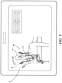
- the robotic system 10 may provide a message or notification 80, as shown in FIGS. 4 and 5 .
- the notification 80 aides the medical personnel during the surgical procedure.
- the notification 80 may be provided on any suitable medium, such as the user interface. In FIGS. 4 and 5 , the notification 80 is provided on the display 42 of the navigation system 32.
- the notification 80 may be provided by images, text, or a combination of images and text. Additionally, the notification 80 may be animated.
- the calculated characteristic is compared against a predetermined range of characteristics for optimal operation. If the calculated characteristic falls outside the range then the robotic system 10 may send the notification 80. For example, if the robotic system 10 determines the calculated characteristic, such as the stiffness characteristic (k), falls outside the range for optimal operation, then the robotic system 10 may send the notification 80 warning the medical personnel of that the calculated characteristic has fallen outside the range or that the surgical procedure should be halted. On the other hand, if the stiffness characteristic (k) falls within the range of optimal operating characteristics and the robotic system 10 may notify the medical personnel that the surgical procedure may continue. Additionally, the aforementioned embodiment may be realized during a calibration procedure. For example, the calibration procedure may terminate when the calculated characteristic falls within the range of optimal operating characteristics.
- the notification 80 may alert the medical personnel to reposition the anatomy in the surgical holder 14 such that the anatomy is more securely fastened. Repositioning of the anatomy is carried out by manipulating the surgical holder 14. As such, the notification 80 may suggest instructions on how to manipulate (e.g., move/adjust) the surgical holder 14.
- the position of the anatomy can be adjustably set along a plurality of degrees of freedom using the surgical holder 14.
- the force applied to the anatomy generates the response by the anatomy with respect to each degree of freedom. For each degree of freedom, the response of the anatomy is measured.
- the calculated characteristic is determined for each degree of freedom.
Landscapes
- Health & Medical Sciences (AREA)
- Life Sciences & Earth Sciences (AREA)
- Surgery (AREA)
- Engineering & Computer Science (AREA)
- Public Health (AREA)
- General Health & Medical Sciences (AREA)
- Animal Behavior & Ethology (AREA)
- Veterinary Medicine (AREA)
- Biomedical Technology (AREA)
- Heart & Thoracic Surgery (AREA)
- Medical Informatics (AREA)
- Molecular Biology (AREA)
- Nuclear Medicine, Radiotherapy & Molecular Imaging (AREA)
- Pathology (AREA)
- Biophysics (AREA)
- Physics & Mathematics (AREA)
- Robotics (AREA)
- Oral & Maxillofacial Surgery (AREA)
- Dentistry (AREA)
- Orthopedic Medicine & Surgery (AREA)
- Radiology & Medical Imaging (AREA)
- Physiology (AREA)
- Rheumatology (AREA)
- Manipulator (AREA)
- Rehabilitation Tools (AREA)
Applications Claiming Priority (4)
| Application Number | Priority Date | Filing Date | Title |
|---|---|---|---|
| US201361884500P | 2013-09-30 | 2013-09-30 | |
| EP14790844.6A EP3052043B1 (fr) | 2013-09-30 | 2014-09-30 | Système robotique pour manipuler l'anatomie d'un patient pendant une intervention chirurgicale |
| EP20205569.5A EP3821868B1 (fr) | 2013-09-30 | 2014-09-30 | Système pour commander un système robotique pour manipuler l'anatomie d'un patient pendant une intervention chirurgicale |
| PCT/US2014/058225 WO2015048714A1 (fr) | 2013-09-30 | 2014-09-30 | Système et procédé pour commander un système robotique pour manipuler l'anatomie d'un patient pendant une intervention chirurgicale |
Related Parent Applications (3)
| Application Number | Title | Priority Date | Filing Date |
|---|---|---|---|
| EP14790844.6A Division EP3052043B1 (fr) | 2013-09-30 | 2014-09-30 | Système robotique pour manipuler l'anatomie d'un patient pendant une intervention chirurgicale |
| EP20205569.5A Division-Into EP3821868B1 (fr) | 2013-09-30 | 2014-09-30 | Système pour commander un système robotique pour manipuler l'anatomie d'un patient pendant une intervention chirurgicale |
| EP20205569.5A Division EP3821868B1 (fr) | 2013-09-30 | 2014-09-30 | Système pour commander un système robotique pour manipuler l'anatomie d'un patient pendant une intervention chirurgicale |
Publications (2)
| Publication Number | Publication Date |
|---|---|
| EP4582071A2 true EP4582071A2 (fr) | 2025-07-09 |
| EP4582071A3 EP4582071A3 (fr) | 2025-10-15 |
Family
ID=51842790
Family Applications (3)
| Application Number | Title | Priority Date | Filing Date |
|---|---|---|---|
| EP25179260.2A Pending EP4582071A3 (fr) | 2013-09-30 | 2014-09-30 | Système robotique pour interaction avec une anatomie |
| EP14790844.6A Active EP3052043B1 (fr) | 2013-09-30 | 2014-09-30 | Système robotique pour manipuler l'anatomie d'un patient pendant une intervention chirurgicale |
| EP20205569.5A Active EP3821868B1 (fr) | 2013-09-30 | 2014-09-30 | Système pour commander un système robotique pour manipuler l'anatomie d'un patient pendant une intervention chirurgicale |
Family Applications After (2)
| Application Number | Title | Priority Date | Filing Date |
|---|---|---|---|
| EP14790844.6A Active EP3052043B1 (fr) | 2013-09-30 | 2014-09-30 | Système robotique pour manipuler l'anatomie d'un patient pendant une intervention chirurgicale |
| EP20205569.5A Active EP3821868B1 (fr) | 2013-09-30 | 2014-09-30 | Système pour commander un système robotique pour manipuler l'anatomie d'un patient pendant une intervention chirurgicale |
Country Status (8)
| Country | Link |
|---|---|
| US (4) | US10390737B2 (fr) |
| EP (3) | EP4582071A3 (fr) |
| JP (3) | JP6484226B2 (fr) |
| KR (4) | KR102484188B1 (fr) |
| CN (1) | CN105592817B (fr) |
| AU (5) | AU2014324557B2 (fr) |
| CA (1) | CA2924565A1 (fr) |
| WO (1) | WO2015048714A1 (fr) |
Families Citing this family (37)
| Publication number | Priority date | Publication date | Assignee | Title |
|---|---|---|---|---|
| US10368878B2 (en) | 2013-06-11 | 2019-08-06 | Orthotaxy | System for positioning a surgical device |
| US10390737B2 (en) | 2013-09-30 | 2019-08-27 | Stryker Corporation | System and method of controlling a robotic system for manipulating anatomy of a patient during a surgical procedure |
| US10507063B2 (en) * | 2014-11-21 | 2019-12-17 | Think Surgical, Inc. | Visible light communication system for transmitting data between visual tracking systems and tracking markers |
| CN105266869A (zh) * | 2015-10-26 | 2016-01-27 | 屠高良 | 一种用于骨科手术的打孔器固定装置 |
| US11229489B2 (en) | 2016-06-16 | 2022-01-25 | Zimmer, Inc. | Soft tissue balancing in articular surgery |
| US10136952B2 (en) * | 2016-06-16 | 2018-11-27 | Zimmer, Inc. | Soft tissue balancing in articular surgery |
| US10695134B2 (en) | 2016-08-25 | 2020-06-30 | Verily Life Sciences Llc | Motion execution of a robotic system |
| JP7170631B2 (ja) | 2016-10-05 | 2022-11-14 | ニューヴェイジヴ,インコーポレイテッド | 外科ナビゲーションシステム及び関連する方法 |
| WO2018112025A1 (fr) | 2016-12-16 | 2018-06-21 | Mako Surgical Corp. | Techniques pour modifier le fonctionnement d'un outil dans un système robotisé chirurgical sur la base de la comparaison des états réels et commandés de l'outil par rapport à un site chirurgical |
| US11432885B2 (en) * | 2017-12-28 | 2022-09-06 | Cilag Gmbh International | Sensing arrangements for robot-assisted surgical platforms |
| US11344374B2 (en) * | 2018-08-13 | 2022-05-31 | Verily Life Sciences Llc | Detection of unintentional movement of a user interface device |
| US11197728B2 (en) * | 2018-09-17 | 2021-12-14 | Auris Health, Inc. | Systems and methods for concomitant medical procedures |
| AU2020201097B2 (en) | 2019-02-14 | 2024-02-29 | Stryker Australia Pty Ltd | Systems for assisting surgery |
| WO2020225045A1 (fr) | 2019-05-03 | 2020-11-12 | Universiteit Gent | Positionnement d'implant osseux robotique spécifique à un patient |
| US11612440B2 (en) | 2019-09-05 | 2023-03-28 | Nuvasive, Inc. | Surgical instrument tracking devices and related methods |
| JP2021049198A (ja) * | 2019-09-25 | 2021-04-01 | 株式会社日立製作所 | 手術支援装置及び手術ナビゲーションシステム |
| EP4037581A1 (fr) | 2019-10-01 | 2022-08-10 | Mako Surgical Corp. | Systèmes chirurgicaux pour guider des manipulateurs robotiques |
| CN110638601B (zh) * | 2019-10-10 | 2021-11-23 | 南方医科大学第五附属医院 | 一种耳鼻喉综合诊疗台 |
| DK180673B1 (en) * | 2019-12-29 | 2021-11-25 | Universal Robots As | Method of obtaining vibrational properties of robot arm |
| WO2021235804A1 (fr) * | 2020-05-18 | 2021-11-25 | 주식회사 루닛 | Procédé et système de détermination d'anomalie de dispositif médical |
| JP7800010B2 (ja) * | 2020-07-20 | 2026-01-16 | ソニーグループ株式会社 | 医療用アーム制御システム、医療用アーム制御方法、及びプログラム |
| US12167984B2 (en) * | 2020-10-06 | 2024-12-17 | P Tech, Llc | Robotic systems, operating room systems, insulated conductor including biologically active material, microplastic filter, and combinations thereof |
| US12533805B2 (en) | 2020-10-30 | 2026-01-27 | Mako Surgical Corp. | Robotic surgical system with cut selection logic |
| US12167900B2 (en) | 2021-03-31 | 2024-12-17 | Moon Surgical Sas | Co-manipulation surgical system having automated preset robot arm configurations |
| US12042241B2 (en) | 2021-03-31 | 2024-07-23 | Moon Surgical Sas | Co-manipulation surgical system having automated preset robot arm configurations |
| JP2024513204A (ja) | 2021-03-31 | 2024-03-22 | ムーン サージカル エスアエス | 腹腔鏡下外科手術を実施するための外科手術用器具と併用するための協調操作式外科手術用システム |
| US11832909B2 (en) | 2021-03-31 | 2023-12-05 | Moon Surgical Sas | Co-manipulation surgical system having actuatable setup joints |
| US11844583B2 (en) | 2021-03-31 | 2023-12-19 | Moon Surgical Sas | Co-manipulation surgical system having an instrument centering mode for automatic scope movements |
| US11812938B2 (en) | 2021-03-31 | 2023-11-14 | Moon Surgical Sas | Co-manipulation surgical system having a coupling mechanism removeably attachable to surgical instruments |
| US11819302B2 (en) | 2021-03-31 | 2023-11-21 | Moon Surgical Sas | Co-manipulation surgical system having user guided stage control |
| US12178418B2 (en) | 2021-03-31 | 2024-12-31 | Moon Surgical Sas | Co-manipulation surgical system having a coupling mechanism removeably attachable to surgical instruments |
| CN114617649B (zh) * | 2022-03-09 | 2024-08-13 | 田义得 | 一种口腔科多功能牙钻组件 |
| WO2023205072A1 (fr) | 2022-04-18 | 2023-10-26 | Mako Surgical Corp. | Systèmes et procédés de placement guidé d'un manipulateur robotique |
| US11986165B1 (en) | 2023-01-09 | 2024-05-21 | Moon Surgical Sas | Co-manipulation surgical system for use with surgical instruments for performing laparoscopic surgery while estimating hold force |
| US11839442B1 (en) | 2023-01-09 | 2023-12-12 | Moon Surgical Sas | Co-manipulation surgical system for use with surgical instruments for performing laparoscopic surgery while estimating hold force |
| US12370001B2 (en) | 2023-01-09 | 2025-07-29 | Moon Surgical Sas | Co-manipulation surgical system having automated user override detection |
| WO2025006539A1 (fr) | 2023-06-30 | 2025-01-02 | Mako Surgical Corp. | Tenseur orthopédique motorisé et ses procédés d'utilisation |
Family Cites Families (30)
| Publication number | Priority date | Publication date | Assignee | Title |
|---|---|---|---|---|
| WO1991006245A1 (fr) | 1989-10-24 | 1991-05-16 | The Adelaide Bone And Joint Research Foundation Inc | Analyse osseuse par vibrations |
| US5086401A (en) | 1990-05-11 | 1992-02-04 | International Business Machines Corporation | Image-directed robotic system for precise robotic surgery including redundant consistency checking |
| US5339799A (en) | 1991-04-23 | 1994-08-23 | Olympus Optical Co., Ltd. | Medical system for reproducing a state of contact of the treatment section in the operation unit |
| US6704959B2 (en) * | 2001-08-13 | 2004-03-16 | Peter Schuerch | Adjustable position limb support for surgical tables |
| US7708741B1 (en) * | 2001-08-28 | 2010-05-04 | Marctec, Llc | Method of preparing bones for knee replacement surgery |
| US8010180B2 (en) * | 2002-03-06 | 2011-08-30 | Mako Surgical Corp. | Haptic guidance system and method |
| US7747311B2 (en) | 2002-03-06 | 2010-06-29 | Mako Surgical Corp. | System and method for interactive haptic positioning of a medical device |
| US7831292B2 (en) * | 2002-03-06 | 2010-11-09 | Mako Surgical Corp. | Guidance system and method for surgical procedures with improved feedback |
| JP4285083B2 (ja) * | 2003-05-27 | 2009-06-24 | パナソニック電工株式会社 | マッサージ機 |
| CA2826925C (fr) | 2005-02-22 | 2017-01-24 | Mako Surgical Corp. | Systeme de guidage haptique et procede |
| US8117695B2 (en) * | 2005-05-17 | 2012-02-21 | Ohad Paz | Multi-position support apparatus featuring a movable foot support |
| JP2007202950A (ja) * | 2006-02-06 | 2007-08-16 | Nakashima Propeller Co Ltd | 手術ロボット用下肢把持治具 |
| AU2007254159B2 (en) | 2006-05-19 | 2013-07-04 | Mako Surgical Corp. | System and method for verifying calibration of a surgical device |
| CA2654343C (fr) | 2006-06-05 | 2015-02-10 | Technion Research & Development Foundation Ltd. | Guidage controle d'une aiguille flexible |
| US8374673B2 (en) * | 2007-01-25 | 2013-02-12 | Warsaw Orthopedic, Inc. | Integrated surgical navigational and neuromonitoring system having automated surgical assistance and control |
| US20080249394A1 (en) * | 2007-04-03 | 2008-10-09 | The Board Of Trustees Of The Leland Stanford Junior University | Method for improved rotational alignment in joint arthroplasty |
| EP2164419A1 (fr) * | 2007-11-08 | 2010-03-24 | Orthosoft, Inc. | Dispositif de référence pouvant être suivi pour chirurgie assistée par ordinateur |
| CN104382650B (zh) * | 2008-05-28 | 2017-04-12 | 泰克尼恩研究和发展基金有限公司 | 用于柔性针操纵的超声引导机器人 |
| US20110301500A1 (en) | 2008-10-29 | 2011-12-08 | Tim Maguire | Automated vessel puncture device using three-dimensional(3d) near infrared (nir) imaging and a robotically driven needle |
| CN102802552B (zh) * | 2009-05-27 | 2015-11-25 | 新特斯有限责任公司 | 机械臂 |
| JP2011254975A (ja) | 2010-06-09 | 2011-12-22 | Nakashima Medical Co Ltd | 手術支援システム |
| JP5707758B2 (ja) | 2010-07-13 | 2015-04-30 | ソニー株式会社 | 撮像装置、撮像システム、手術用ナビゲーションシステム、及び撮像方法 |
| US9119655B2 (en) | 2012-08-03 | 2015-09-01 | Stryker Corporation | Surgical manipulator capable of controlling a surgical instrument in multiple modes |
| KR101181613B1 (ko) | 2011-02-21 | 2012-09-10 | 윤상진 | 사용자 지정에 따라 결정되는 변위 정보에 기초하여 수술을 수행하는 수술용 로봇 시스템과 그 제어 방법 |
| EP2734168B1 (fr) | 2011-07-22 | 2015-09-16 | Stryker Corporation | Support de membre multi-positions |
| US9228885B2 (en) * | 2012-06-21 | 2016-01-05 | Hill-Rom Services, Inc. | Patient support systems and methods of use |
| US9008757B2 (en) | 2012-09-26 | 2015-04-14 | Stryker Corporation | Navigation system including optical and non-optical sensors |
| WO2014164207A1 (fr) | 2013-03-12 | 2014-10-09 | Stryker Corporation | Ensemble capteur et procédé permettant de mesurer des forces et des couples |
| US9566022B2 (en) * | 2013-03-14 | 2017-02-14 | Hospital For Special Surgery | Apparatus and method for determining 3D load displacement response of a joint |
| US10390737B2 (en) | 2013-09-30 | 2019-08-27 | Stryker Corporation | System and method of controlling a robotic system for manipulating anatomy of a patient during a surgical procedure |
-
2014
- 2014-09-29 US US14/500,280 patent/US10390737B2/en active Active
- 2014-09-30 KR KR1020227004832A patent/KR102484188B1/ko active Active
- 2014-09-30 CA CA2924565A patent/CA2924565A1/fr not_active Abandoned
- 2014-09-30 EP EP25179260.2A patent/EP4582071A3/fr active Pending
- 2014-09-30 KR KR1020227046255A patent/KR102626744B1/ko active Active
- 2014-09-30 AU AU2014324557A patent/AU2014324557B2/en active Active
- 2014-09-30 JP JP2016518078A patent/JP6484226B2/ja active Active
- 2014-09-30 EP EP14790844.6A patent/EP3052043B1/fr active Active
- 2014-09-30 KR KR1020167008706A patent/KR102364888B1/ko active Active
- 2014-09-30 EP EP20205569.5A patent/EP3821868B1/fr active Active
- 2014-09-30 KR KR1020247001329A patent/KR102770570B1/ko active Active
- 2014-09-30 CN CN201480053882.6A patent/CN105592817B/zh active Active
- 2014-09-30 WO PCT/US2014/058225 patent/WO2015048714A1/fr not_active Ceased
-
2019
- 2019-02-14 JP JP2019024256A patent/JP6880090B2/ja active Active
- 2019-07-11 US US16/508,790 patent/US11406284B2/en active Active
- 2019-09-13 AU AU2019229454A patent/AU2019229454B2/en active Active
-
2021
- 2021-04-30 JP JP2021077282A patent/JP7200291B2/ja active Active
- 2021-08-06 AU AU2021212127A patent/AU2021212127B2/en active Active
-
2022
- 2022-06-29 US US17/852,440 patent/US12419542B2/en active Active
-
2023
- 2023-11-16 AU AU2023266336A patent/AU2023266336B2/en active Active
-
2025
- 2025-08-19 US US19/303,918 patent/US20260083353A1/en active Pending
- 2025-11-25 AU AU2025271222A patent/AU2025271222A1/en active Pending
Also Published As
Similar Documents
| Publication | Publication Date | Title |
|---|---|---|
| AU2023266336B2 (en) | System and method of controlling a robotic system for manipulating anatomy of a patient during a surgical procedure | |
| US12144565B2 (en) | Optical and non-optical sensor tracking of a robotically controlled instrument | |
| EP3052042B1 (fr) | Système pour interagir avec un objet | |
| CN101448467B (zh) | 用于控制触觉设备的方法和装置 |
Legal Events
| Date | Code | Title | Description |
|---|---|---|---|
| PUAI | Public reference made under article 153(3) epc to a published international application that has entered the european phase |
Free format text: ORIGINAL CODE: 0009012 |
|
| STAA | Information on the status of an ep patent application or granted ep patent |
Free format text: STATUS: THE APPLICATION HAS BEEN PUBLISHED |
|
| AC | Divisional application: reference to earlier application |
Ref document number: 3052043 Country of ref document: EP Kind code of ref document: P Ref document number: 3821868 Country of ref document: EP Kind code of ref document: P |
|
| AK | Designated contracting states |
Kind code of ref document: A2 Designated state(s): AL AT BE BG CH CY CZ DE DK EE ES FI FR GB GR HR HU IE IS IT LI LT LU LV MC MK MT NL NO PL PT RO RS SE SI SK SM TR |
|
| REG | Reference to a national code |
Ref country code: DE Ref legal event code: R079 Free format text: PREVIOUS MAIN CLASS: A61G0013060000 Ipc: A61G0013120000 |
|
| PUAL | Search report despatched |
Free format text: ORIGINAL CODE: 0009013 |
|
| AK | Designated contracting states |
Kind code of ref document: A3 Designated state(s): AL AT BE BG CH CY CZ DE DK EE ES FI FR GB GR HR HU IE IS IT LI LT LU LV MC MK MT NL NO PL PT RO RS SE SI SK SM TR |
|
| RIC1 | Information provided on ipc code assigned before grant |
Ipc: A61G 13/12 20060101AFI20250905BHEP Ipc: A61B 34/30 20160101ALI20250905BHEP Ipc: A61B 34/32 20160101ALI20250905BHEP Ipc: A61G 13/00 20060101ALN20250905BHEP Ipc: A61B 90/00 20160101ALN20250905BHEP Ipc: A61G 13/06 20060101ALN20250905BHEP Ipc: A61G 13/10 20060101ALN20250905BHEP Ipc: A61B 34/20 20160101ALN20250905BHEP Ipc: A61B 5/00 20060101ALN20250905BHEP |
|
| STAA | Information on the status of an ep patent application or granted ep patent |
Free format text: STATUS: REQUEST FOR EXAMINATION WAS MADE |