EP4582113A2 - Systèmes, cathéters et procédés de traitement le long du système nerveux central - Google Patents
Systèmes, cathéters et procédés de traitement le long du système nerveux central Download PDFInfo
- Publication number
- EP4582113A2 EP4582113A2 EP25177734.8A EP25177734A EP4582113A2 EP 4582113 A2 EP4582113 A2 EP 4582113A2 EP 25177734 A EP25177734 A EP 25177734A EP 4582113 A2 EP4582113 A2 EP 4582113A2
- Authority
- EP
- European Patent Office
- Prior art keywords
- pump
- timer
- controller
- filter
- pressure
- Prior art date
- Legal status (The legal status is an assumption and is not a legal conclusion. Google has not performed a legal analysis and makes no representation as to the accuracy of the status listed.)
- Pending
Links
Images



Classifications
-
- A—HUMAN NECESSITIES
- A61—MEDICAL OR VETERINARY SCIENCE; HYGIENE
- A61M—DEVICES FOR INTRODUCING MEDIA INTO, OR ONTO, THE BODY; DEVICES FOR TRANSDUCING BODY MEDIA OR FOR TAKING MEDIA FROM THE BODY; DEVICES FOR PRODUCING OR ENDING SLEEP OR STUPOR
- A61M27/00—Drainage appliance for wounds or the like, i.e. wound drains, implanted drains
- A61M27/002—Implant devices for drainage of body fluids from one part of the body to another
- A61M27/006—Cerebrospinal drainage; Accessories therefor, e.g. valves
-
- A—HUMAN NECESSITIES
- A61—MEDICAL OR VETERINARY SCIENCE; HYGIENE
- A61M—DEVICES FOR INTRODUCING MEDIA INTO, OR ONTO, THE BODY; DEVICES FOR TRANSDUCING BODY MEDIA OR FOR TAKING MEDIA FROM THE BODY; DEVICES FOR PRODUCING OR ENDING SLEEP OR STUPOR
- A61M1/00—Suction or pumping devices for medical purposes; Devices for carrying-off, for treatment of, or for carrying-over, body-liquids; Drainage systems
- A61M1/71—Suction drainage systems
- A61M1/74—Suction control
-
- A—HUMAN NECESSITIES
- A61—MEDICAL OR VETERINARY SCIENCE; HYGIENE
- A61M—DEVICES FOR INTRODUCING MEDIA INTO, OR ONTO, THE BODY; DEVICES FOR TRANSDUCING BODY MEDIA OR FOR TAKING MEDIA FROM THE BODY; DEVICES FOR PRODUCING OR ENDING SLEEP OR STUPOR
- A61M1/00—Suction or pumping devices for medical purposes; Devices for carrying-off, for treatment of, or for carrying-over, body-liquids; Drainage systems
- A61M1/88—Draining devices having means for processing the drained fluid, e.g. an absorber
-
- A—HUMAN NECESSITIES
- A61—MEDICAL OR VETERINARY SCIENCE; HYGIENE
- A61M—DEVICES FOR INTRODUCING MEDIA INTO, OR ONTO, THE BODY; DEVICES FOR TRANSDUCING BODY MEDIA OR FOR TAKING MEDIA FROM THE BODY; DEVICES FOR PRODUCING OR ENDING SLEEP OR STUPOR
- A61M2202/00—Special media to be introduced, removed or treated
- A61M2202/04—Liquids
- A61M2202/0464—Cerebrospinal fluid
-
- A—HUMAN NECESSITIES
- A61—MEDICAL OR VETERINARY SCIENCE; HYGIENE
- A61M—DEVICES FOR INTRODUCING MEDIA INTO, OR ONTO, THE BODY; DEVICES FOR TRANSDUCING BODY MEDIA OR FOR TAKING MEDIA FROM THE BODY; DEVICES FOR PRODUCING OR ENDING SLEEP OR STUPOR
- A61M2205/00—General characteristics of the apparatus
- A61M2205/33—Controlling, regulating or measuring
- A61M2205/3331—Pressure; Flow
-
- A—HUMAN NECESSITIES
- A61—MEDICAL OR VETERINARY SCIENCE; HYGIENE
- A61M—DEVICES FOR INTRODUCING MEDIA INTO, OR ONTO, THE BODY; DEVICES FOR TRANSDUCING BODY MEDIA OR FOR TAKING MEDIA FROM THE BODY; DEVICES FOR PRODUCING OR ENDING SLEEP OR STUPOR
- A61M2205/00—General characteristics of the apparatus
- A61M2205/33—Controlling, regulating or measuring
- A61M2205/3331—Pressure; Flow
- A61M2205/3334—Measuring or controlling the flow rate
-
- A—HUMAN NECESSITIES
- A61—MEDICAL OR VETERINARY SCIENCE; HYGIENE
- A61M—DEVICES FOR INTRODUCING MEDIA INTO, OR ONTO, THE BODY; DEVICES FOR TRANSDUCING BODY MEDIA OR FOR TAKING MEDIA FROM THE BODY; DEVICES FOR PRODUCING OR ENDING SLEEP OR STUPOR
- A61M2205/00—General characteristics of the apparatus
- A61M2205/33—Controlling, regulating or measuring
- A61M2205/3331—Pressure; Flow
- A61M2205/3355—Controlling downstream pump pressure
-
- A—HUMAN NECESSITIES
- A61—MEDICAL OR VETERINARY SCIENCE; HYGIENE
- A61M—DEVICES FOR INTRODUCING MEDIA INTO, OR ONTO, THE BODY; DEVICES FOR TRANSDUCING BODY MEDIA OR FOR TAKING MEDIA FROM THE BODY; DEVICES FOR PRODUCING OR ENDING SLEEP OR STUPOR
- A61M2205/00—General characteristics of the apparatus
- A61M2205/75—General characteristics of the apparatus with filters
Definitions
- the present disclosure relates to systems, catheters, and methods for treating along the central nervous system.
- a wide variety of medical devices have been developed for medical use. Some of these devices include guidewires, catheters, and the like. These devices are manufactured by any one of a variety of different manufacturing methods and may be used according to any one of a variety of methods. Of the known medical devices and methods, each has certain advantages and disadvantages. There is an ongoing need to provide alternative medical devices as well as alternative methods for manufacturing and using medical devices.
- a cerebrospinal fluid flow control system may include a pump configured to pump cerebrospinal fluid along a fluid circuit, a fluid line in communication with the pump, the fluid line having an inlet configured to receive cerebrospinal fluid from a patient, an outlet configured to provide conditioned cerebrospinal fluid to the patient, and a lumen configured to facilitate travel of cerebrospinal fluid along the fluid circuit from the inlet of the fluid line to the pump and from the pump to the outlet of the fluid line, a sensor in communication with the lumen of the fluid line, the sensor is configured to sense a measure related to a pressure in the lumen of the fluid line at a location downstream of the pump, a controller in communication with the sensor and the pump. The controller may be configured to control operation of the pump based on the measure sensed by the sensor.
- the controller may be configured to control operation of the pump based on a delta value based on the measure sensed by the sensor, the delta value is a difference between a value based on the measure sensed by the sensor at a time T and a value based on the measure sensed by the sensor at a previous time of the time T minus a time interval N.
- the time interval N may be equal to five minutes.
- controller may be configured to control operation of the pump according to a first control protocol when the value based on the measure sensed by the sensor at time T has not reached a threshold value, and a second control protocol when the value based on the measure sensed by the sensor at time T has reached or gone beyond the threshold value, the second control protocol is different than the first control protocol.
- the controller may be configured to determine the threshold value based on the delta value.
- the controller may be configured to adjust the threshold value based on a length of continuous time the pump has been operating.
- the controller may be configured such that when controlling operation of the pump according to the first control protocol, the threshold value is a first threshold value and the controller compares the value based on the measure sensed by the sensor to a second threshold value, the second threshold value is based on the delta value.
- the controller may increase a pumping rate of the pump by a first predetermined amount.
- the controller may increase the pumping rate of the pump by a second predetermined amount.
- the system may include a timer timing an amount of time the controller has been controlling operation of the pump according to the first control protocol, and when the controller increases the pumping rate of the pump one of the first predetermined amount and the second predetermined amount and the increase in the pumping rate is equal to or less than zero, the controller may be configured to stop the timer and re-calculate the delta value.
- the controller when the controller increases the pumping rate of the pump one of the first predetermined amount and the second predetermined amount and the increase in the pumping rate is greater than zero, the controller may be configured to determine whether the timer is running, and when the controller determines the timer is not running, the controller is configured to start the timer and recalculate the delta value.
- the system may further include a timer and when controlling operation of the pump according to the second control protocol, the timer may be configured to time an amount of time the controller has been controlling operation of the pump according to the second control protocol; the controller determines whether the timer is running; and when the controller determines the timer is not running, the controller may be configured to start the timer and recalculate the delta value.
- the controller when the controller determines the timer is running, the controller is configured to determine whether the timer has expired; when the controller determines the timer has not expired, the controller may be configured to recalculate the delta value; and when the controller determines the timer has expired, the controller may be configured to decrease a pumping rate of the pump by a predetermined amount.
- the controller when the controller determines the timer has expired, the controller may be configured to restart the timer.
- the system may further comprise a timer timing an amount of time the controller has been controlling operation of the pump according to the first control protocol; and when the controller increases the pumping rate of the pump by one of the first predetermined amount and the second predetermined amount and the increase in the pumping rate is equal to or less than zero, the controller may be configured to stop the timer and re-calculate the delta value.
- a method of controlling cerebrospinal fluid flow through a cerebrospinal fluid filtering module may comprise pumping cerebrospinal fluid through a filter module with a pump at a pumping rate via a fluid line, the fluid line having an inlet configured to receive cerebrospinal fluid from a patient, an outlet configured to provide filtered cerebrospinal fluid to the patient from the filter module, and a lumen configured to facilitate travel of cerebrospinal fluid from the inlet of the fluid line to the filter module and from the filter module to the outlet of the fluid line, sensing a measure related to a pressure in the lumen of the fluid line at a location upstream of the filter module; and controlling operation of the pump in an automated manner based on one or both of a value based on the measure related to a pressure in the lumen of the fluid line sensed at a location upstream of the filter module and a delta value, the delta value is a difference between the value based on the measure related to a pressure in the lumen of the fluid line
- controlling operation of the pump in an automated matter may comprise controlling operation of the pump according to a first control protocol when the value based on the measure related to a pressure in the lumen of the fluid line at the time T has not reached a threshold; and controlling operation of the pump according to a second control protocol when the value based on the measure related to a pressure in the lumen of the fluid line at the time T has reached or gone beyond the threshold, the first control protocol is different than the second control protocol.
- the method may further comprise determine in an automated manner the threshold based on the delta value.
- the threshold when controlling operation of the pump according to the first control protocol, the threshold may be a first threshold value and the method may further comprise comparing the value based on the measure related to a pressure in the lumen of the fluid line at the time T to a second threshold value, the second threshold value is based on the delta value; when the value based on the measure related to a pressure in the lumen of the fluid line at the time T has not reached or gone beyond the second threshold value, increasing a pumping rate of the pump by a first predetermined amount; and when the value based on the measure related to a pressure in the lumen of the fluid line at the time T has reached or gone beyond the second threshold value, increasing the pumping rate of the pump by a second predetermined amount.
- the method may further comprise timing in an automated manner with a timer an amount of time the pump has been controlled according to the first control protocol; and when pumping rate of the pump has been increased by one of the first predetermined amount and the second predetermined amount and the increase in the pumping rate is equal to or less than zero, stopping the timing of the amount of time the pump has been controlled according to the first control protocol and recalculating the delta value
- the timer may be a first timer and the method may further comprise timing with a second timer an amount of time the pump has been controlled according to the second control protocol; determining whether the second timer is running, the second timer is configured to time an amount of time the pump has been controlled according to the second control protocol; and starting the second timer and recalculating the delta value when the second timer is determined to be not running.
- the method may further comprise determining whether the second timer has expired after the second timer has been determined to be running; recalculating the delta value when the second timer has been determined to not have expired; and when it has been determined the second timer has expired, decreasing the pumping rate by a third predetermined amount.
- the method may further comprise recalculating the delta value after restarting the second timer.
- the method may further comprise determining the third predetermined amount based on the delta value.
- the method may further comprise determining the third predetermined amount based on a percentage value of the pumping rate of the pump.
- the method may further comprise when the timer has been determined to be running, determining whether the timer has expired; when the timer has been determined to have not expired, recalculating the delta value; and when the timer has been determined to have expired, decreasing the pumping rate by a predetermined amount.
- the method may further comprise sensing a measure related to a pressure in the lumen of the fluid line at a location upstream of the pump and the filter module; and shutting down the pump when a value based on the measure related to the pressure in the lumen of the fluid line at a location upstream of the pump and the filter module has reached or gone beyond a predetermined value.
- the method may further comprise sensing a measure related to a pressure in the lumen of the fluid line at a location downstream of the pump and the filter module; and shutting down the pump when a value based on the measure related to the pressure in the lumen of the fluid line at a location downstream of the pump and the filter module has reached or gone beyond a predetermined threshold.
- controlling operation of the pump in an automated manner may include controlling operation of the pump using a control loop that is repeated over time.
- a computer readable medium having stored thereon in a non-transitory state a program code for use by a computing device, the program code causing the computing device to execute a method for controlling fluid flow through a cerebrospinal fluid filtering module.
- the method may comprise: outputting a control signal to a pump to pump cerebrospinal fluid through a filter module via a fluid line; determining a value based on a measure related to a pressure in a lumen of the fluid line at a location upstream of the filter module; and configuring the control signal to adjust a pumping rate of the pump, wherein the configuring the control signal is based on one or both of the value based on the measure related to a pressure in the lumen of the fluid line at the location upstream of the filter module and a delta value, the delta value is a difference between the value based on the measure related to a pressure in the lumen of the fluid line sensed at a location upstream of the filter module at a time T and the value based on the measure related
- configuring the control signal may comprise configuring the control signal according to a first control protocol when the value based on the measure related to a pressure in the lumen of the fluid line at the time T has not reached a threshold; and configuring the control signal according to a second control protocol when the value based on the measure related to a pressure in the lumen of the fluid line at the time T has reached or gone beyond the threshold, the first control protocol is different than the second control protocol.
- the method may further comprise determining in an automated manner the threshold based on the delta value.
- the method may further comprise adjusting the threshold in an automated manner based on a length of continuous time the pump has been operating.
- the threshold may be a first threshold value and configuring the control signal according to the first control protocol may comprise: comparing the value based on the measure related to a pressure in the lumen of the fluid line at the time T to a second threshold value, the second threshold value is based on the delta value; when the value based on the measure related to a pressure in the lumen of the fluid line at the time T has not reached or gone beyond the second threshold value, increasing a pumping rate of the pump by a first predetermined amount; and when the value based on the measure related to a pressure in the lumen of the fluid line at the time T has reached or gone beyond the second threshold value, increasing the pumping rate of the pump by a second predetermined amount.
- the method may further comprise determining in an automated manner the first predetermined amount and the second predetermined amount based on the delta value.
- the method may further comprise: timing in an automated manner with a timer an amount of time the pump has been controlled according to the first control protocol; and stopping timing the amount of time the pump has been controlled according to the first control protocol and recalculating the delta value when increasing the pumping rate of the pump by one of the first predetermined amount and the second predetermined amount and the increase in the pumping rate is equal to or less than zero.
- the method may further comprise: determining whether the timer is running; and starting the timer and recalculating the delta value when the timer is determined to be not running.
- the method may further comprise restarting the second timer when second timer has been determined to have expired.
- the CSF traveling through the pump/filtration system 100 may travel along the fluid circuit through various pathways as described herein (e.g., pathways 102, 106, etc.) via a fluid line having a lumen therein (e.g., tubing or other suitable mechanism forming a lumen and configured to facilitate maintaining a desired pressure within the fluid circuit by fluid tight connections at connection points, if any), where the lumen may be configured to facilitate travel of CSF along the fluid circuit from an inlet of the fluid line to the pump 104 and from the pump 104 to an outlet of the fluid line.
- a lumen e.g., tubing or other suitable mechanism forming a lumen and configured to facilitate maintaining a desired pressure within the fluid circuit by fluid tight connections at connection points, if any
- the sensor 108 may be any suitable sensor configured to sense a measure related to a pressure in a lumen of a fluid line between the pathway 106 and a pathway 110.
- the sensor 108 and/or other sensors described herein as being configured to sense a measure related to pressure may be a pressure sensor, a flow sensor, or other suitable sensor for sensing a measure related to a pressure in the lumen of the fluid line.
- the sensor 108 may be a pressure sensor in communication (e.g., direct communication and/or indirect communication, such as through a wall of the of the fluid line) with the lumen of the fluid line and configured to sense a measure related to a pressure in the lumen of the fluid line at a location downstream of the pump 104.
- Example pressure sensors include any suitable type of pressure sensor element.
- the pressure sensor elements may be MEMS (Micro Electro Mechanical Systems) pressure sensor elements such as an absolute pressure sense element, a gauge pressure sense element, or other pressure sense element as desired.
- the fluid may flow from the sensor 108 along the pathway 110 to a filter module 112.
- the filter module 112 may have one or more filters.
- the filter module 112 may have a first filter 114 and a second filter 116.
- the first filter 114 and/or the second filter 116 may each be a tangential flow filter (TFF) or other suitable type of filter.
- the first filter 114 and/or the second filter 116 may include a 5kDa TFF, a 100kDa TFF, a 0.2 ⁇ m TFF, a 0.45 ⁇ m TFF, or the like.
- the waste control mechanism 136 may control a rate at which waste CSF is passed along a waste outlet pathway 138 to a collection apparatus 140 for disposal (e.g., a rate at which the waste CSF is outputted from the filter module 112).
- the waste control mechanism may be controlled manually and/or in an automated manner.
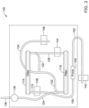
- FIG. 2 depicts a further schematic illustration of the pump/filtration system 100 depicting fluid lines along pathways between components of the pump/filtration system 100 (e.g., pathways 102, 106, 110, 122, 124, 126, 132, 134, 136, 138) to transfer CSF through the pump/filtration system 100.
- components of the pump/filtration system 100 e.g., pathways 102, 106, 110, 122, 124, 126, 132, 134, 136, 138
- four (4) sensors are utilized to facilitate control of the pump/filtration system 100.
- a sensor 142 may be located upstream of the pump 104 to sense a measure related to a pump/filtration system inlet pressure in a fluid line at pathway 102
- the sensor 108 may be located downstream of the pump 104 and upstream of the first filter 114 to sense a measure related to a first filter inlet pressure in a fluid line adjacent pathways 106, 110
- a sensor 144 e.g., a pressure sensor or other sensor configured to sense a parameter related to pressure
- a fourth sensor 146 e.g., a pressure sensor or other sensor configured to sense a parameter related to pressure
- a fourth sensor 146 may be located downstream of the second filter 116 to sense a measure related to a pump/filtration system outlet pressure adjacent
- FIG. 3 illustrates an embodiment of a catheter 200 that may be utilized with the pump/filtration system 100.
- catheter 200 is described herein, additional descriptions of example catheters that may be used with the pump/filtration system 100 for pumping and/or filtering CSF are described in U.S Patent Application Serial No. 62/286,413 (Attorney docket number 1421.1010120) filed on June 18, 2018 , and titled "SYSTEMS, CATHETERS, AND METHODS FOR TREATING ALONG THE CENTRAL NERVOUS SYSTEM", which is hereby incorporated by reference for all purposes.
- the length L 1 of the catheter 200 may be approximately 1,300 mm with a working length L 2 of approximately 1,150 mm.
- the working length L 2 may be defined based on various use and design considerations. As illustrated, the working length L 2 is the distance from the distal end of the distal subassembly 260 to the distal end of the feature 208. The distance Di from the distal end of the feature 208 to the proximal end of the connector 206 may be approximately 150 mm.
- the feature 208 may have a length L 3 of approximately 35 mm and the features 210, 212 may have a length L 4 of approximately 7 mm.
- the catheter 200 may have a length L 1 of between approximately 400 mm and approximately 1200 mm, with the working length L 2 and other measurements changed accordingly at varying scales.
- the catheter 200 may be disposed within the cerebrospinal space (e.g., such as along lumbar cerebrospinal space). CSF may be removed/aspirated using the catheter 200, the pump/filtration system 100, and/or the flow control process 300. The aspirated fluid may be filtered using the pump/filtration system 100 and the flow control process 300 and the filtered/conditioned CSF may be returned to the patient using the catheter 200, the pump/filtration system 100, and the flow control process 300.
- a second catheter 200 (that may be similar in form and function to the catheter 200) may be disposed in a portion of the cranial CNS such as within a ventricle.
- the second catheter 200 may be used to remove/aspirate cerebrospinal fluid from a cranial region (e.g., a ventricle), condition/filter the cerebrospinal fluid using the pump/filtration system 100, and return the conditioned/filtered cerebrospinal fluid to a region at or adjacent to the cranial region.
- the second catheter 200 may be used to infuse a drug (e.g., a chemotherapy drug such as methotrexate) into the cranial region.
- the catheter 200 e.g., in the cerebrospinal space
- the second catheter 200 in the ventricle
- Using a catheter 200 in both the cerebrospinal space and in the ventricle, both for aspiration and of the infusion, may form a cranial-lumbar loop that may improve circulation of cerebrospinal fluid throughout the CNS.
- FIG. 4 depicts a schematic control system 150 for the pump/filtration system 100.
- the schematic control system 150 may include a controller 152, the pump 104 in communication with the controller 152, a pressure sensing module 154 in communication with the controller 152, a user interface 156 in communication with the controller 152, and/or one or more other components or systems.
- the pressure sensing module 154 and the user interface 156 when included, may communicate directly with one another, but this is not required.
- the controller 152 may include one or more components.
- the controller 152 may include a processor 158, memory 160 in communication with the processor 158, input/output (I/O) ports 162 in communication with the processor 158 and/or the memory 160, and/or one or more other suitable components of the control system 150.
- I/O input/output
- the memory 160 may be or may include non-transitory computer readable medium that may include or may be programed to include software or other instructions to be executed by the processor 158 and facilitate the controller 152 operating in an automated manner to output control signals via the I/O ports 162 to the pump 104 and/or the waste control mechanism 136 based on input received at the I/O ports 162 from the pressure sensing module 154 and/or the user interface 156 for the purposes of optimizing a flow rate through the pump/filtration system 100 while maintaining filter pressures within a desired range and/or for other desired purposes.
- controller 152 may be configured to receive information from the pump 104 and/or the waste control mechanism 136 and/or output control signals to the pressure sensing module 154 and/or the user interface 156.
- the processor 158 may include a single processor or more than one processor working individually or with one another.
- Example processor components may include, but are not limited to microprocessors, microcontrollers, multi-core processors, graphical processing units, and/or other suitable processors.
- the memory 160 may include a single memory component or more than one memory components working individually or with one another.
- Example types of memory may include RAM, ROM, EEPROM, FLASH, other volatile or non-volatile memory, or any other suitable memory for the controller 152.
- the memory 160 may be or may include non-transitory computer readable medium.
- the I/O ports 162 may be any type of communication port configured to communicate with the pressure sensing module 154, the user interface 156, the pump 104, the waste control mechanism 136, and/or one or more other components of the pump/filtration system 100.
- Example I/O port types may include wired ports, wireless ports, radio frequency (RF) ports, Bluetooth ports, Near-Field Communication (NFC) ports, HDMI ports, Ethernet ports, VGA ports, serial ports, parallel ports, component video ports, S-video ports, composite audio/video ports, DVI ports, USB ports, optical ports, and/or other suitable ports.
- RF radio frequency
- NFC Near-Field Communication
- the pressure sensing module 154 may include one or more of the sensors 108, 142, 144, 146 discussed above and/or other sensors configured to sense a measure related to a pressure in a lumen of a fluid line. In one example, the pressure sensing module 154 may send readings from one or more of the sensors 108, 142, 144, 146 to the controller 152 and the processor 158 may output a control signal to the pump 104 and/or the waste control mechanism 136 based on the received readings.
- the user interface 156 may be any suitable type of user interface configured to facilitate a user interacting with the pump/filtration system 100.
- the user interface 156 may include a work station, a computer, a computing device, a tablet computer, a phone, a display, a keypad, a touch screen, a mouse, and/or one or more other suitable components that facilitate a user interacting with the pump/filtration system 100.
- the control system 150 may be configured to send control signals to the waste control mechanism 136 to control operation of the waste control mechanism 136.
- the control system 150 may utilize a flow control process to optimize a flow rate of fluid through the waste control mechanism 136 to optimize waste removal from the filter module 112.
- the control system 150 may be configured to send a control signal to the waste control mechanism 136 to shut down the waste control mechanism if a value related to a measure received from the pressure sensing module reaches or goes beyond a threshold level.
- the control system 150 may be configured to send control signals to the pump 104 to control operation of the pump 104.
- the control system 150 may utilize a flow control process to optimize a pump rate of the pump 104 to maximize fluid flow through the pump/filtration system 100 while accommodating a time varying nature of contaminants (e.g., a consistency or material make-up of CSF may change over time) and keeping a filter pressure (e.g., a filter pressure measured upstream of the filter module 112 or other suitable filter pressure) within desired boundaries.
- the control flow utilized by the control system may operate without having a designated optimal pump rate set point for the pump 104 and/or without having an optimal filter pressure set point. As filter pressure may be proportional to the concentration of contaminants in CSF within the filter module 112, not utilizing an optimal filter pressure set point facilitates using the control flow to pump and filter CSF due to the contaminant concentration in CSF varying over time.
- the flow control process 300 may begin with a start 302 of the flow control process 300.
- the flow control process 300 may include an initiation phase configured to initiate the pump/filtration system 100 and then move to the start 302 of the flow control process 300.
- an initiation phase configured to initiate the pump/filtration system 100 may be separate from the flow control process 300.
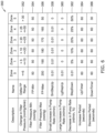
- Zone zero (0) may have a range from 0 to five (5) mmHg/5 min (e.g., per N units of time)
- Zone one (1) may have range from greater than five (5) to ten (10) mm Hg/5 min
- Zone two (2) may have a range from greater than ten (10) to twenty (20) mm Hg/5 min
- Zone three (3) may have a range from greater than twenty (20) to twenty-five (25) mm Hg/5 min
- Zone four (4) may have a range from greater than twenty-five (25) to thirty (30) mm Hg/5 min
- Zone five (5) may have range of all changes in pressure greater than thirty (30) mm Hg/5 min.
- zone 0 may be considered a "stable zone", but this is not required.
- the flow control table 350 may be saved in the memory 160 of the controller 152 or other memory and accessed by the processor 158. In some cases, the flow control table 350 may be a look-up table, but this is not required. In some case, the flow control table 350 may be in a format other than a table that facilitates associating various zones for the pump/filtration system 100 with various parameters related to the operation of the pump/filtration system 100. Although the flow control table 350 depicts zones associated with control parameters, the flow control table 350 include additional and/or alternative parameters associated with the zones and/or changes in filter pressure or other pressures over time.
- Pump rate adjustments to be used in the flow control process 300 may be determined 312 for the determined zone.
- the pump rate adjustments may be found in rows 358, 360, and 362 of the flow control table 350.
- the row 358 of the flow control table may provide values for a "small increase in pump rate”
- the row 360 of the flow control table 350 may provide values for a "large increase in pump rate”
- the row 362 of the flow control table 350 may provide values for a "decrease in pump rate”.
- a small increase in pump rate may be 0.01 ml/min for Zones zero (0) through four (4) and zero (0) ml/min for Zone five (5).
- a large increase in pump rate may be 0.01 ml/min for Zone zero (0) and zero (0) ml/min for Zones one (1) through five (5).
- a decrease in a pump rate may be 0.01 ml/min for Zone zero (0), five percent (5%) of a current pump rate for Zone one (1), ten percent (10%) of a current pump rate for Zone two (2), twenty percent (20%) of a current pump rate for Zone three (3), thirty percent (30%) of a current pump rate for Zone four (4), and fifty percent (50%) of a current pump rate for Zone five (5).
- three (3) different pump rate designations are provided in the example flow control table 350, fewer or more than three (3) pump rate designations may be utilized. Additionally or alternatively, the values in rows 358, 360, 362 may be different than what is depicted in the flow control table 350 of FIG. 6 and/or described herein.
- the flow control process 300 or other processes may be configured to maintain the pump rate of the pump 104 within a minimum pump rate value and a maximum pump rate value.
- the minimum pump rate value be in a range from about 0.1 milliliters per minute (ml/min) to about 1.0 ml/min or in other suitable ranges of values and the maximum pump rate value may be in a range from about 3.5 mil/min to about 4.5 mil/min or in other suitable ranges of values.
- the minimum pump rate value may be about 0.5 ml/min and the maximum pump rate value may be about 4.0 ml/min, but other minimum pump rate values and maximum pump rate values are contemplated.
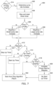
- FIG. 7 depicts a schematic flow diagram of the first flow control protocol 400.
- the first flow control protocol 400 depicted in FIG. 7 may include additional or alternative steps in a similar or different order than what is depicted in FIG. 7 , unless expressly indicated otherwise.
- the first flow control protocol 400 may be utilized to control the pump 104 of the pump/filtration system 100.
- possible pump rate increase values for the pump 104 may be determined 402 based on the previously determined 308, 310 change in filter pressure and/or zone in a manner similar to as discussed above with respect to step 312.
- the controller 152 may be configured to determine 402 that it is to adjust the pump rate of the pump 104 with either a small pump rate increase 410 of 0.01 ml/min or a large pump rate increase 408 of 0.01 ml/min. If the pump rate increase values for the pump have already been determined (e.g., at step 312 of the flow control process 300), determining 402 the pump rate increases as part of the first flow control protocol 400 may be omitted, but this is not required.
- the controller 152 may include a down timer and as part of the first flow control protocol 400, the down timer may be stopped and reset 404 if it has been running.
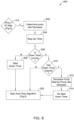
- the down timer of the controller 152 may track an amount of time that the filter pressure of the pump/filtration system 100 has reached or gone beyond the first filter pressure threshold (e.g., an amount of continuous or consecutive time the controller 152 has been controlling operation of the pump/filtration system 100 according to the second flow control protocol 500 without controlling operation of the pump/filtration system 100 according to the first flow control protocol 400).
- the down timer may be a countdown timer, where the timer may be configured to count down from a predetermined time.
- the down timer may be configured to count down from thirty (30) seconds, one (1) minute, two (2) minutes, three (3) minutes, five (5) minutes, 10 (ten) minutes or other suitable amount of time.
- the down timer may not be a countdown timer and may start timing from a time of zero (0) units of time. Such a timer may expire, if at all, after a predetermined set of time.
- the down timer may be utilized to prevent decreasing the pumping rate faster than desired.
- neoformans neoformans
- associated antigens associated antigens
- inflammatory agents a single pass of CSF through a 5kDa TFF and/or a 100kDa TFF may be sufficient to exclude C. neoformans or other reduce the CFUs of C. neoformans in the CSF.
- a 5kDa TFF and/or a 100kDa TFF may be sufficient to exclude or otherwise reduce C. neoformans antigen from the CSF.
- a 5kDa and/or 100kDa TFF may also exclude a number of neuroinflammatory agents such as IL-1ra, IL-6, TNF, CRP, and/or CXCL 10/IP-10 from the CSF.
- U.S. Patent Application Pub. No. US 2016/0051801 is incorporated herein by reference.
- U.S. Patent No. 8,435,204 is incorporated herein by reference.
- U.S. Patent Application No. 62/568,412 (Attorney docket number 1421.1010100) is incorporated herein by reference.
- U.S. Patent Application No. 62/598,846 (Attorney docket number 1421.1011100) is incorporated herein by reference.
Landscapes
- Health & Medical Sciences (AREA)
- Heart & Thoracic Surgery (AREA)
- Engineering & Computer Science (AREA)
- Biomedical Technology (AREA)
- Public Health (AREA)
- Anesthesiology (AREA)
- Hematology (AREA)
- Life Sciences & Earth Sciences (AREA)
- Animal Behavior & Ethology (AREA)
- General Health & Medical Sciences (AREA)
- Veterinary Medicine (AREA)
- Vascular Medicine (AREA)
- Otolaryngology (AREA)
- Ophthalmology & Optometry (AREA)
- Neurology (AREA)
- External Artificial Organs (AREA)
Applications Claiming Priority (3)
| Application Number | Priority Date | Filing Date | Title |
|---|---|---|---|
| US201862693225P | 2018-07-02 | 2018-07-02 | |
| PCT/US2019/040285 WO2020010074A1 (fr) | 2018-07-02 | 2019-07-02 | Systèmes, cathéters et méthodes de traitement le long du système nerveux central |
| EP19745401.0A EP3817801B1 (fr) | 2018-07-02 | 2019-07-02 | Systèmes, cathéters et méthodes de traitement le long du système nerveux central |
Related Parent Applications (1)
| Application Number | Title | Priority Date | Filing Date |
|---|---|---|---|
| EP19745401.0A Division EP3817801B1 (fr) | 2018-07-02 | 2019-07-02 | Systèmes, cathéters et méthodes de traitement le long du système nerveux central |
Publications (2)
| Publication Number | Publication Date |
|---|---|
| EP4582113A2 true EP4582113A2 (fr) | 2025-07-09 |
| EP4582113A3 EP4582113A3 (fr) | 2025-10-08 |
Family
ID=67441643
Family Applications (2)
| Application Number | Title | Priority Date | Filing Date |
|---|---|---|---|
| EP25177734.8A Pending EP4582113A3 (fr) | 2018-07-02 | 2019-07-02 | Systèmes, cathéters et procédés de traitement le long du système nerveux central |
| EP19745401.0A Active EP3817801B1 (fr) | 2018-07-02 | 2019-07-02 | Systèmes, cathéters et méthodes de traitement le long du système nerveux central |
Family Applications After (1)
| Application Number | Title | Priority Date | Filing Date |
|---|---|---|---|
| EP19745401.0A Active EP3817801B1 (fr) | 2018-07-02 | 2019-07-02 | Systèmes, cathéters et méthodes de traitement le long du système nerveux central |
Country Status (8)
| Country | Link |
|---|---|
| US (2) | US11992637B2 (fr) |
| EP (2) | EP4582113A3 (fr) |
| JP (2) | JP7101859B2 (fr) |
| CN (1) | CN112654387B (fr) |
| AU (2) | AU2019298242B2 (fr) |
| CA (1) | CA3105395A1 (fr) |
| ES (1) | ES3038296T3 (fr) |
| WO (1) | WO2020010074A1 (fr) |
Families Citing this family (12)
| Publication number | Priority date | Publication date | Assignee | Title |
|---|---|---|---|---|
| WO2015157334A1 (fr) * | 2014-04-07 | 2015-10-15 | Csf Refresh Llc | Shunt de mesure csf programmable |
| US9901722B2 (en) * | 2014-06-01 | 2018-02-27 | White Swell Medical Ltd | System and method for treatment of pulmonary edema |
| AU2020271894A1 (en) | 2019-04-11 | 2021-12-02 | Enclear Therapies, Inc. | Methods of amelioration of cerebrospinal fluid and devices and systems therefor |
| US12005171B2 (en) | 2020-05-28 | 2024-06-11 | Minnetronix Neuro, Inc. | Filtering systems and filtering manifolds for use with filtering systems |
| US12329930B2 (en) | 2020-09-29 | 2025-06-17 | Enclear Therapies, Inc. | Subarachnoid fluid management method and system |
| CN116471981A (zh) * | 2020-09-29 | 2023-07-21 | 因柯利尔疗法公司 | 蛛网膜下流体管理方法和系统 |
| US11744939B2 (en) | 2020-10-29 | 2023-09-05 | Medtronic, Inc. | Cyclic intrathecal drug delivery system and biomarker monitoring |
| CN115337544B (zh) * | 2021-05-14 | 2025-09-05 | 未来穿戴技术有限公司 | 按摩仪的渗液机制调节方法、装置及按摩仪 |
| AU2022315184A1 (en) * | 2021-07-19 | 2024-03-07 | Enclear Therapies, Inc. | Csf diagnostics platform |
| WO2023183431A1 (fr) * | 2022-03-22 | 2023-09-28 | Enclear Therapies, Inc. | Système et procédé de gestion de cellules cancéreuses dans un csf |
| CN115025376B (zh) * | 2022-04-24 | 2024-01-16 | 中山大学附属第三医院 | 一种脑脊液免疫吸附装置及控制方法 |
| WO2024135626A1 (fr) * | 2022-12-22 | 2024-06-27 | テルモ株式会社 | Dispositif médical |
Citations (2)
| Publication number | Priority date | Publication date | Assignee | Title |
|---|---|---|---|---|
| US8435204B2 (en) | 2006-10-09 | 2013-05-07 | Neurofluidics, Inc. | Cerebrospinal fluid purification system |
| US20160051801A1 (en) | 2014-08-19 | 2016-02-25 | Minnetronix, Inc. | Devices and Systems for Access and Navigation of Cerebrospinal Fluid Space |
Family Cites Families (22)
| Publication number | Priority date | Publication date | Assignee | Title |
|---|---|---|---|---|
| US4904237A (en) * | 1988-05-16 | 1990-02-27 | Janese Woodrow W | Apparatus for the exchange of cerebrospinal fluid and a method of treating brain and spinal cord injuries |
| US6689085B1 (en) * | 1996-07-11 | 2004-02-10 | Eunoe, Inc. | Method and apparatus for treating adult-onset dementia of the Alzheimer's type |
| US7311690B2 (en) * | 2002-02-25 | 2007-12-25 | Novashunt Ag | Implantable fluid management system for the removal of excess fluid |
| JP2004344299A (ja) | 2003-05-21 | 2004-12-09 | Japan Science & Technology Agency | 骨髄自動灌流採取方法およびその装置 |
| US7206715B2 (en) | 2003-12-31 | 2007-04-17 | Cardinal Health 303, Inc. | Empty container detection using container side pressure sensing |
| US6973375B2 (en) * | 2004-02-12 | 2005-12-06 | Mykrolis Corporation | System and method for flow monitoring and control |
| JP4557789B2 (ja) | 2005-05-10 | 2010-10-06 | セイコーエプソン株式会社 | 流体輸送システム、流体の吐出量設定方法 |
| US10478555B2 (en) * | 2006-08-17 | 2019-11-19 | Milan Radojicic | Systems and methods for lumbar cerebrospinal fluid access and treatment |
| US10850235B2 (en) * | 2006-10-09 | 2020-12-01 | Minnetronix, Inc. | Method for filtering cerebrospinal fluid (CSF) including monitoring CSF flow |
| US10695545B2 (en) * | 2006-10-09 | 2020-06-30 | Minnetronix, Inc. | Systems and methods for the conditioning of cerebrospinal fluid |
| US10632237B2 (en) | 2006-10-09 | 2020-04-28 | Minnetronix, Inc. | Tangential flow filter system for the filtration of materials from biologic fluids |
| CN201333213Y (zh) * | 2009-01-06 | 2009-10-28 | 王拥军 | 用于脑脊液净化装置的滤器及管路系统 |
| WO2010123558A1 (fr) * | 2009-04-22 | 2010-10-28 | Neurofluidics, Inc. | Système programmable de conditionnement de liquide cérébrospinal |
| WO2011037838A1 (fr) * | 2009-09-25 | 2011-03-31 | Neuroenterprises, Llc | Dispositif de drainage régulé de fluide cérébrospinal basé sur la gravité |
| US20120302938A1 (en) | 2010-03-19 | 2012-11-29 | University Of Washington | Drainage systems for excess body fluids and associated methods |
| CN102133096B (zh) * | 2011-03-09 | 2012-09-26 | 深圳市德普施科技有限公司 | 一种颅内压监测与脑脊液引流置换治疗仪 |
| US9526834B2 (en) * | 2012-08-30 | 2016-12-27 | Medtronic Minimed, Inc. | Safeguarding measures for a closed-loop insulin infusion system |
| JP6449844B2 (ja) * | 2013-03-14 | 2019-01-09 | インキューブ ラブズ, エルエルシー | 神経学的症状を治療するための脳への薬物の送達のための装置、システムおよび方法 |
| EP3052179B1 (fr) * | 2013-10-01 | 2020-05-06 | École Polytechnique Fédérale De Lausanne (EPFL) | Systèmes de déplacement et de circulation de fluide pour traiter la maladie d'alzheimer |
| CN107106743B (zh) * | 2014-12-30 | 2020-06-05 | 史密夫和内修有限公司 | 用于应用减压治疗的系统和方法 |
| CN108367102B (zh) | 2015-08-05 | 2021-04-30 | 米奈特朗尼克斯有限公司 | 用于来自生物流体的物料的过滤的切向流过滤器系统 |
| CN105396200B (zh) * | 2015-12-08 | 2021-11-05 | 深圳迈瑞科技有限公司 | 输液泵及其输液管路上阻塞报警方法和装置 |
-
2019
- 2019-07-02 JP JP2021500092A patent/JP7101859B2/ja active Active
- 2019-07-02 AU AU2019298242A patent/AU2019298242B2/en active Active
- 2019-07-02 EP EP25177734.8A patent/EP4582113A3/fr active Pending
- 2019-07-02 CA CA3105395A patent/CA3105395A1/fr active Pending
- 2019-07-02 ES ES19745401T patent/ES3038296T3/es active Active
- 2019-07-02 WO PCT/US2019/040285 patent/WO2020010074A1/fr not_active Ceased
- 2019-07-02 CN CN201980057174.2A patent/CN112654387B/zh active Active
- 2019-07-02 EP EP19745401.0A patent/EP3817801B1/fr active Active
- 2019-07-02 US US16/460,090 patent/US11992637B2/en active Active
-
2022
- 2022-07-05 JP JP2022108260A patent/JP7408730B2/ja active Active
- 2022-12-09 AU AU2022283781A patent/AU2022283781B2/en active Active
-
2024
- 2024-04-25 US US18/645,549 patent/US20240293649A1/en active Pending
Patent Citations (2)
| Publication number | Priority date | Publication date | Assignee | Title |
|---|---|---|---|---|
| US8435204B2 (en) | 2006-10-09 | 2013-05-07 | Neurofluidics, Inc. | Cerebrospinal fluid purification system |
| US20160051801A1 (en) | 2014-08-19 | 2016-02-25 | Minnetronix, Inc. | Devices and Systems for Access and Navigation of Cerebrospinal Fluid Space |
Also Published As
| Publication number | Publication date |
|---|---|
| AU2022283781A1 (en) | 2023-02-09 |
| US20200001059A1 (en) | 2020-01-02 |
| EP4582113A3 (fr) | 2025-10-08 |
| JP2021529619A (ja) | 2021-11-04 |
| AU2019298242A1 (en) | 2021-01-28 |
| EP3817801A1 (fr) | 2021-05-12 |
| AU2019298242B2 (en) | 2022-09-15 |
| WO2020010074A1 (fr) | 2020-01-09 |
| CN112654387A (zh) | 2021-04-13 |
| ES3038296T3 (en) | 2025-10-10 |
| CN112654387B (zh) | 2023-08-15 |
| AU2022283781B2 (en) | 2024-02-22 |
| JP2022130700A (ja) | 2022-09-06 |
| US20240293649A1 (en) | 2024-09-05 |
| JP7101859B2 (ja) | 2022-07-15 |
| CA3105395A1 (fr) | 2020-01-09 |
| US11992637B2 (en) | 2024-05-28 |
| JP7408730B2 (ja) | 2024-01-05 |
| EP3817801B1 (fr) | 2025-05-21 |
Similar Documents
| Publication | Publication Date | Title |
|---|---|---|
| AU2022283781B2 (en) | Systems, catheters, and methods for treating along the central nervous system | |
| AU2022271486B2 (en) | Systems, catheters, and methods for treating along the central nervous system | |
| AU2021206834B2 (en) | Systems, catheters, and methods for treating along the central nervous system |
Legal Events
| Date | Code | Title | Description |
|---|---|---|---|
| PUAI | Public reference made under article 153(3) epc to a published international application that has entered the european phase |
Free format text: ORIGINAL CODE: 0009012 |
|
| STAA | Information on the status of an ep patent application or granted ep patent |
Free format text: STATUS: REQUEST FOR EXAMINATION WAS MADE |
|
| 17P | Request for examination filed |
Effective date: 20250520 |
|
| AC | Divisional application: reference to earlier application |
Ref document number: 3817801 Country of ref document: EP Kind code of ref document: P |
|
| AK | Designated contracting states |
Kind code of ref document: A2 Designated state(s): AL AT BE BG CH CY CZ DE DK EE ES FI FR GB GR HR HU IE IS IT LI LT LU LV MC MK MT NL NO PL PT RO RS SE SI SK SM TR |
|
| RAP3 | Party data changed (applicant data changed or rights of an application transferred) |
Owner name: MINNETRONIX NEURO, INC. |
|
| REG | Reference to a national code |
Ref country code: DE Ref legal event code: R079 Free format text: PREVIOUS MAIN CLASS: A61M0001000000 Ipc: A61M0027000000 |
|
| PUAL | Search report despatched |
Free format text: ORIGINAL CODE: 0009013 |
|
| AK | Designated contracting states |
Kind code of ref document: A3 Designated state(s): AL AT BE BG CH CY CZ DE DK EE ES FI FR GB GR HR HU IE IS IT LI LT LU LV MC MK MT NL NO PL PT RO RS SE SI SK SM TR |
|
| RIC1 | Information provided on ipc code assigned before grant |
Ipc: A61M 27/00 20060101AFI20250904BHEP Ipc: A61M 3/02 20060101ALI20250904BHEP Ipc: A61M 1/00 20060101ALI20250904BHEP |
|
| RAP3 | Party data changed (applicant data changed or rights of an application transferred) |
Owner name: PHARAOH NEURO, INC. |