EP4582157A2 - Chaussure électronique de sécurité pour casino - Google Patents
Chaussure électronique de sécurité pour casino Download PDFInfo
- Publication number
- EP4582157A2 EP4582157A2 EP25178804.8A EP25178804A EP4582157A2 EP 4582157 A2 EP4582157 A2 EP 4582157A2 EP 25178804 A EP25178804 A EP 25178804A EP 4582157 A2 EP4582157 A2 EP 4582157A2
- Authority
- EP
- European Patent Office
- Prior art keywords
- playing card
- card
- playing
- housing portion
- leading
- Prior art date
- Legal status (The legal status is an assumption and is not a legal conclusion. Google has not performed a legal analysis and makes no representation as to the accuracy of the status listed.)
- Pending
Links
Images








Classifications
-
- A—HUMAN NECESSITIES
- A63—SPORTS; GAMES; AMUSEMENTS
- A63F—CARD, BOARD, OR ROULETTE GAMES; INDOOR GAMES USING SMALL MOVING PLAYING BODIES; VIDEO GAMES; GAMES NOT OTHERWISE PROVIDED FOR
- A63F1/00—Card games
- A63F1/06—Card game appurtenances
- A63F1/14—Card dealers
-
- A—HUMAN NECESSITIES
- A63—SPORTS; GAMES; AMUSEMENTS
- A63F—CARD, BOARD, OR ROULETTE GAMES; INDOOR GAMES USING SMALL MOVING PLAYING BODIES; VIDEO GAMES; GAMES NOT OTHERWISE PROVIDED FOR
- A63F1/00—Card games
- A63F1/06—Card game appurtenances
-
- A—HUMAN NECESSITIES
- A63—SPORTS; GAMES; AMUSEMENTS
- A63F—CARD, BOARD, OR ROULETTE GAMES; INDOOR GAMES USING SMALL MOVING PLAYING BODIES; VIDEO GAMES; GAMES NOT OTHERWISE PROVIDED FOR
- A63F1/00—Card games
- A63F1/04—Card games combined with other games
-
- A—HUMAN NECESSITIES
- A63—SPORTS; GAMES; AMUSEMENTS
- A63F—CARD, BOARD, OR ROULETTE GAMES; INDOOR GAMES USING SMALL MOVING PLAYING BODIES; VIDEO GAMES; GAMES NOT OTHERWISE PROVIDED FOR
- A63F1/00—Card games
- A63F2001/001—Bridge or baccarat
-
- A—HUMAN NECESSITIES
- A63—SPORTS; GAMES; AMUSEMENTS
- A63F—CARD, BOARD, OR ROULETTE GAMES; INDOOR GAMES USING SMALL MOVING PLAYING BODIES; VIDEO GAMES; GAMES NOT OTHERWISE PROVIDED FOR
- A63F1/00—Card games
- A63F2001/003—Blackjack; Twenty one
-
- A—HUMAN NECESSITIES
- A63—SPORTS; GAMES; AMUSEMENTS
- A63F—CARD, BOARD, OR ROULETTE GAMES; INDOOR GAMES USING SMALL MOVING PLAYING BODIES; VIDEO GAMES; GAMES NOT OTHERWISE PROVIDED FOR
- A63F2250/00—Miscellaneous game characteristics
- A63F2250/58—Antifraud or preventing misuse
Definitions
- the playing cards to be loaded into the shoe are pre-shuffled and packaged.
- it is necessary to open the package take out several (for example, eight decks of) shuffled playing cards, and houses them in the shoe.
- a security electronic shoe for a casino is a security electronic shoe for a casino configured to house a plurality of playing cards to be drawn one by one for a game, comprising: a housing portion configured to house a stacked plurality of playing cards; an opening portion configured to expose a leading playing card among the plurality of playing cards housed in the housing portion; a draw guide portion configured to guide draw of the leading playing card from the opening portion; and a weight configured to push a last playing card of the plurality of playing cards toward the opening portion, wherein a bottom portion of the housing portion slopes so as to descend toward the opening portion, the weight is configured to be movable on the bottom portion of the housing portion toward the opening portion in a state pushing the last playing card toward the opening portion, according to that the last playing card moves toward the opening portion, accompanying that the leading playing card is drawn in sequence, and the housing portion has a structure in which an upper surface and at least one side surface are opened, and the plurality of playing cards can be loaded into the housing portion through the opened
- the housing portion may include a stopper at a position of the plurality of playing cards corresponding to a lower portion of the opened side surface, the stopper configured to restrict a lateral movement of the plurality of playing cards.
- the plurality of playing cards may be to be housed in the housing portion such that back surfaces thereof face the opening portion, and the weight may be configured to contact with a front surface of the last playing card such that the front surface of the last playing card cannot be seen.
- the above security electronic shoe for the casino may further comprise a side cover configured to be movable between a cover position where the side cover covers the opened side surface of the housing portion and an open position where the side cover opens the opened side surface of the housing portion.
- the side cover may be capable of performing a rotating movement between the cover position and the open position.
- the side cover may be capable of performing a parallel movement between the cover position and the open position.
- the above security electronic shoe for the casino may further comprise a side cover configured to be movable between a cover position where the side cover covers the opened side surface of the housing portion and an open position where the side cover opens the opened side surface of the housing portion, and a surface of the side cover opposed to the side surface may be positioned more outside than a surface of the stopper opposed to the side surface when the side cover is in the cover position.
- the side surface may be a side surface on a right side facing in a direction of the draw.
- the draw guide portion may be configured to be removable.
- an electronic shoe configured to house a plurality of playing cards to be drawn one by one by a dealer for a game at a gaming table of a casino (hereinafter simply referred to as "electronic shoe") is described.
- This electronic shoe is used at the gaming table in the casino.
- the game may be, for example, baccarat, blackjack, and so on, but, in the present embodiments, the electronic shoe used for baccarat is described.
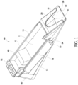
- FIG. 1 is a perspective view showing an electronic shoe according to a first embodiment
- FIG. 2 is a side view showing the electronic shoe according to the first embodiment
- FIG. 3 is a plan view showing the electronic shoe according to the first embodiment
- FIG. 4 is a front view showing the electronic shoe according to the first embodiment.
- the electronic shoe 100 has a rectangular shape as a whole.
- the electronic shoe 100 houses a plurality of playing cards such that the short side thereof are parallel to the long sides of the playing cards.
- the playing cards are removed to the outside of the electronic shoe 100 one by one by a draw operation by a dealer from the front end of the electronic shoe 100.
- the electronic shoe 100 includes a housing portion 10, an opening portion 20, a draw guide portion 30, a weight 40, and a main body 50.
- the lower half part and rear part of the electronic shoe 100 form the main body 50.
- the housing portion 10 is formed so as to extend forward contiguously from the rear end part of the main body 50.
- the housing portion 10 houses a stacked plurality of playing cards. As described above, the stacked plurality of playing cards is housed in the housing portion 10 in the lateral orientation. The long sides of the playing cards are supported on the bottom surface 11 of the housing portion 10. The playing cards are housed in the housing portion 10 such that the back surfaces of the playing cards face forward.
- the part whose height is low of the side wall 14 forms a side surface opened portion of the left side surface, and an upper surface opened portion is formed to be contiguous to the side surface opened portion and opens the housing portion 10 upward.
- the plurality of playing cards can be loaded into the housing portion 10 through the side surface opened portion and the upper surface opened portion.
- the side wall 14 whose height is low is formed at a position of the plurality of playing cards corresponding to the lower portion of the side surface opened portion, and functions as a stopper to restrict a lateral movement of the housed plurality of playing cards.
- the housing portion 10 is provided with the side surface cover 13 including an axis on the outside of the side wall 14 formed to be low.
- the side surface cover 13 rotates around this axis to perform a rotating movement between a cover position and an open position.
- the side surface cover 13 In the cover position, the side surface cover 13 is in an attitude to be upright, and closes the side surface opened portion to cover the housed playing cards.
- the side surface cover 13 In the open position, the side surface cover 13 is in an attitude to be rotated further from the horizontal attitude to open the side surface opened portion.
- the opening portion 20 exposes to the outside the leading playing card among the plurality of playing cards housed in the housing portion 10.
- the opening portion 20 is shaped to be an arch-shape and exposes the center portion of a back surface of the playing card. The dealer can draw out the leading playing card onto the gaming table with its back surface facing up by sliding it while pressing downward on its exposed portion.
- a blind 21 is formed in the opening portion 20 so as to cover over the back surface of the leading playing card exposed therethrough.
- the blind 21 is made of a large number of flexible thin line-shaped members, and divided into the left and right at the center.
- the line-shaped members are provided so as to slope in a drawing direction from the left and right to the center and from the base to the tip. The dealer can apply force to the playing card around a break of the left and right of the line-shaped members to draw out it.
- FIG. 6 is a view showing a structure of the weight according to the first embodiment of the present invention.
- the weight 40 is used for pushing the last playing card among the plurality of playing cards toward the opening portion 20.
- the weight 40 includes a roller 41 including a lateral axis. The lower end portion of the roller 41 protrudes slightly from the bottom of the weight 40. Thereby, the weight 40 is movable in the forward and rearward direction by rotating the roller 41.
- the weight 40 is movable forward and rearward on the bottom surface 11 of the housing portion 10. As described above, the housing portion 10 slopes toward the opening portion 20, and so the weight 40 moves to the opening portion 20 by its own weight. When the plurality of playing cards is loaded in the housing portion 10, the slope surface 42 of the weight 40 pushes the last playing card toward the opening portion 20. Thus, due to the action of the weight 40, the leading playing card is always pushed from the rear side toward the opening portion 20 and exposed through the opening portion 20.
- the weight 40 can be fixed in the rear position of the housing portion 10 by magnets or an engaging mechanism. As shown in FIG. 5 , when loading the playing cards into the housing portion 10, the weight 40 is fixed in this fixed position to form a space in which a new plurality of playing cards can be housed in the housing portion 10. Furthermore, it may be that a sensor detects that the plurality of playing cards is housed in the housing portion 10, and the fixation of the weight 40 by the magnets or the engaging mechanism is automatically released based on this detection of the sensor. When the fixation is released, the weight 40 moves toward the opening portion 20 on the bottom surface 11 of the housing portion 10 by its own weight, contacts the last playing card and pushes the loaded plurality of playing cards toward the opening portion 20 from the last thereof. It may be to detect that the playing cards are housed in the housing portion 10 by detecting that the side surface cover 13 closes the side surface opened portion, or that the upper surface cover 15 described below closes the upper surface opened portion, for example.
- the side surface opened portion and the side surface cover 13, and the result indicating button 53 are all provided on the side facing the dealer when the electronic shoe 100 is placed on the gaming table. That is, the electronic shoe 100 is placed on the left side of the dealer, and so the side surface opened portion and the result indicating button 53 are provided on the left side facing the dealer. Thereby, it become easy for the dealer to operate the result indicating button 53 of the electronic shoe 100 placed on the gaming table and to load the new playing cards into the housing portion 10 through the side surface opened portion.
- the result indicating display 55 is also provided on the left side facing the dealer. Thereby, it is possible to show a game result to the dealer without being seen by a player.
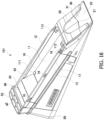
- FIG. 7 is a perspective view showing the electronic shoe according to the first embodiment of the present invention
- FIG. 8 is a side view showing the electronic shoe according to the first embodiment of the present invention
- FIG. 9 is a plan view showing the electronic shoe according to the first embodiment of the present invention.
- the side surface cover 13 closes the side surface opened portion
- the upper surface cover 15 is installed at the housing portion 10 to close the upper surface opened portion.
- the upper surface cover 15 slides from the front to the rear on the slide rail to move to the cover position shown in FIG. 7 .
- the upper surface cover 15 is installed, by which the side surface cover 13 is also fixed in the cover position.
- the electronic shoe 100 may further be provided with sensors (not shown) configured to detect that the side surface cover 13 and the upper surface cover 15 are respectively in the cover position. As those sensors, magnetics or optical sensors may be used. A control device of the electronic shoe 100 outputs an error signal in a case where the sensors do not detect that the side surface cover 13 and upper surface cover 15 are in the cover positions.
- the electronic shoe 100 activates a draw restricting pin 38 (described below) to prohibit the draw of the playing cards in the case where the sensors detect that the side surface cover 13 and upper surface cover 15 are not in the cover position.
- FIG. 11 is a view showing the detail of the draw guide portion according to the first embodiment of the present invention.
- the internal structure of the restricting portion 31 is shown in a state where a portion of the restricting portion 31 is removed.
- the inside of the restricting portion 31 is provided with code reading sensors 33 and 34 for reading a code representing at least a number (rank) of the shuffled playing card, and card detecting sensors 35 and 36 for detecting that the playing card C is drawn out.
- the restricting portion 31 of the draw guide portion 30 may be removable, and the draw guide portion 30 may also be removable from the opening portion 20. Whereby, various types of maintenance become possible.
- Each of the code reading sensors 33 and 34 includes a lamp configured to irradiate UV light and a sensor configured to read the mark.
- the marks M1 and M2 representing the code information are formed in two steps at the end on the side of the short side of the card. As the code information, the two rows of marks M1 and M2 are printed over a plurality of columns. The code information is expressed by combination of presence and absence of the marks M1 and M2.
- the code reading sensor 33 reads the mark M1 and the code reading sensor 34 reads the mark M2.
- the electronic shoe 100 reads the code information based on the combination of the read marks M1 and M2.
- the code reading sensors 33 and 34 obtain the code information by reading in sequence in the draw direction the marks M1 and M2 of the playing card being drawn out.
- the code information represents the rank of the playing card C. Therefore, the electronic shoe 100 can determine the rank of the playing card C being drawn out.
- the electronic shoe 100 determines a game result based on the determined ranks of the cards.
- the game result may be a player win, banker win, or tie.
- the game result indicating button 53 is pressed, the corresponding lamp of the result indicating lamps 52 is turned on according to the determined game result.
- the draw guide portion 30 is further provided with a restricting bar 37 configured to prevent the two playing cards from being drawn simultaneously.
- the restricting bar 37 is formed as a metal part.
- the restricting bars 37 are provided on both sides of the draw guide portion 30.
- FIG. 13 is a view showing an action of the restricting bar according to the first embodiment of the present invention.
- a gap through which only one playing card can pass is formed between the restricting bar 37 and the slope portion 32.
- the restricting bar 37 acts so as to press from the upper side the playing card C being drawn while sliding down the slope portion 32.
- the side surface cover 13 has the structure in which it can perform the rotating movement between the cover position and the open position, but the side surface cover 13 may has a structure in which it can perform a parallel movement between the cover position and the open position. Moreover, the side surface cover 13 may be installable in the cover position and also removable from the cover position.
- the backflow of the leading playing card is restricted by the backflow stopper 112, and so it is impossible to contact and draw out the second playing card, and it is prevented that the illicitness that the playing card is drawn in a different order from the original order.
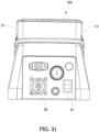
- FIGs. 25-31 are a perspective view, a plan view, a right side view, a left side view, a front view, a bottom view, and a rear view showing the electronic shoe according to the third embodiment of the present invention.
- FIG. 32 is a perspective view showing the electronic shoe in a state in which an upper surface cover is removed according to the third embodiment of the present invention.
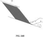
- the corners are removed, and those are shaped to be rounded. Whereby, it is easier that an open-hand operation that a dealer draws a playing card C from the electronic shoe 102 and simultaneously turns over the playing card C to face the front side up.
- the electronic shoe 102 in the present embodiment includes magnets respectively built into the rear end of an upper surface cover 15 and the rear end portion of the housing portion 10 which contacts the rear end of the upper surface cover 15 when the upper surface cover 15 is installed. Whereby, a position of the upper surface cover 15 is held by magnetic force of the magnets in a state in which it is installed in the electronic shoe 102.
- the upper surface cover 15 can be easily removed by sliding the upper surface cover 15 against the magnetic force of the magnets.
- a protrusion 157 extending in the forward and reward direction is formed on the outside of the side surface of the upper surface cover 15. Whereby, it is facilitated to hang the finger on this protrusion 157 to lift the electronic shoe 102 in a state in which the upper surface cover 15 is installed.
- the back surface of the electronic shoe 102 includes a connector 62 for connecting with an external device and a power switch 61 of the electronic shoe 102.
- chamfering is performed to outer portions 132 of the upper ends of the front and rear ends of the side surface cover 13 and portions 141 of a side wall 14 opposite to the outer portions 132 of the side surface cover 13. Whereby, it is prevented that the inner side surface of the upper surface cover 15 is caught by a step at a boundary between the upper end of this side surface cover 13 and the side wall 14 to hinder a smooth sliding in a process in which the upper surface cover 15 slides to the closed position.
- FIG. 33 is a view showing an indicating example of a result indicating display according to the third embodiment of the present invention.
- the result indicating display 55 according to the present embodiment indicates information in two rows. Specifically, in the result indicating display 55, as a game result, ranks and suits of two playing cards C which is banker hand are indicated in the upper row on the left side and a number of an units digit of a total value of ranks of two playing cards C which is banker hand is indicated in the lower row, and ranks and suits of two playing cards C which is player hand are indicated in the upper row on the right side and a number of an units digit of a total value of ranks of two playing cards C which is player hand is indicated in the lower row.
- the electronic shoe 102 is provided with, as a result indicating lamp 54, a lamp for indicating banker 6 as well as lamps for indicating the respective results of player win, banker win, and tie.
- Banker 6 means that a hand of banker wins by 6. In this case, even when betting on the banker win, an amount of chips to be paid out is a half amount of a bet amount.
- a bet area is provided with a bet area for betting on that the banker wins by 6 (called “super 6", “lucky 6", and so on)
- payment is performed for chips bet thereon at a multiplier greater than 1 time (for example, 24 times).
- the electronic shoe 102 is provided with a lamp for indicating that the banker 6 occurs as one of the result indicating lamps 54.
- FIG. 34 is a view showing a detail of the draw guide portion according to the third embodiment of the present invention.
- an inside structure of a restricting portion 31 is shown in a state in which the restricting portion 31 is removed.
- Each of the front end portions of the side walls 12 and 14 includes a restraining portion 18 for restraining lifting of housed playing cards C.
- the lower surface of this restraining portion 18 has a curved shape convex downward.
- the playing card C does not hinder when removing the restricting portion 31 as is shown in FIG. 34 and maintaining the restricting bar 37. That is, for the height of the restricting bar 37, a precise adjustment is necessary in order to prevent two cards draw. Therefore, the adjustment may be necessary in a process of using the electronic shoe 102, and, even in such case, the leading playing card C does not contact with the restricting bar 37, and so it is possible to adjust the restricting bar 37 without removing the playing cards C from the housing portion 10.
- the electronic shoe 102 is provided with a sensor cover 39 covering code reading sensors 33 and 34 and card detecting sensors 35 and 36.
- the periphery portion of the sensor cover 39 is provided with a packing in order to prevent paper dust of the playing card C from entering the interior.
- the sensor cover 39 is formed of transparent material.
- a sponge-like dustproof member or seal member surrounds the peripheries of sensor chips on a sensor substrate.
- FIG. 36 is a perspective view showing the upper surface cover according to the third embodiment of the present invention.
- a plurality of ribs 152 is formed on the inner surface 151 of the upper surface cover 15.
- guides 155 extending in the longitudinal direction is formed at positions close to the left and right side walls 156 on the inner surface 151.
- the upper ends of the side walls 12, 14 and side surface cover 13 fit into and fixed in the gaps between the guides 155 formed on the inner surface 151 of the upper surface cover 15 and the side wall 156. Therefore, in the state in which the upper surface cover 15 is installed, the side walls 12, 14 and side surface cover 13 and the upper surface cover 15 are firmly fixed, and, together with the action of the metal reinforcing plate described above, it is possible to reduce deformation when the electronic shoe 102 is lifted.
- baccarat game in which the electronic shoe 102 is used, there are a type of a game operation called squeeze baccarat in which a player is permitted to open a playing card C drawn from the electronic shoe 102, and a type of a game operation called open hand baccarat in which the dealer oneself opens a playing card C drawn from the electronic shoe 102.
- squeeze baccarat a type of a game operation
- open hand baccarat in which the dealer oneself opens a playing card C drawn from the electronic shoe 102.
- the dealer opens the playing card C drawn from the electronic shoe 102.
- the open hand baccarat the dealer draws a playing card C from the electronic shoe 102 and simultaneously opens the playing card C and places it on the gaming table.
- FIG. 37 is a perspective view showing the electronic shoe according to the third embodiment of the present invention.
- the bottom surface of the electronic shoe 102 is installed with bottom raising parts 71 and 72 raising the bottom surface of the electronic shoe 102.
- the height of the upper surface of the draw guide portion 30 on which the playing card C to be drawn slides from a table surface of the gaming table become higher, and so it become easier for the dealer to pick up the drawn card.
- an observation window may be provided on the upper surface cover 15.
- This observation window may be provided at the upper portion of the upper surface cover 15 and it may be possible to observe the weight 40 held at the upper end portion of the housing portion 10. Whereby, when the upper surface cover 15 is installed to the electronic shoe 102 and the weight 40 slides downward, the user cannot observe the weight 40 through the observation window, and so check that the weight 40 slid downward.
- a sensor configured to detect that the weight 40 slid from a holding position.
- it may be to provide a sensor formed of an LED light and a photodiode sensor at a position corresponding to the weight 40 and detect presence or absence of the weight 40 in the holding position.
- a computer is built in the main body 50 of the electronic shoe 102 according to the present embodiment.
- This computer includes an arithmetic processor, memory, and storage device, and, as a processing portion of the electronic shoe 102, activates by a program according to the present embodiment and performs the following information processing.
- the processing portion stores information on ranks of drawn cards and game results as log information in the storage device together with information on a date and time of the game.
- the processing portion detects that the upper surface cover 15 is opened or closed as well as when some error occurs, it stores those events as the log information in the storage device together with the information of the date and time.
- analyzing software configured to analyze this log information may be ran.
- This analyzing software may, for example, perform statistical processing on the game results or on the ranks of the drawn playing cards C.
- the playing card C is set at a position where the mark M1 is read by the code reading sensor 33, a reading value of the code reading sensor 33 is obtained, and the threshold value of the code reading sensor 33 is set based on this.
- the playing card C is set at a position where the mark M2 is read by the code reading sensor 34, a reading value of the code reading sensor 34 is obtained, and the threshold value of the code reading sensor 34 is set based on this.
- the processor may alternatively obtain a change in a reading value of the code reading sensors 33 and 34 (values of areas in which the marks M1 and M2 are present and absent) while drawing the playing card C, and set the threshold value based on this reading value.
Landscapes
- Engineering & Computer Science (AREA)
- Multimedia (AREA)
- Purses, Travelling Bags, Baskets, Or Suitcases (AREA)
- Physics & Mathematics (AREA)
- General Physics & Mathematics (AREA)
- Control Of Vending Devices And Auxiliary Devices For Vending Devices (AREA)
- Casings For Electric Apparatus (AREA)
Applications Claiming Priority (4)
| Application Number | Priority Date | Filing Date | Title |
|---|---|---|---|
| JP2022110486 | 2022-07-08 | ||
| JP2022132265 | 2022-08-23 | ||
| JP2023086884 | 2023-05-26 | ||
| EP23183414.4A EP4302845B1 (fr) | 2022-07-08 | 2023-07-04 | Sabot électronique de sécurité pour casino |
Related Parent Applications (2)
| Application Number | Title | Priority Date | Filing Date |
|---|---|---|---|
| EP23183414.4A Division EP4302845B1 (fr) | 2022-07-08 | 2023-07-04 | Sabot électronique de sécurité pour casino |
| EP23183414.4A Division-Into EP4302845B1 (fr) | 2022-07-08 | 2023-07-04 | Sabot électronique de sécurité pour casino |
Publications (2)
| Publication Number | Publication Date |
|---|---|
| EP4582157A2 true EP4582157A2 (fr) | 2025-07-09 |
| EP4582157A3 EP4582157A3 (fr) | 2025-10-29 |
Family
ID=87136174
Family Applications (4)
| Application Number | Title | Priority Date | Filing Date |
|---|---|---|---|
| EP23183414.4A Active EP4302845B1 (fr) | 2022-07-08 | 2023-07-04 | Sabot électronique de sécurité pour casino |
| EP25178804.8A Pending EP4582157A3 (fr) | 2022-07-08 | 2023-07-04 | Chaussure électronique de sécurité pour casino |
| EP25178791.7A Pending EP4582156A3 (fr) | 2022-07-08 | 2023-07-04 | Chaussure électronique de sécurité pour casino |
| EP23835586.1A Pending EP4552711A1 (fr) | 2022-07-08 | 2023-07-06 | Sabot électronique de sécurité pour casino |
Family Applications Before (1)
| Application Number | Title | Priority Date | Filing Date |
|---|---|---|---|
| EP23183414.4A Active EP4302845B1 (fr) | 2022-07-08 | 2023-07-04 | Sabot électronique de sécurité pour casino |
Family Applications After (2)
| Application Number | Title | Priority Date | Filing Date |
|---|---|---|---|
| EP25178791.7A Pending EP4582156A3 (fr) | 2022-07-08 | 2023-07-04 | Chaussure électronique de sécurité pour casino |
| EP23835586.1A Pending EP4552711A1 (fr) | 2022-07-08 | 2023-07-06 | Sabot électronique de sécurité pour casino |
Country Status (10)
| Country | Link |
|---|---|
| US (4) | US20250213959A1 (fr) |
| EP (4) | EP4302845B1 (fr) |
| JP (3) | JPWO2024010055A1 (fr) |
| KR (4) | KR20250025022A (fr) |
| CN (5) | CN121513436A (fr) |
| AU (4) | AU2023303282A1 (fr) |
| CA (1) | CA3205843A1 (fr) |
| ES (1) | ES3038737T3 (fr) |
| PH (1) | PH12023050341A1 (fr) |
| WO (1) | WO2024010055A1 (fr) |
Families Citing this family (1)
| Publication number | Priority date | Publication date | Assignee | Title |
|---|---|---|---|---|
| KR20250112612A (ko) | 2024-01-17 | 2025-07-24 | 주식회사 엘지에너지솔루션 | 배터리 팩 및 이를 포함하는 자동차 |
Family Cites Families (26)
| Publication number | Priority date | Publication date | Assignee | Title |
|---|---|---|---|---|
| DE4439502C1 (de) * | 1994-11-08 | 1995-09-14 | Michail Order | Spielanlage zur professionellen Ausübung von Tischspielen mit Spielkarten und Jetons, insbesondere des Spieles "Black Jack" |
| US6582301B2 (en) * | 1995-10-17 | 2003-06-24 | Smart Shoes, Inc. | System including card game dispensing shoe with barrier and scanner, and enhanced card gaming table, enabling waging by remote bettors |
| CA2306226A1 (fr) * | 1997-10-14 | 1999-04-22 | Shane Long | Procede de manipulation de cartes dans un sabot de distribution et sabot de distribution |
| TW517215B (en) * | 2001-04-24 | 2003-01-11 | Asahi Seiko Co Ltd | An automatic card dispensing unit with display capability |
| JP2005198668A (ja) * | 2002-01-21 | 2005-07-28 | Matsui Gaming Machine:Kk | カードシャッフル装置 |
| US9539495B2 (en) * | 2008-08-15 | 2017-01-10 | Bally Gaming, Inc. | Intelligent automatic shoe and cartridge |
| US20070216092A1 (en) * | 2006-03-15 | 2007-09-20 | Bally Gaming, Inc. | Card shoe for holding playing cards |
| US8636285B2 (en) * | 2006-05-03 | 2014-01-28 | Shfl Entertainment, Inc. | Ergonomic card delivery shoe |
| US20090121429A1 (en) * | 2007-11-09 | 2009-05-14 | Shuffle Master, Inc. | Card delivery shoe and methods of fabricating the card delivery shoe |
| PH12013502318A1 (en) * | 2011-06-03 | 2019-03-22 | The United States Playing Card Company | Device to secure the mouth of a playing card shoe |
| JP2015128458A (ja) * | 2012-04-23 | 2015-07-16 | エンゼルプレイングカード株式会社 | カード読み取り装置及びテーブルゲームシステム |
| US9452348B2 (en) * | 2012-08-09 | 2016-09-27 | Deq Systems Corp. | Card dealing shoe |
| CA2886006A1 (fr) * | 2012-08-09 | 2014-02-13 | Dp Stud, Inc. D/B/A Deq Systems Corp. | Sabot de distribution de cartes |
| JP6030412B2 (ja) * | 2012-10-23 | 2016-11-24 | エンゼルプレイングカード株式会社 | テーブルゲームシステム |
| NZ726266A (en) * | 2014-05-15 | 2018-04-27 | Angel Playing Cards Co Ltd | Card shooter device and card storage method |
| WO2016049619A1 (fr) * | 2014-09-26 | 2016-03-31 | The United States Playing Card Company | Sabot de distribution de cartes à jouer |
| KR20170046264A (ko) * | 2015-10-21 | 2017-05-02 | 이정우 | 모바일에 의한 카드 매수 사기 방지 카드 슈 |
| US9770647B1 (en) | 2016-03-14 | 2017-09-26 | Tien-Shu Hsu | Dealing shoe structure |
| JP6434478B2 (ja) | 2016-12-13 | 2018-12-05 | エンゼルプレイングカード株式会社 | カード収容部からカードを引出す方法およびテーブルゲームシステム |
| CN206511285U (zh) * | 2016-12-30 | 2017-09-22 | 浙江维融电子科技股份有限公司 | 一种方便取放薄片介质的箱体结构 |
| AU2019203350B2 (en) * | 2018-05-14 | 2021-04-29 | Angel Group Co., Ltd. | Table game management system and game management system |
| JP7272804B2 (ja) | 2019-01-24 | 2023-05-12 | 株式会社 Mtg | 電気刺激装置 |
| JP2019188173A (ja) * | 2019-06-13 | 2019-10-31 | エンゼルプレイングカード株式会社 | テーブルゲームシステム |
| JP7620869B2 (ja) | 2021-01-18 | 2025-01-24 | 大日本印刷株式会社 | 容器及びその予備成形体 |
| JP7671490B2 (ja) | 2021-02-28 | 2025-05-02 | 株式会社イーアールアイ | 移動体管理システム及び移動局 |
| EP4541434A3 (fr) * | 2022-01-12 | 2025-06-25 | Evolution Malta Limited | Chaussure de carte |
-
2023
- 2023-07-04 EP EP23183414.4A patent/EP4302845B1/fr active Active
- 2023-07-04 EP EP25178804.8A patent/EP4582157A3/fr active Pending
- 2023-07-04 ES ES23183414T patent/ES3038737T3/es active Active
- 2023-07-04 EP EP25178791.7A patent/EP4582156A3/fr active Pending
- 2023-07-05 CN CN202511777098.6A patent/CN121513436A/zh active Pending
- 2023-07-05 CN CN202510730902.9A patent/CN120661907A/zh active Pending
- 2023-07-05 CN CN202510730900.XA patent/CN120661906A/zh active Pending
- 2023-07-06 KR KR1020257002378A patent/KR20250025022A/ko active Pending
- 2023-07-06 PH PH1/2023/050341A patent/PH12023050341A1/en unknown
- 2023-07-06 CN CN202510095163.0A patent/CN120053952A/zh active Pending
- 2023-07-06 AU AU2023303282A patent/AU2023303282A1/en active Pending
- 2023-07-06 WO PCT/JP2023/025053 patent/WO2024010055A1/fr not_active Ceased
- 2023-07-06 AU AU2023204335A patent/AU2023204335A1/en active Pending
- 2023-07-06 US US18/881,570 patent/US20250213959A1/en active Pending
- 2023-07-06 JP JP2024532627A patent/JPWO2024010055A1/ja active Pending
- 2023-07-06 EP EP23835586.1A patent/EP4552711A1/fr active Pending
- 2023-07-06 KR KR1020230087861A patent/KR20240007617A/ko active Pending
- 2023-07-06 CN CN202380050233.XA patent/CN119816345A/zh active Pending
- 2023-07-06 US US18/218,801 patent/US20240009548A1/en active Pending
- 2023-07-07 CA CA3205843A patent/CA3205843A1/fr active Pending
-
2025
- 2025-05-12 AU AU2025203419A patent/AU2025203419A1/en active Pending
- 2025-05-12 AU AU2025203418A patent/AU2025203418A1/en active Pending
- 2025-05-14 JP JP2025081190A patent/JP7747930B2/ja active Active
- 2025-05-14 JP JP2025081188A patent/JP7747929B2/ja active Active
- 2025-05-20 KR KR1020250065206A patent/KR20250076499A/ko active Pending
- 2025-05-20 KR KR1020250065204A patent/KR20250076498A/ko active Pending
- 2025-05-21 US US19/214,437 patent/US20250281818A1/en active Pending
- 2025-05-21 US US19/214,520 patent/US20250281819A1/en active Pending
Also Published As
Similar Documents
| Publication | Publication Date | Title |
|---|---|---|
| US20250281819A1 (en) | Security electronic shoe for casino | |
| US10130867B2 (en) | Table game system | |
| EP4145381A1 (fr) | Plateau à double puce, plateau à puce et système de gestion de jeu | |
| CN104582802A (zh) | 纸牌发牌装置以及方法 | |
| JP7344255B2 (ja) | テーブルゲームシステム | |
| US11887435B2 (en) | Game system | |
| CN111821680B (zh) | 纸牌发牌装置以及纸牌收纳方法 | |
| HK40105491A (zh) | 娱乐场用安全电子靴 | |
| JP2022009481A (ja) | テーブルゲームシステム | |
| JP2009285500A (ja) | 遊技機 |
Legal Events
| Date | Code | Title | Description |
|---|---|---|---|
| PUAI | Public reference made under article 153(3) epc to a published international application that has entered the european phase |
Free format text: ORIGINAL CODE: 0009012 |
|
| STAA | Information on the status of an ep patent application or granted ep patent |
Free format text: STATUS: REQUEST FOR EXAMINATION WAS MADE |
|
| 17P | Request for examination filed |
Effective date: 20250526 |
|
| AC | Divisional application: reference to earlier application |
Ref document number: 4302845 Country of ref document: EP Kind code of ref document: P |
|
| AK | Designated contracting states |
Kind code of ref document: A2 Designated state(s): AL AT BE BG CH CY CZ DE DK EE ES FI FR GB GR HR HU IE IS IT LI LT LU LV MC ME MK MT NL NO PL PT RO RS SE SI SK SM TR |
|
| PUAL | Search report despatched |
Free format text: ORIGINAL CODE: 0009013 |
|
| AK | Designated contracting states |
Kind code of ref document: A3 Designated state(s): AL AT BE BG CH CY CZ DE DK EE ES FI FR GB GR HR HU IE IS IT LI LT LU LV MC ME MK MT NL NO PL PT RO RS SE SI SK SM TR |
|
| RIC1 | Information provided on ipc code assigned before grant |
Ipc: A63F 1/14 20060101AFI20250924BHEP |