EP4582202A1 - Bohrer, verfahren zur herstellung eines bohrers und verwendung eines solchen bohrers - Google Patents
Bohrer, verfahren zur herstellung eines bohrers und verwendung eines solchen bohrers Download PDFInfo
- Publication number
- EP4582202A1 EP4582202A1 EP24150347.3A EP24150347A EP4582202A1 EP 4582202 A1 EP4582202 A1 EP 4582202A1 EP 24150347 A EP24150347 A EP 24150347A EP 4582202 A1 EP4582202 A1 EP 4582202A1
- Authority
- EP
- European Patent Office
- Prior art keywords
- drill
- marking
- tip
- body portion
- flute
- Prior art date
- Legal status (The legal status is an assumption and is not a legal conclusion. Google has not performed a legal analysis and makes no representation as to the accuracy of the status listed.)
- Pending
Links
Images


Classifications
-
- B—PERFORMING OPERATIONS; TRANSPORTING
- B23—MACHINE TOOLS; METAL-WORKING NOT OTHERWISE PROVIDED FOR
- B23B—TURNING; BORING
- B23B51/00—Tools for drilling machines
-
- B—PERFORMING OPERATIONS; TRANSPORTING
- B23—MACHINE TOOLS; METAL-WORKING NOT OTHERWISE PROVIDED FOR
- B23B—TURNING; BORING
- B23B49/00—Measuring or gauging equipment on boring machines for positioning or guiding the drill; Devices for indicating failure of drills during boring; Centering devices for holes to be bored
- B23B49/001—Devices for detecting or indicating failure of drills
-
- B—PERFORMING OPERATIONS; TRANSPORTING
- B23—MACHINE TOOLS; METAL-WORKING NOT OTHERWISE PROVIDED FOR
- B23B—TURNING; BORING
- B23B2251/00—Details of tools for drilling machines
- B23B2251/52—Depth indicators
-
- B—PERFORMING OPERATIONS; TRANSPORTING
- B23—MACHINE TOOLS; METAL-WORKING NOT OTHERWISE PROVIDED FOR
- B23B—TURNING; BORING
- B23B2260/00—Details of constructional elements
- B23B2260/104—Markings, i.e. symbols or other indicating marks
-
- B—PERFORMING OPERATIONS; TRANSPORTING
- B23—MACHINE TOOLS; METAL-WORKING NOT OTHERWISE PROVIDED FOR
- B23B—TURNING; BORING
- B23B2260/00—Details of constructional elements
- B23B2260/144—Wear indicators
Definitions
- the present invention belongs to the technical field of metal cutting. More specifically the present invention belongs to the field of drilling tools or drills and especially, but not exclusively, solid carbide drills.
- the present invention relates to a drill according to the preamble of claim 1 as well as a method for producing a drill according to the preamble of claim 11.
- the invention relates to a drill comprising a front end comprising a drill tip, a rear end opposite the front end, a rotational axis of the drill extending between the front and rear ends thereof, a shank portion adjacent to the rear end and configured for attachment to a machine tool, a drill body portion extending between the front end and the shank portion, at least one flute extending from the front end along the drill body portion towards the shank portion, and at least one marking at a fixed position along the rotational axis on the drill body portion.
- Such a drill is already known from any of the documents FR 2851945 A1 , DE 19950390 A1 and US 4904130 A , each of which showing a solid carbide drill with markings intended to indicate a depth of the bore during a drilling operation, or drilling depth, by being positioned at specific length intervals to the tip of the drill.
- drills of this type are driven too deep into the workpiece, i.e. deeper than the drill is suitable for, which impairs the drilling performance, for instance due to unsatisfactory chip evacuation, and may even result in damage of the drill and/or workpiece.
- the maximum drilling depth is particularly difficult to keep track of on solid carbide drills, which are usually reconditioned several times during their service life by re-grinding the drill tip, whereby the length of the drill is reduced and thus also the maximum drilling capability.
- Such a marking provides a visual aid to a machine operator regarding how to use the drill in a proper way, i.e. in a way for which the drill is manufactured, so as to maintain maximum drilling performance and minimizing the risk of damage to the drill or workpiece.
- the operator may by means of said marking keep track of, during use of the drill, if a condition for proper use is met or not, and thereby adapt said use to make sure said condition is met and thereby the maximum capability of the drill utilized.
- Such a marking according to the invention could be used as aid to indicate conditions of proper use of many different types, such as a maximum drilling depth or a maximum reconditionable length of the drill tip, as a few examples.
- said position is selected based on the geometry of the drill between the marking and the front end of the drill with respect to at least one characteristic.
- said use parameter is a drilling depth.
- said at least one characteristic is a design of the at least one flute.
- said use parameter is abrasion of the drill tip.
- said at least one characteristic is a design of the drill tip.
- said position of the first marking is selected based on a said characteristic in the form of a design of the at least one flute and that said position of the second marking is selected based on a said characteristic in the form of a design of the drill tip.
- the drill is a solid carbide drill.
- the invention is especially useful by a solid carbide drill which is intended to be reconditioned by re-grinding of the drill tip as the problems the invention aims to solve are are bigger by drills of this type.
- said at least one marking is arranged to give an information that is permanent.
- the invention also relates to a method for producing a drill and use of a drill according to the appended independent claims thereof. Realizations of, and advantages with, such a method and use clearly appears from the above and following description of embodiments of a drill according to the invention.
- a method for producing a drill according to the invention comprises the steps of:
- step a-2) further comprises selecting a said position such as to ensure that a use parameter of a part of the drill reaching from said front end to said position is at a level ensuring that a condition for proper use of the drill is met.
- said use parameter is a drilling depth.
- said use parameter is abrasion of the drill tip.
- the position is selected based on the geometry of the drill between the marking to be applied and the front end of the drill with respect to at least one characteristic.
- said at least one characteristic is a design of the drill tip.
- step b) comprises applying two markings, at fixed positions and at a distance to each other along the rotational axis of the drill, on the drill body portion
- step a-2) comprises selecting a position on the drill body portion for each said marking to be applied such that it enables determination of whether a condition for proper use of the drill is met during a use of the drill.
- a first of said markings has a drilling depth as said use parameter of the drill and a second of said markings has abrasion of the drill tip as said use parameter of the drill.
- said position of the first marking is selected based on a said characteristic in the form of a design of the at least one flute and said position of the second marking is selected based on a said characteristic in the form of a design of the drill tip.
- step a-2) comprises selecting a position for said at least one marking to be applied by evaluating which is smaller of the two values A and B:
- the drill 1 is a solid carbide drill intended to be used in an industrial drilling machine or other machine with drilling function, such as a multi-task CNC machine.
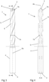
- the drill 1 comprises a front end 2 and an opposite rear end 3.
- the front end comprises a drill tip with cutting edges 8 by means of which the drill is configured to cut into the material of a workpiece, by rotation of the drill around a rotational axis A R extending between the front 2 and rear 3 ends thereof, during a drilling operation for cutting a hole in the workpiece.
- the drill 1 further comprises a first marking 7a arranged at a fixed position along the rotational axis A R , i.e. along a longitudinal extension of the drill, on the drill body portion 5.
- the marking may be applied to the drill body portion by use of laser or by grinding, as a few examples.
- Said first marking 7a is more particularly arranged at a said position enabling determination of whether a condition for proper use of the drill 1 is met during a use of the drill.
- Proper use shall in this regard be interpreted as use in a manner for which the drill 1 is made and intended, while maintaining maximum performance and minimizing the risk of damage to the drill or workpiece.
- a condition for proper use thus states that use of the drill with respect to at least one use parameter should be at a specific value or at a specific side of a given threshold.
- the first marking 7a is arranged at a said position making it possible for an operator of the drilling machine in which the drill 1 is used to, during use of the drill - for instance by performing a drilling operation, determine whether a condition for proper use of the drill is met, that is - whether the drilling depth is on an acceptable level, as is the case if the first marking 7a is visible for the operator, i.e. not driven into and hidden in the workpiece.
- the use parameter "drilling depth” is accordingly at a level ensuring that said condition for proper use of the drill 1 is met at a part of the drill 1 reaching from said front end 2 to said position of the first marking 7a, or the other way around, from the first marking 7a forwardly to the forwardmost end point of the drill.
- the position for the first marking 7a indicating the maximum drilling depth of the drill 1 is determined and selected based on the geometry of the drill between the marking 7a and the front end 2 thereof, with respect to at least one characteristic.
- the main characteristic of the geometry of the drill 1 defining an actual maximum drilling depth allowed before drilling performance deteriorates is the design of the flute or flutes 6 and more specifically the cross-sectional shape or area of each flute defining its ability to evacuate chips from the hole being drilled.
- the position for the first marking 7a could be defined solely based on this characteristic, or by taking one or more further into consideration.
- the determination of the position for the first marking 7a is further described in the below description of a method for producing a drill 1 according to the invention.
- Said second marking 7b is more particularly arranged at a said position enabling determination of whether another condition for proper use of the drill 1 is met during a use of the drill.
- said use parameter is abrasion of the drill tip and the marking hence indicates a limit for maximum reduction of the drill tip - and thereby drill - length during use of the drill 1, by abrasion of material by wear during drilling or by re-grinding the drill tip, i.e. reconditioning of the drill to restore its original performance after a period of wear, before there is a risk that original/intended functionality is impacted.
- the drill is not reduced in length beyond the position of said second marking 7b it is ensured that the drilling performance will be as intended and that no risk for damage of the drill or workpiece is present.
- the second marking 7b is arranged at a said position making it possible for an operator of the drilling machine in which the drill 1 is used to, during use of the drill - for instance by performing a drilling operation or, and especially, by re-grinding the drill tip, determine whether a condition for proper use of the drill is met, that is - whether the abrasion of the drill tip is on an acceptable level, as is the case if the second marking 7b is visible for the operator, i.e. not worn or grinded away.
- the use parameter "abrasion of the drill tip” is accordingly at a level ensuring that said condition for proper use of the drill 1 is met at a part of the drill 1 reaching from the forwardmost point of said front end 2 to said position of the second marking 7b, or the other way around, from the second marking 7b forwardly to the forwardmost point of the drill.
- the position for the second marking 7b indicating the maximum abrasable or reconditionable length of the drill 1 is determined and selected based on the geometry of the drill between the marking 7b and the front end 2 thereof, with respect to at least one characteristic.
- the main characteristic of the geometry of the drill 1 defining an actual maximum abrasable or reconditionable length allowed before drilling performance deteriorates is the design of the drill tip and more specifically the cut diameter of the drill tip defining the diameter of a hole to be drilled, meaning that a reduction of the diameter of the drill tip due to shortening, for instance re-grinding, of the drill would result in that a hole being drilled would be smaller than the nominal diameter indicated by the drill manufacturer.
- the position for the second marking 7b could be defined solely based on this characteristic, or by taking one or more further into consideration, such as body clearance, web clearance or body taper, to mention a few examples.
- the determination of the position for the second marking 7b is further described in the below description of a method for producing a drill 1 according to the invention.
- the position for the second marking 7b is selected based on the geometry of the drill 1 between the second marking to be applied and the front end 2, i.e. the forwardmost end, of the drill with respect to at least one characteristic, in the form of a design of the drill tip.
- steps a-2) and b) it is also possible to first perform the steps a-2) and b) to apply one or more markings on a drill blank, and thereafter process the blank by grinding of flutes 6, cutting edges 8 etc, i.e. the one or more markings may be applied to the drill to be produced before the other features thereof as mentioned in step a).
- the one or more markings 7a-b may be applied by use of laser or by grinding, as a few examples. Furthermore, said markings of a drill according to the invention, or to be applied to a drill in a method of producing a drill according to the invention, do not have to be constituted by lines extending around the peripheral surface of the drill, as shown in the drawings, but each marking may independently be constituted by one or more dots, a shorter line or by the border of a colored area of the drill, to mention a few examples.
- first 7a and second 7b markings may be provided on a drill 1 according to the invention, and such a drill may also be included with other said markings, connected with other conditions for proper use than those mentioned.
- a drill 1 is provided which is provided with markings 7a-b which each in itself and with no further information enables determination of whether a condition for proper use of the drill is met during a use of the drill, and in other words, indicates how the drill should be used within the limits for "proper use” defined by the structure and geometry of the drill.
- a first marking 7a on the outer diameter of the drill indicates the maximum drilling depth the drill can achieve.
- This marking provides a visual aid to a machine operator to the maximum capability of the drill before performance is adversely affected by a risk of damage and/or poor chip evacuation if drilling is performed deeper than the first marking. This is especially useful after reconditioning of the drill, when the drill length is reduced from the forwardmost point, whereby the maximum drilling depth length (measured from the new forwardmost point) is also reduced.
- the length reduction by reconditioning varies a lot, so the visual aid of such a first marking 7a will help the operator know the exact capability both before and after reconditioning, as the information of the maximum drilling depth provided by the first marking is exact and permanent, i.e. not affected by reduction of the drill length during use of the drill.
- the maximum drilling depth length is often printed on the tool label. Most of the time this value is not true.
- the maximum drilling depth on the label commonly includes some allowance for reconditioning, which means that at first, the actual maximum drilling depth is greater than that stated, after some use it may be correct at some moment in time and thereafter the label will state a maximum drilling depth length which is greater than the actual maximum drilling depth, due to the worn and reconditioned shortened drill.
- the first marking 7a of the drill according to the invention will be a great aid for the machine operator striving to use the drill in a proper way.
- a second marking 7b described is provided at the drill tip and indicates a position where the tool cannot be reconditioned past without impacting original performance.
- solid carbide drills are reconditionable by re-grinding the endface geometry.
- the re-grinding reduces the overall length of a drill each time by a different amount, depending on the wear on the margins, and other factors. It is not a practice of drill manufacturers to communicate to the customers how much length of a drill is reconditionable, before original functionality is impacted. For this reason, such a second marking 7b of the drill 1 according to the invention means a visual aid to a machine operator of the exact reconditionable length of the drill at all times, i.e. even after a first reconditioning process, making it possible for the operator to determine how the drill should be used while maintaining the maximum drilling performance achievable.
- the invention also relates to use of a drill according to the invention for drilling a hole in a workpiece. Advantages of such a use over the use of drills already known should be absolutely clear from the above description of a drill and method according to the invention.
Landscapes
- Engineering & Computer Science (AREA)
- Mechanical Engineering (AREA)
- Drilling Tools (AREA)
Priority Applications (2)
| Application Number | Priority Date | Filing Date | Title |
|---|---|---|---|
| EP24150347.3A EP4582202A1 (de) | 2024-01-04 | 2024-01-04 | Bohrer, verfahren zur herstellung eines bohrers und verwendung eines solchen bohrers |
| PCT/EP2024/086119 WO2025146327A1 (en) | 2024-01-04 | 2024-12-13 | A drill, a method for producing a drill and use of such a drill |
Applications Claiming Priority (1)
| Application Number | Priority Date | Filing Date | Title |
|---|---|---|---|
| EP24150347.3A EP4582202A1 (de) | 2024-01-04 | 2024-01-04 | Bohrer, verfahren zur herstellung eines bohrers und verwendung eines solchen bohrers |
Publications (1)
| Publication Number | Publication Date |
|---|---|
| EP4582202A1 true EP4582202A1 (de) | 2025-07-09 |
Family
ID=89474661
Family Applications (1)
| Application Number | Title | Priority Date | Filing Date |
|---|---|---|---|
| EP24150347.3A Pending EP4582202A1 (de) | 2024-01-04 | 2024-01-04 | Bohrer, verfahren zur herstellung eines bohrers und verwendung eines solchen bohrers |
Country Status (2)
| Country | Link |
|---|---|
| EP (1) | EP4582202A1 (de) |
| WO (1) | WO2025146327A1 (de) |
Citations (5)
| Publication number | Priority date | Publication date | Assignee | Title |
|---|---|---|---|---|
| DE8708125U1 (de) * | 1987-06-09 | 1987-07-30 | Bergmann, Dirk, Dipl.-Ing., 5600 Wuppertal | Vorrichtung zum Bohren von Dübel-Löchern |
| US4904130A (en) | 1989-01-11 | 1990-02-27 | Gorman Jeremy W | Cutting tools with depth indication |
| DE19950390A1 (de) | 1999-10-11 | 2001-04-12 | Adam Krecisz | Bohrer zur Herstellung von Löcher mit begrenzter Tiefe |
| FR2851945A1 (fr) | 2003-03-03 | 2004-09-10 | Caligo | Perfectionnement pour foret de percage |
| DE102014200363A1 (de) * | 2014-01-10 | 2015-07-16 | Robert Bosch Gmbh | Bohrwerkzeug |
-
2024
- 2024-01-04 EP EP24150347.3A patent/EP4582202A1/de active Pending
- 2024-12-13 WO PCT/EP2024/086119 patent/WO2025146327A1/en active Pending
Patent Citations (5)
| Publication number | Priority date | Publication date | Assignee | Title |
|---|---|---|---|---|
| DE8708125U1 (de) * | 1987-06-09 | 1987-07-30 | Bergmann, Dirk, Dipl.-Ing., 5600 Wuppertal | Vorrichtung zum Bohren von Dübel-Löchern |
| US4904130A (en) | 1989-01-11 | 1990-02-27 | Gorman Jeremy W | Cutting tools with depth indication |
| DE19950390A1 (de) | 1999-10-11 | 2001-04-12 | Adam Krecisz | Bohrer zur Herstellung von Löcher mit begrenzter Tiefe |
| FR2851945A1 (fr) | 2003-03-03 | 2004-09-10 | Caligo | Perfectionnement pour foret de percage |
| DE102014200363A1 (de) * | 2014-01-10 | 2015-07-16 | Robert Bosch Gmbh | Bohrwerkzeug |
Also Published As
| Publication number | Publication date |
|---|---|
| WO2025146327A1 (en) | 2025-07-10 |
Similar Documents
| Publication | Publication Date | Title |
|---|---|---|
| US4625593A (en) | Wood drill and method of construction | |
| RU2455127C2 (ru) | Сверло для вырезания отверстия с плоским основанием | |
| CN1107566C (zh) | 改进的具有先导端部的自动对中钻头及其制造方法 | |
| JP5249517B2 (ja) | ホールソー | |
| CA2258271C (en) | Reamer with radial relief and cutting land | |
| CN112338239B (zh) | 钻头和用于制作钻头的方法 | |
| US5975813A (en) | Single flute drill and method of construction | |
| JP4858859B2 (ja) | ダブルマージン付きドリル | |
| JP3792794B2 (ja) | 切り屑排出用の溝を有するドリルの刃 | |
| JPS625726B2 (de) | ||
| EP4582202A1 (de) | Bohrer, verfahren zur herstellung eines bohrers und verwendung eines solchen bohrers | |
| JP2020023051A (ja) | ドリル | |
| US5112167A (en) | High speed burnishing drill | |
| EP0775560A2 (de) | Bohrer für die Holzbearbeitung | |
| US9415450B2 (en) | Tool head and method for machining a metallic workpiece | |
| US20250360572A1 (en) | Flat drill | |
| JP3851804B2 (ja) | 刃先交換式ツイストドリル | |
| EP1115524B1 (de) | Bohrer für untiefe löcher | |
| JP2016147328A (ja) | ドリル | |
| JP4608062B2 (ja) | バニシングドリル | |
| JP2007015073A (ja) | ダブルマージン付2枚刃ツイストドリル | |
| JP3835902B2 (ja) | ドリル | |
| JP2001287110A (ja) | ドリル | |
| JP3218754B2 (ja) | リーマ | |
| JPH09277109A (ja) | ツイストドリル |
Legal Events
| Date | Code | Title | Description |
|---|---|---|---|
| PUAI | Public reference made under article 153(3) epc to a published international application that has entered the european phase |
Free format text: ORIGINAL CODE: 0009012 |
|
| STAA | Information on the status of an ep patent application or granted ep patent |
Free format text: STATUS: THE APPLICATION HAS BEEN PUBLISHED |
|
| AK | Designated contracting states |
Kind code of ref document: A1 Designated state(s): AL AT BE BG CH CY CZ DE DK EE ES FI FR GB GR HR HU IE IS IT LI LT LU LV MC ME MK MT NL NO PL PT RO RS SE SI SK SM TR |
|
| STAA | Information on the status of an ep patent application or granted ep patent |
Free format text: STATUS: REQUEST FOR EXAMINATION WAS MADE |
|
| 17P | Request for examination filed |
Effective date: 20260109 |