EP4582207A1 - Appareil d'assemblage métal-gaz protecteur pour l'assemblage à arc manuel, accessoire pour appareil d'assemblage métal-gaz protecteur pour l'assemblage à arc et procédé d'assemblage - Google Patents
Appareil d'assemblage métal-gaz protecteur pour l'assemblage à arc manuel, accessoire pour appareil d'assemblage métal-gaz protecteur pour l'assemblage à arc et procédé d'assemblage Download PDFInfo
- Publication number
- EP4582207A1 EP4582207A1 EP24206950.8A EP24206950A EP4582207A1 EP 4582207 A1 EP4582207 A1 EP 4582207A1 EP 24206950 A EP24206950 A EP 24206950A EP 4582207 A1 EP4582207 A1 EP 4582207A1
- Authority
- EP
- European Patent Office
- Prior art keywords
- wire
- wire feed
- arc
- metal
- joining
- Prior art date
- Legal status (The legal status is an assumption and is not a legal conclusion. Google has not performed a legal analysis and makes no representation as to the accuracy of the status listed.)
- Pending
Links
Images


Classifications
-
- B—PERFORMING OPERATIONS; TRANSPORTING
- B23—MACHINE TOOLS; METAL-WORKING NOT OTHERWISE PROVIDED FOR
- B23K—SOLDERING OR UNSOLDERING; WELDING; CLADDING OR PLATING BY SOLDERING OR WELDING; CUTTING BY APPLYING HEAT LOCALLY, e.g. FLAME CUTTING; WORKING BY LASER BEAM
- B23K9/00—Arc welding or cutting
- B23K9/095—Monitoring or automatic control of welding parameters
-
- B—PERFORMING OPERATIONS; TRANSPORTING
- B23—MACHINE TOOLS; METAL-WORKING NOT OTHERWISE PROVIDED FOR
- B23K—SOLDERING OR UNSOLDERING; WELDING; CLADDING OR PLATING BY SOLDERING OR WELDING; CUTTING BY APPLYING HEAT LOCALLY, e.g. FLAME CUTTING; WORKING BY LASER BEAM
- B23K9/00—Arc welding or cutting
- B23K9/12—Automatic feeding or moving of electrodes or work for spot or seam welding or cutting
- B23K9/121—Devices for the automatic supply of at least two electrodes one after the other
-
- B—PERFORMING OPERATIONS; TRANSPORTING
- B23—MACHINE TOOLS; METAL-WORKING NOT OTHERWISE PROVIDED FOR
- B23K—SOLDERING OR UNSOLDERING; WELDING; CLADDING OR PLATING BY SOLDERING OR WELDING; CUTTING BY APPLYING HEAT LOCALLY, e.g. FLAME CUTTING; WORKING BY LASER BEAM
- B23K9/00—Arc welding or cutting
- B23K9/12—Automatic feeding or moving of electrodes or work for spot or seam welding or cutting
- B23K9/124—Circuits or methods for feeding welding wire
-
- B—PERFORMING OPERATIONS; TRANSPORTING
- B23—MACHINE TOOLS; METAL-WORKING NOT OTHERWISE PROVIDED FOR
- B23K—SOLDERING OR UNSOLDERING; WELDING; CLADDING OR PLATING BY SOLDERING OR WELDING; CUTTING BY APPLYING HEAT LOCALLY, e.g. FLAME CUTTING; WORKING BY LASER BEAM
- B23K9/00—Arc welding or cutting
- B23K9/16—Arc welding or cutting making use of shielding gas
- B23K9/173—Arc welding or cutting making use of shielding gas and of a consumable electrode
- B23K9/1735—Arc welding or cutting making use of shielding gas and of a consumable electrode making use of several electrodes
Definitions
- the invention relates to a metal-shielded gas arc joining device for manual arc joining, an additional device for a metal-shielded gas arc joining device for manual arc joining (in particular manual welding or manual soldering), and methods for manual metal-shielded gas arc joining (i.e. in particular for metal-shielded gas manual welding or metal-shielded gas manual soldering).
- the quality of the weld depends not only on the parameters set on the handheld welding device (e.g., welding parameters such as welding current, welding voltage, etc.) or the materials used (material of the workpiece, material of any filler wire, shielding gas used), but also to a large extent on the user's handling of the handheld welding device.
- welding parameters such as welding current, welding voltage, etc.
- materials used material of the workpiece, material of any filler wire, shielding gas used
- an object of the present invention to provide an improved metal-shielded gas arc joining device for manual arc joining, an improved accessory for a metal-shielded gas arc joining device for manual arc joining, and improved methods for manual metal-shielded gas joining (or: manual metal-shielded gas joining, in particular manual metal-shielded gas arc welding or manual metal-shielded gas arc brazing).
- the improvement relates in particular to how optimal handling, or guidance, of the manual arc joining device can be achieved by the user and to an improvement in human-machine interaction.
- the respective wire feeding device i.e. main wire feeding device or additional wire feeding device
- a mechanical wire end guide e.g. formed by a contact tube
- an associated wire feed device e.g. a push-pull motor
- the wire end guide is the element that provides the final guidance of the wire end of the respective wire (arc-bearing consumable wire electrode, LBTAD, or consumable filler wire, AZD) before the respective wire touches the workpiece.
- the wire end guide can also be defined as the element that ultimately determines the respective feed direction.
- the respective wire feed device can also include additional wire guides arranged between the respective wire source (e.g., a wire reel or a wire drum) and the respective wire end guide.
- the handling unit is typically referred to as the "welding torch" in gas-shielded metal arc welding machines.
- This handling unit is what a user (e.g., a welder) manually guides. Since, according to the invention, the wire end guide of the main wire feeder is integrated into the handling unit, and the wire end guide of the additional wire feeder is connected to the handling unit, both wire end guides are moved simultaneously and jointly by manually guiding the handling unit.
- the melting of the consumable filler wire, AZD is advantageously carried out by energy which is derived from the burning arc at the arc-carrying consumable wire electrode, LBTAD.
- the consumable filler wire, AZD can be melted in the center of the arc, melted in its edge area, melted outside the arc by its heat radiation, or even on the workpiece by the The heated workpiece and/or a molten pool formed on the workpiece during manual arc welding can be melted.
- the consumable filler wire, AZD can also be melted by any of these variants or at any of these positions.
- the counterforce provides a user of the MSLBFG metal arc welding machine (e.g., a welder) with intuitively understandable haptic feedback, enabling improved human-machine interaction.
- the haptic feedback is beneficial for the user, and is also audible in a previously little-used sensory channel.
- Complete melting of the AZD can then occur later, when a molten section of the AZD, already deposited on the workpiece (or applied to the workpiece), enters the arc or a center of the arc as a result of the movement of the handling unit, while the next section of the AZD is melted simultaneously.
- the metal inert gas arc welding device can thus be, in particular, a manual metal inert gas arc welding device, particularly preferably a manual metal inert gas welding device or a manual metal inert gas soldering device.
- Metal inert gas welding can be metal inert gas welding (MIG), metal active gas welding (MAG), metal inert gas soldering, or metal active gas soldering.
- the wire end guide of the additional wire feeding device and the handling device are preferably rigidly connected to each other connected, so that the counterforce acting on the wire end guide of the additional wire feeder is transmitted substantially, or completely, directly to the handling unit. Since the user guides the handling unit manually, the haptic feedback is thus transmitted to the welder in a simple but reliable manner. If the welder holds the handling unit loosely at a fixed distance from the workpiece, the force component of the counterforce can move the handling unit parallel to the joining direction.
- the rigid connection can be fixed, i.e. the relative position of the wire end guide of the additional wire feed device to the handling unit cannot be changed, or it can be adjustable, whereby it can then be locked in the respectively set position, for example by a locking device, so that a rigid connection is again available for welding.
- a change in the position between the wire end guides can also be provided by having the wire end guide of the additional wire feeder fixedly connected to the handling unit, but the position of the wire end guide of the main wire feeder adjustable relative to the handling unit. Finally, both can be provided: adjustment of the relative position of the wire end guide of the additional wire feeder to the handling unit, as well as the relative position of the wire end guide of the main wire feeder to the handling unit.
- the respective wire feed device of the main wire feeder or the additional wire feeder can be arranged separately from the associated wire end guide and connected to the respective wire end guide via, among other things, a wire core and/or a hose package.
- the wire feed device of the main wire feeder for example, is often designed as an external unit. However, it would also be conceivable for the wire feeder to be integrated into a power source of the metal arc welding device (e.g., a welding power source).
- the main wire feed device is configured to feed the arc-carrying consumable wire electrode, LBTAD, along a first feed direction
- the additional wire feed device is configured to feed the consumable additional wire, AZD, along a second feed direction
- the second feed direction is different from the first feed direction.
- the first and second feed directions are not parallel but, for example, skewed to one another, or are arranged in a plane and are at an angle of between 5° and 95° to one another (i.e., intersect at this angle).
- the difference between the first and second feed directions is particularly feasible through the relative position of the wire end guide of the additional wire feed device, the handling unit, and the wire end guide of the main wire feed device.
- the first conveying direction and the second conveying direction are at an angle ⁇ between 10° and 80°, in particular at an angle between 25° and 70°, particularly preferably at an angle between 30 and 60°. It has been found that angles ⁇ in these ranges enable particularly simple coordination between the respective (instantaneous or average) wire feed speeds along the respective conveying direction and other welding parameters of the gas metal arc welding device, MSLBFG. This angular position is preferably achieved by the relative arrangement of longitudinal axes of the wire end guide of the main wire feed device and the wire end guide of the additional wire feed device, along which the respective wire feed takes place at the tip.
- the additional wire feed device is designed to adjust a free-standing length of the consumable additional wire, AZD (CTWD, "contact tip to workpiece distance") such that the AZD bends between the wire end guide of the additional wire feed device and the workpiece, in particular by 10° or more, in particular 20° or more.
- CTWD contact tip to workpiece distance
- the additional wire feed device can also be designed to adjust the CTWD of the AZD in such a way that the AZD is positioned between the wire end guide of the additional wire feed device and bends the workpiece with a radius R, which is in particular between 50 mm and 350 mm, preferably between 150 mm and 250 mm.
- R which is in particular between 50 mm and 350 mm, preferably between 150 mm and 250 mm.
- the wire end guide of the main wire feed device and the wire end guide of the additional wire feed device are arranged relative to one another such that the arc-carrying consumable wire electrode, LBTAD, and the consumable filler wire, AZD, come into contact with the workpiece during manual arc joining at a distance of at least 1 mm, preferably at least 4 mm, particularly preferably at least 6 mm. It has been found that smaller distances result in the AZD being located in the center of the arc and therefore melting too quickly. Since the arc is located within the shielding gas cone, the escaping shielding gas also adversely affects the melting AZD, which further worsens the force geometry.
- the melting of the consumable filler wire, AZD can be carried out within the arc (typically in its edge area).
- the handling unit can be set up in such a way, or operated in a method according to the invention in such a way that heating of the workpiece or the molten pool is already sufficient for the AZD to begin melting, for example only upon contact with the workpiece or the molten pool.
- the AZD is bent against the workpiece (in the direction of the arc-carrying, consumable wire electrode)
- the wire end guide of the main wire feed device and the wire end guide of the additional wire feed device are arranged relative to one another in such a way that the consumable additional wire, AZD, is not fed into a center of the arc, but only in an edge region of the arc.
- the first average wire feed speed is non-constant and/or the second average wire feed speed is non-constant.
- different joining programs can be executed, and the counterforce exerted on the additional wire feed device can always be optimally adjusted.
- the counterforce exerted can be periodically formed, for example to create a scaled appearance of the joining seam, in particular the weld seam.
- the joining programs can run uniformly or have different process phases.
- the first and/or second average wire feed speeds are periodically accelerated and decelerated, at least in sections.
- a variety of sophisticated joining programs can be performed, for example, a cold metal transfer (CMT) welding program or a mixed CMT welding program (i.e., CMT alternating with other welding programs), pulsed arc, and standard arc.
- CMT cold metal transfer
- CMT alternating with other welding programs pulsed arc
- standard arc standard arc
- the first average wire feed speed is between 1.5 and 150 times the second average wire feed speed, in particular between 20 and 40 times. It has been found that in these ranges, the wire feed speeds are particularly well coordinated to the effect that the consumable filler wire, AZD, is melted (and ultimately melted) in the correct ratio to the arc-carrying consumable wire electrode, LBTAD, in order to achieve a suitably dimensioned counterforce on the filler wire feeder.
- the first average wire feed speed i.e. the speed at which the arc-bearing consumable wire electrode, LBTAD, is fed on average, is preferably 10 m/min or greater, particularly preferably 15 m/min, for example 22 m/min or greater, approximately 25 m/min or greater.
- the first average wire feed speed can be, for example, between 3 m/min and 7 m/min, in particular 5 m/min, and the associated second average wire feed speed between 0.4 m/min and 0.8 m/min, in particular 0.6 m/min.
- the gas-shielded metal arc welding device comprises an adjustable mount, via which the wire end guide of the additional wire feed device is coupled to the handling unit, and by means of which the angle ⁇ between the first conveying direction and the second conveying direction can be adjusted, in particular within one of the aforementioned angular ranges.
- the relative position of the wire end guide of the main wire feed device to the handling unit is advantageously fixed for this purpose.
- the force geometry can be adjusted via the angle ⁇ , so that the counterforce exerted on the wire end guide of the additional wire feeder can also be adjusted (to a certain extent) independently of the currently set second wire feed speed.
- the angle at which the consumable filler wire, AZD, impacts the workpiece is crucial for the magnitude of the force component of the counterforce in the joining direction. This angle is largely predetermined for the user of the metal arc welding device by its geometry, particularly by the angle ⁇ .
- the main wire feed device is configured to adjust the first average wire feed speed differently according to different process phases.
- the main wire feed device can perform a so-called synchropulse, in which at high frequency (especially between 0.1 Hz and 50 Hz) between two operating points with high or low welding current (and correspondingly high or low average first wire feed speed).
- the process phases can, in particular, be different joining process phases, such as different welding process phases.
- the additional wire feed device can advantageously be configured to adjust the second average wire feed speed in synchronization with the process phases of the main wire feed device.
- the second wire feed speed can be constant, while the first wire feed speed changes (in particular periodically) according to process phases, or it can change periodically while the first wire feed speed remains constant.
- the first and second wire feed speeds can both remain constant, or both change periodically according to process phases. Accordingly, the additional wire feed device can also be configured to adjust the second wire feed speed according to different process phases.
- the metal arc welding device further comprises a user interface and an adjustment module.
- a joining task to be performed e.g., welding task or soldering task
- at least one parameter of a joining task to be performed e.g., welding task or soldering task
- a seam thickness e.g., welding task or soldering task
- an a-dimension e.g., an opening angle of a V-seam
- a thickness of a workpiece e.g., a diameter of the LBTAD or the AZD, or a desired joining speed
- the user interface can be integrated into the handling unit of the gas metal arc welding device, MSLBFG, into a power source of the gas metal arc welding device, MSLBFG, into a wired or wireless remote control, into an app for a smartphone or tablet, and/or the like.
- the adaptation module is preferably configured to control the main wire feed device and/or the additional wire feed device depending on the at least one parameter set and/or entered (in particular via the user interface), in particular to set a respective (current and/or average) wire feed speed (i.e. the first wire feed speed for the main wire feed device and/or the second wire feed speed for the additional wire feed device).
- adjusting a parameter may require a higher joining speed for optimal welding results.
- the second average wire feed speed can be increased by the auxiliary wire feeder to increase the counterforce on the auxiliary wire feeder. This provides a user of the MSLBFG metal arc welding device with intuitive, tactile feedback about the recommended increase in welding speed, in the form of an increased force component in the joining direction (e.g., the welding direction).
- the user interface can also be used to specify a desired joining speed for the The joining task can be entered, whereupon the average second wire feed speed of the consumable filler wire, AZD, is automatically adjusted accordingly.
- a desired cycle time and/or energy per unit length can be specified or achieved.
- a current or average second wire feed speed can also be set, or a cycle time or energy per unit length can be entered, via the user interface.
- the gas-shielded metal arc welding device further comprises a control device by means of which both the main wire feed device and the additional wire feed device can be controlled, in particular in a coordinated and particularly preferably synchronized manner.
- the control device can be coupled to the aforementioned user interface and/or the aforementioned adaptation module or connected for communication, or can comprise the user interface and/or the adaptation module.
- control device can be implemented as any device capable of computing, and in particular of executing software, an app, or an algorithm.
- the control device can, for example, comprise at least one processor unit, e.g., a central processing unit (CPU), a graphics processing unit (GPU), a field-programmable logic circuit (FPGA), an application-specific integrated circuit (ASIC), and/or a combination thereof.
- the control device can also comprise a main memory operatively coupled to the at least one processor unit, and a non-volatile memory operatively coupled to the at least one processor unit and the main memory.
- the control device can be implemented entirely or completely in a local device and/or entirely or completely in a remote system, such as a remotely located server and/or a cloud computing platform.
- the control device can, for example, be integrated into the handling unit (e.g., a welding torch) or a power source of the gas metal arc welding device, MSLBFG, or be provided separately.
- the control device can have a user interface by means of which a user can give instructions to the control device, for example, select a joining program and/or adjust at least one parameter of the main wire feeder and/or the additional wire feeder.
- the control device comprises an arc detection module by means of which can be used to determine whether an arc is currently burning at the arc-carrying consumable wire electrode, LBTAD.
- Any method known in the art for detecting an arc can be used for this purpose, for example, methods that monitor the welding current and/or the welding voltage and determine the presence or extinction of the arc based on this.
- the control device can be configured to control the filler wire feeder to feed the consumable filler wire (AZD) only when an arc is currently burning according to the arc detection module. In this way, the counterforce acting on the filler wire feeder also disappears when the arc is extinguished. This provides the user of the metal arc welding device (MSLBFG) with immediate, intuitive, haptic feedback that the joining process has been interrupted.
- MSLBFG metal arc welding device
- modules or interfaces
- any device, system, method, etc. that has all the properties and functions attributed to a particular module or interface can be understood as having, representing, or implementing such a module or interface.
- all modules and/or interfaces may be implemented as program code that is executed by a computing device, e.g., a server or a cloud computing platform.
- the additional wire feed device comprises a heating device by means of which the consumable filler wire, AZD, can be preheated, for example, by resistance heating.
- the initial melting and/or melting can be facilitated, which is particularly suitable for AZDs with larger diameters, such as diameters of 1.2 mm or more, or 1.6 mm or more, or even thicker.
- the wire end guide of the additional wire feed device can be designed as a contact tube, by means of which an electrical potential can be applied to the AZD.
- the additional device can be adapted according to all embodiments, options, variants, and refinements described above with respect to the MSLBFG metal arc welding device.
- the mount can be adjustable, in particular within one of the angle ranges mentioned for the angle ⁇ .
- the additional device is preferably designed to be attached to the handling unit in such a way that the consumable filler wire, AZD, always precedes the arc-carrying consumable wire electrode and the weld pool in the joining direction during manual arc joining.
- the handling unit is preferably guided manually in such a way that the consumable filler wire, AZD, always precedes the arc-carrying consumable wire electrode and the weld pool in the joining direction.
- the arc-bearing consumable wire electrode, LBTAD is conveyed along a first conveying direction
- the consumable filler wire, AZD is conveyed along a second conveying direction, wherein the second conveying direction is different from the first conveying direction.
- the first and second conveying directions are not parallel but, for example, are arranged skewed to one another, or are arranged in a plane and are at an angle of between 5° and 95° to one another (i.e., intersect at this angle).
- the counterforce is perceptible to a user performing the process (e.g., a welder or solderer) as intuitive haptic feedback.
- a user performing the process e.g., a welder or solderer
- This target joining speed can be determined automatically, for example, depending on a joining program set by the user.
- Haptic feedback has the distinct advantage over acoustic feedback in that the user can easily perceive it even in noisy environments, and the distinct advantage over visual feedback in that the user does not have to take their eyes off the joint. Furthermore, it has been shown that users respond faster and more intuitively to haptic feedback.
- the arc-carrying consumable wire electrode, LBTAD is preferably guided such that it (and/or the first feed direction) is positioned between 15° piercing and 60° trailing (or, in other words, between 60° and 105° with respect to the joining direction).
- a minimum angle is achieved by arranging the second feed direction between the first feed direction and the joining direction.
- the additional wire feed device can be an additional wire feed device of the metal arc welding device, MSLBFG, or an additional wire feed device which is connected to the additional wire feed device by means of the inventive An additional device is attached to a metal arc welding machine, MSLBFG.
- a joining speed at which the handling unit is guided in the joining direction is in the range of ⁇ 20% around an average wire feed speed of the additional wire feed device, in particular in the range of ⁇ 10%, particularly preferably in the range of ⁇ 5%.
- the additional wire feed device can provide the user with a haptic specification for an optimized joining speed.
- the MSSG 100 metal arc welding machine described as an example is designed specifically for manual metal arc welding.
- Fig. 1 Only the elements of the gas metal arc welding device, MSSG 100, that are most relevant to the present invention are shown; it is understood that this may include further elements typical of gas metal arc welding devices, such as a welding power source, a hose package, one or more wire spindles, a gas shielding reservoir, and/or the like.
- the inventive gas metal arc welding device, MSSG 100 comprises a main wire feed device 110 for conveying an arc-carrying consumable wire electrode, LBTAD 10, along a first conveying direction F1.
- the main wire feed device 110 is in Fig. 1 shown only schematically.
- a part of the main wire feed device, namely its wire end guide 113, is designed as the contact tube of a (only partially shown) welding torch 112 and is integrated therein.
- the wire end guide 113 of the main wire feed device 110 is advantageously arranged rigidly, in particular fixedly, in the welding torch 112.
- the welding torch 112 is manually operated by a welder and thus represents the handling unit of the metal shielding gas welding machine, MSSG 100.
- the welding torch 112 is particularly designed to be guided in such a way that the consumable filler wire, AZD 20, always precedes the arc-bearing consumable wire electrode, LBTAD 10, and the weld pool in the joining direction FD.
- the welding torch 112 is configured to generate an arc 4 on the arc-carrying, consumable wire electrode, LBTAD 10, in order to execute a joining program (here: welding program).
- the power electronics used for this purpose are typically arranged entirely or partially in the welding power source of the metal arc welding device, MSSG 100.
- a wire feed device of the main wire feed device 110 (implemented as an external unit in this embodiment) can also be arranged on or in the welding power source of the metal arc welding device, MSSG 100.
- Fig. 1 The workpiece 1, 2 is shown as two workpiece parts 1, 2 which are to be welded in a butt joint 3; it is understood that a variety of other welding tasks can also be carried out with the metal inert gas welding device according to the invention, MSSG 100, for example butt joints with and without bevels, fillet welds, and the like.
- the metal inert gas welding device, MSSG 100 also includes a gas guide (not shown) with a shielding gas nozzle 111, which is typically also arranged on the welding torch 112 and is designed to emit a shielding gas 5 that protects the chemical processes during welding from external influences, particularly from ambient oxygen.
- the metal inert gas welding device, MSSG 100 can be a metal inert gas welding device, i.e. a MIG welding machine, or a metal active gas welding machine, i.e. a MAG welding machine.
- the gas-shielded metal arc welding device, MSSG 100 also comprises a wire end guide 123 of a filler wire feed device 120 connected to the welding torch 112 for conveying a consumable filler wire, AZD 20, along a second conveying direction F2 different from the first conveying direction F1.
- the filler wire feed device 120 which is also part of the gas-shielded metal arc welding device, MSSG 100, is also Fig. 1 only shown schematically. Although the respective wire end guides 113, 123 are shown separately for reasons of clarity, it is understood that they are each part of the main wire feed device 110 and the additional wire feed device 120, respectively.
- the wire end guide 123 of the additional wire feed device 120 is connected to the welding torch 112 via a holder 130.
- the holder 130 can either be fixed, so that the first conveying direction F1 and the second conveying direction F2 are at a fixed angle ⁇ to each other, or adjustable, so that the angle ⁇ is adjustable. In both cases, however, the connection is rigid, if necessary after adjustment and locking (i.e., temporary, releasable fixation), so that the force is transmitted essentially completely from the additional wire feed device 120 to the welding torch 112.
- the adjustable mount 130 can be adjusted manually, with an angle scale being attached to the mount 130 to allow precise and accurate adjustment of the angle ⁇ .
- a locking device allows the mount to be switched between a released state, in which the angle ⁇ is adjustable, and a locked (or temporarily/releasably locked) state, in which the angle ⁇ is fixed.
- the adjustment of the adjustable holder 130 can also be motorized.
- the holder 130 can have an electric motor by means of which the angle ⁇ can be adjusted.
- the electric motor like other elements of the gas metal arc welding device, MSSG 100, can be controlled, for example, by a control device 140 of the gas metal arc welding device, MSSG 100, which will be explained in more detail below.
- the angle ⁇ can be adjusted automatically, for example, depending on a selected welding program and/or in response to at least one changed parameter of the main wire feed device 110 or the additional wire feed device 120.
- the additional wire feed device 120 in particular its wire end guide 123, is arranged and configured such that the consumable additional wire, AZD 20, impinges on the workpiece 1, 2 to be welded during manual welding in such a way that the consumable additional wire, AZD 20, while being melted by the arc 4 of the LBTAD 10, exerts a force K on the workpiece 1, 2 and thus (according to Newton's 3rd law) generates a counterforce GK on the wire end guide 123 of the additional wire feed device 120.
- the consumable filler wire, AZD 20 can enter the arc 4 formed on the arc-carrying consumable wire electrode, LBTAD 10, on the workpiece 1, 2 (for example, into an edge area) and be melted there, or it can be melted outside the arc 4 by its thermal radiation and/or on the workpiece and/or a molten pool on the workpiece.
- Final melting of the previously melted section of the AZD 20 advantageously occurs within the arc 4, for example, within its center.
- the applied force K acts essentially, or completely, along the second conveying direction F2, and the corresponding counterforce GK thus acts against the second conveying direction F2.
- the arrangement is further such that the counterforce GK has a force component KK along the joining direction FD.
- This force component KK is also applied to the handling unit, i.e., the welding torch 112, via the holder 130.
- This force component KK provides haptic feedback to the user of the metal arc welding device, MSSG 100, in particular to be able to adjust the joining speed specified by the user along the joining direction FD. In the specific example of Fig. 1 This gives a welder haptic feedback about the welding speed to be maintained along the welding direction.
- the wire end guide 113 of the main wire feed device 110 and the wire end guide 123 of the additional wire feed device 120 are preferably arranged relative to one another in such a way that the arc-carrying consumable wire electrode, LBTAD 10, and the consumable additional wire, AZD 20, during manual arc joining (here: manual welding) at a distance of at least 1 mm, preferably at least 4 mm, particularly preferably at least 6 mm, from each other come into contact with the workpiece (see also Fig. 3 and Fig. 4 ).
- the metal arc welding device, MSSG 100 can, as already mentioned, have a control device 140, by means of which both the main wire feed device 110 and the additional wire feed device 120 can be controlled, in particular in a coordinated and preferably synchronized manner.
- the first and second average wire feed speeds can be the same or different, and in particular, can differ from each other temporarily or permanently.
- the first and second average wire feed speeds can each be individually adjustable, for example, by means of a user interface 141, which can be wired or wireless and can be integrated into the welding torch 112 or formed separately therefrom.
- the user interface 141 can be integrated into the control device 140 or formed independently therefrom.
- a fixed ratio between the first and the second average wire feed speed is specified, and by means of the user interface 141 both can be scaled together with an adjustable factor while maintaining the fixed ratio.
- the first average wire feed speed can be between 1.5 times and 40 times the second average wire feed speed, in particular between 10 times and 35 times the second average wire feed speed. If the first and second average wire feed speeds can be set or entered separately, the factor can be limited to a value within one of the specified ranges.
- the first and/or the second average wire feed speed may be non-constant, wherein in particular the first and/or the second average wire feed speed is periodically accelerated and decelerated at least in sections, for example for carrying out a CMT process or a mixed CMT process.
- the user interface 141 can be configured to allow the setting or input of at least one parameter of a welding task to be performed with the metal arc welding device, MSSG 100, in particular a desired joining speed, an opening angle of a V-seam, an ⁇ dimension, a desired volume of the joining seam (here: weld seam) per unit length, a property of the LBTAD 10 and/or the AZD 20 (e.g., a wire diameter, a wire material, etc.), or a property of the workpiece (e.g., a thickness or a material).
- a desired joining speed e.g., an opening angle of a V-seam, an ⁇ dimension, a desired volume of the joining seam (here: weld seam) per unit length, a property of the LBTAD 10 and/or the AZD 20 (e.g., a wire diameter, a wire material, etc.), or a property of the workpiece (e.g., a thickness or a material).
- an arc 4 is generated at the arc-bearing consumable wire electrode, LBTAD 10.
- a joining program in particular an ignition process within the joining program, which is carried out, for example, by a welding power source of the metal arc welding device, MSSG 100, at the welding torch 112.
- a soldering program in particular an ignition process within the soldering program, which is carried out by a power source of a metal inert gas hand soldering device.
- the counterforce GK can be exerted in particular by a currently melted, but not yet melted, section of the AZD 20. While the handling unit 112 is guided S04 further along the joining direction FD, the melted section of the AZD 20 deposited (or applied) on the workpiece 1, 2 then advantageously enters the arc 4 (more deeply or for the first time) and is completely melted by it on the workpiece 1, 2.
- MSSG 100 this is preferably done while the arc-carrying consumable wire electrode, LBTAD 10, as well as parts of the Workpiece 1, 2 are melted.
- this preferably takes place while the arc-carrying consumable wire electrode, LBTAD 10, is melted by the generated arc 4.
- the joining speed which is selected for the manual guiding S04 and with which the main wire feed device 110 and the additional wire feed device 120 coupled to it via the holder 130 are guided in the joining direction FD is preferably in the range of ⁇ 20% around an average wire feed speed of the additional wire feed device, in particular in the range of ⁇ 15%, preferably in the range of ⁇ 10%, particularly preferably in the range of ⁇ 5%.
- the method according to the invention is suitable for a variety of joining tasks, for example for producing joining seams which connect edges made of steel and/or an alloy, for example a steel alloy, in particular in the butt joint 3 with or without a chamfer.
- the method may optionally comprise further method steps as already described above with reference to the metal inert gas arc joining device according to the invention, in particular the metal inert gas welding device, MSSG 100.
- At least one parameter of the joining task to be performed can be set, for example as explained above with reference to the user interface 141.
- the main wire feed device 110 and/or the additional wire feed device 120 can be automatically controlled depending on the set and/or input parameter.
- a respective average wire feed speed i.e., the first average wire feed speed of the main wire feed device 110 and/or the second average wire feed speed of the additional wire feed device 120
- the set parameter for example, as described above with reference to the adjustment module 142.
- step S07 it can be determined whether an arc 4 is currently burning on the arc-bearing consumable wire electrode, LBTAD 10.
- the method can be set so that the consumable filler wire, AZD 20, (and optionally also the arc-bearing consumable wire electrode, LBTAD 10) is fed S03 (or S01) at the most when it is determined that arc 4 is currently burning.
- the workpiece 1, 2 can be fixed in advance, or as an optional step, for example, to a workbench.
- Workpieces 1, 2 with a large mass are well suited to exerting the desired counterforce GK on the wire end guide 123 of the additional wire feed device 120 in a stable manner.
- workpieces 1, 2 with a low mass and/or low static friction on their support can, under certain circumstances, be pushed away by the force K exerted on the workpiece 1, 2, which can impair the quality of the joint seam. In these cases, fixing the workpiece 1, 2 as an additional step is advantageous.
- Fig. 3 and Fig. 4 schematically explain advantageous geometric relationships in the metal-shielded gas arc joining device according to the invention, MSLBFG, in particular the metal-shielded gas welding device, MSSG 100, as well as in the method according to the invention according to Fig. 2 .
- the joining direction FD (approximately a welding direction) runs Fig. 3 , as is typical, along a joining seam, here for example a butt joint 3.
- the wire end guide 113 of the main wire feed device 110 and the wire end guide 123 of the additional wire feed device 120 are arranged to one another in such a way that the first conveying direction F1 and the second conveying direction F2 are at an angle ⁇ between 10° and 80°, in particular at an angle between 25° and 70°, particularly preferably at an angle between 30 and 60°.
- Manual arc joining (e.g. manual welding) is (particularly in the method according to the invention according to Fig. 2 ) is preferably carried out such that the first conveying direction F1 is at an angle ⁇ to the joining direction FD (and/or to the workpiece 1, 2 and/or the joining seam), wherein in particular 60° ⁇ 105° applies.
- This angle ⁇ is thus preferably set within this angular range during manual arc joining according to the invention by holding and guiding the handling unit accordingly to the workpiece 1, 2.
- ⁇ >90° it is called a piercing guidance
- ⁇ 90° it is called a dragging guidance.
- the angle ⁇ can be smaller than ⁇ - ⁇ , because in some variants the consumable filler wire, AZD 20, is conveyed S03 so far in front of the wire end guide 123 of the additional wire feed device 120 that it advantageously begins to bend on the workpiece 1, 2 in the direction of the arc-carrying consumable wire electrode, LBTAD 10, and thus ⁇ - ⁇ applies.
- the AZD can impact the workpiece 1, 2 even flatter than the second conveying direction F2.
- the force component KK of the counterforce GK in the direction of the joining seam can be further increased.
- the consumable filler wire, AZD 20 can also be guided in such a way that it bends between the wire end guide 123 and the workpiece 1, 2 with a radius of curvature R, which is advantageously between 50 mm and 350 mm, preferably between 150 mm and 250 mm.
- the distance ⁇ between the contact points of the arc-carrying consumable wire electrode, LBTAD 10, on the one hand, and the consumable filler wire, AZD 20, on the other hand, with the workpiece 1, 2 is shown.
- the distance ⁇ is at least 1 mm, preferably at least 4 mm, particularly preferably at least 6 mm.
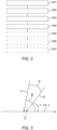
- Fig. 5A to Fig. 7B show two graphs each to explain possible variants for the inventive gas-shielded metal arc welding device, MSLBFG, in particular the gas-shielded metal arc welding device, MSSG 100, as well as for embodiments of the inventive method.
- Part A shows the time course of the first average feed rate Vd_LBTAD of the arc-carrying consumable wire electrode, LBTAD 10
- part B shows the time course of the second average feed rate Vd_AZD of the consumable filler wire, AZD 20.
- Exemplary numerical values in m/min are given, but these are only examples.
- Fig. 5A and 5B illustrate a variant in which the first wire feed speed Vd_LBTAD is set according to different (joining or welding) process phases, namely periodically alternating from a comparatively higher wire feed speed value (which is associated in particular with a comparatively higher welding current at the arc 4) to a comparatively lower wire feed speed value (which is associated in particular with a comparatively lower welding current at the arc 4) and back, for example in the context of a pulse process, in particular a synchropulse process.
- the lower wire feed speed value can be positive, or alternatively zero (not shown). This allows for a more accurately created rippled weld seam. If the first average wire feed speed Vd_LBTAD is zero, arc 4 is typically extinguished, i.e., in this variant, process phases alternate with and without arc 4. If the first average wire feed speed Vd_LBTAD is zero (or low) and the second average wire feed speed Vd_AZD is positive, a more pronounced weld seam ripple pattern can be created, which is often desired.
- the second average wire feed speed Vd_AZD is set synchronously with the process phases of the first average wire feed speed Vd_LBTAD, whereby the higher wire feed speed value of the first average wire feed speed Vd_LBTAD is accompanied by a correspondingly higher wire feed speed value of the second average wire feed speed Vd_AZD, and the lower wire feed speed value of the first average wire feed speed Vd_LBTAD is accompanied by a correspondingly lower wire feed speed value of the second average wire feed speed Vd_AZD.
- the wire feed speed value of the second average wire feed speed Vd_AZD can be positive or also zero.
- the first average wire feed speed Vd_LBTAD is typically high (set) when the deposition rate is high (set) at which the arc-carrying consumable wire electrode, LBTAD 10, is melted, so that sufficient material is always fed to the LBTAD 10 for melting, and the arc 4 does not break.
- the first average wire feed speed Vd_LBTAD is low (set) when the deposition rate is low (set) so that sufficient material is fed to each joint along the joint seam.
- Fig. 6A and 6B illustrate a variant in which the first average wire feed speed Vd_LBTAD is set as in Fig. 5A is set (i.e., pulsating), while the second average wire feed speed Vd_AZD remains constant. Thus, despite different process phases, a constant optimal joining speed is specified or set.
- Fig. 7A and 7B illustrate a variant in which the first average wire feed speed Vd_LBTAD remains constant, while the second average wire feed speed Vd_AZD exhibits periodic process phases.
- the counterforce specifies or sets a periodically changing joining speed (here between two values) on the arc-bearing, consumable wire electrode, LBTAD 10.
- variants according to Fig. 5A to Fig. 7B or further such variants can each be carried out within the scope of the method according to the invention, or the main wire feed device 110 and the additional wire feed device 120 of the metal inert gas arc welding device according to the invention, MSLBFG, or of the additional device according to the invention can be configured accordingly.
Landscapes
- Engineering & Computer Science (AREA)
- Physics & Mathematics (AREA)
- Plasma & Fusion (AREA)
- Mechanical Engineering (AREA)
- Arc Welding In General (AREA)
Priority Applications (3)
| Application Number | Priority Date | Filing Date | Title |
|---|---|---|---|
| EP24206950.8A EP4582207A1 (fr) | 2024-10-16 | 2024-10-16 | Appareil d'assemblage métal-gaz protecteur pour l'assemblage à arc manuel, accessoire pour appareil d'assemblage métal-gaz protecteur pour l'assemblage à arc et procédé d'assemblage |
| PCT/EP2025/075951 WO2026082351A1 (fr) | 2024-10-16 | 2025-09-11 | Appareil d'assemblage à l'arc sous protection gazeuse pour assemblage à l'arc manuel, appareil auxiliaire pour un appareil d'assemblage à l'arc sous protection gazeuse pour assemblage à l'arc manuel et procédé d'assemblage à l'arc manuel sous protection gazeuse |
| EP25201650.6A EP4737042A2 (fr) | 2024-10-16 | 2025-09-11 | Appareil d'assemblage d'arc sous gaz protecteur et métal pour l'assemblage d'arc manuel et procédé d'assemblage d'arc manuel |
Applications Claiming Priority (1)
| Application Number | Priority Date | Filing Date | Title |
|---|---|---|---|
| EP24206950.8A EP4582207A1 (fr) | 2024-10-16 | 2024-10-16 | Appareil d'assemblage métal-gaz protecteur pour l'assemblage à arc manuel, accessoire pour appareil d'assemblage métal-gaz protecteur pour l'assemblage à arc et procédé d'assemblage |
Publications (1)
| Publication Number | Publication Date |
|---|---|
| EP4582207A1 true EP4582207A1 (fr) | 2025-07-09 |
Family
ID=93150146
Family Applications (2)
| Application Number | Title | Priority Date | Filing Date |
|---|---|---|---|
| EP24206950.8A Pending EP4582207A1 (fr) | 2024-10-16 | 2024-10-16 | Appareil d'assemblage métal-gaz protecteur pour l'assemblage à arc manuel, accessoire pour appareil d'assemblage métal-gaz protecteur pour l'assemblage à arc et procédé d'assemblage |
| EP25201650.6A Pending EP4737042A2 (fr) | 2024-10-16 | 2025-09-11 | Appareil d'assemblage d'arc sous gaz protecteur et métal pour l'assemblage d'arc manuel et procédé d'assemblage d'arc manuel |
Family Applications After (1)
| Application Number | Title | Priority Date | Filing Date |
|---|---|---|---|
| EP25201650.6A Pending EP4737042A2 (fr) | 2024-10-16 | 2025-09-11 | Appareil d'assemblage d'arc sous gaz protecteur et métal pour l'assemblage d'arc manuel et procédé d'assemblage d'arc manuel |
Country Status (2)
| Country | Link |
|---|---|
| EP (2) | EP4582207A1 (fr) |
| WO (1) | WO2026082351A1 (fr) |
Citations (3)
| Publication number | Priority date | Publication date | Assignee | Title |
|---|---|---|---|---|
| EP1009575B1 (fr) * | 1997-02-19 | 2003-06-11 | La Soudure Autogène Française | Modele perfectionne de tete de soudage et procede d'utilisation |
| US20150048057A1 (en) * | 2012-03-29 | 2015-02-19 | Taiyo Nippon Sanso Corporation | Semi-automatic welding system, conversion adapter kit, and welding torch |
| EP4442399A1 (fr) * | 2023-02-27 | 2024-10-09 | Illinois Tool Works Inc. | Procédés et appareil de commande de soudage tig |
Family Cites Families (3)
| Publication number | Priority date | Publication date | Assignee | Title |
|---|---|---|---|---|
| GB727484A (en) * | 1951-04-26 | 1955-04-06 | Air Reduction | Method and apparatus for welding |
| US2778099A (en) * | 1952-05-15 | 1957-01-22 | Air Reduction | Method of welding and apparatus therefor |
| US10035211B2 (en) * | 2013-03-15 | 2018-07-31 | Lincoln Global, Inc. | Tandem hot-wire systems |
-
2024
- 2024-10-16 EP EP24206950.8A patent/EP4582207A1/fr active Pending
-
2025
- 2025-09-11 EP EP25201650.6A patent/EP4737042A2/fr active Pending
- 2025-09-11 WO PCT/EP2025/075951 patent/WO2026082351A1/fr active Pending
Patent Citations (3)
| Publication number | Priority date | Publication date | Assignee | Title |
|---|---|---|---|---|
| EP1009575B1 (fr) * | 1997-02-19 | 2003-06-11 | La Soudure Autogène Française | Modele perfectionne de tete de soudage et procede d'utilisation |
| US20150048057A1 (en) * | 2012-03-29 | 2015-02-19 | Taiyo Nippon Sanso Corporation | Semi-automatic welding system, conversion adapter kit, and welding torch |
| EP4442399A1 (fr) * | 2023-02-27 | 2024-10-09 | Illinois Tool Works Inc. | Procédés et appareil de commande de soudage tig |
Also Published As
| Publication number | Publication date |
|---|---|
| EP4737042A2 (fr) | 2026-05-06 |
| WO2026082351A1 (fr) | 2026-04-23 |
Similar Documents
| Publication | Publication Date | Title |
|---|---|---|
| EP1812200B2 (fr) | Dispositif pour la mise en oeuvre d'un procede de traitement de surface, d'assemblage ou de separation, en particulier d'un procede de soudage | |
| DE60131935T2 (de) | Ein Laserstrahlbearbeitungskopf und eine Laserbearbeitungsvorrichtung mit einem solchen Laserstrahlbearbeitungskopf | |
| DE212014000085U1 (de) | Tandem-Warmdrahtsysteme | |
| DE102012218487B4 (de) | Verfahren und Vorrichtung zur Herstellung einer dreidimensionalen Struktur an der Oberfläche eines metallischen Werkstücks | |
| EP2644306A1 (fr) | Dispositif de soudage et procédé de réglage d'un procédé de soudage | |
| EP2216122A1 (fr) | Tuyau à gaz de protection et tuyau de contact d'un dispositif destiné à la soudure améliorée d'intervalles serrés | |
| EP3370911B1 (fr) | Procede de rechargement par soudure | |
| EP3623095A1 (fr) | Appareil de soudage et procédé de soudage à vitesse d'avance du fil de soudage à réglage automatique | |
| EP4582207A1 (fr) | Appareil d'assemblage métal-gaz protecteur pour l'assemblage à arc manuel, accessoire pour appareil d'assemblage métal-gaz protecteur pour l'assemblage à arc et procédé d'assemblage | |
| EP2216120A1 (fr) | Tuyau à gaz de protection et tuyau de contact d'un dispositif destiné à la soudure améliorée d'intervalles serrés | |
| DE102014206767B3 (de) | Verfahren und Vorrichtung zur Messung von Pulverströmen eines Laserschweißwerkzeugs | |
| EP3459668B1 (fr) | Procédé de soudage sous gaz de protection pour soudage en bouchon | |
| EP4263105B1 (fr) | Procédé de soudage multiple | |
| WO2024218083A1 (fr) | Procédé d'assemblage à l'arc multiple | |
| EP2277655B1 (fr) | Procédé et dispositif destiné au soudage 'keyhole' par plasma avec modification de l'écoulment volumique et/ou de la composition du gaz en fonction de conditions limites du procédé de soudage | |
| EP3960352B1 (fr) | Réglage de la position d'une tête de soudage tandem | |
| EP4025372B1 (fr) | Method et dispositif pour conduire un procédé de soudage multiple | |
| EP1980354B1 (fr) | Procédé pour soudage en bouchon au moyen de plasma | |
| EP3424636B1 (fr) | Système de soudage laser comprenant un dispositif pousseur, une optique d'usinage et au moins un dispositif de guidage tactile | |
| AT513428B1 (de) | Verfahren zur Herstellung einer dreidimensionalen Struktur an der Oberfläche eines metallischen Werkstücks | |
| EP3953091B1 (fr) | Procédé de soudage multiple | |
| DE2325059A1 (de) | Verfahren und vorrichtung zum lichtbogenschweissen, insbesondere unterpulverschweissen | |
| EP4208309B1 (fr) | Procédé de préparation d'un procédé de soudage automatisé pour un processus de soudage et dispositif de soudage destiné à la mise en uvre d'un procédé de soudage automatisé | |
| DE10126032C1 (de) | Vorrichtung zur Laserbearbeitung | |
| DE102009027785A1 (de) | Verfahren und Vorrichtung zum Plasma-Stichlochschweißen |
Legal Events
| Date | Code | Title | Description |
|---|---|---|---|
| PUAI | Public reference made under article 153(3) epc to a published international application that has entered the european phase |
Free format text: ORIGINAL CODE: 0009012 |
|
| STAA | Information on the status of an ep patent application or granted ep patent |
Free format text: STATUS: THE APPLICATION HAS BEEN PUBLISHED |
|
| AK | Designated contracting states |
Kind code of ref document: A1 Designated state(s): AL AT BE BG CH CY CZ DE DK EE ES FI FR GB GR HR HU IE IS IT LI LT LU LV MC ME MK MT NL NO PL PT RO RS SE SI SK SM TR |
|
| STAA | Information on the status of an ep patent application or granted ep patent |
Free format text: STATUS: THE APPLICATION IS DEEMED TO BE WITHDRAWN |