EP4582232A1 - Bol en bois pour un batteur sur socle et méthode de fabrication du bol de mélange - Google Patents
Bol en bois pour un batteur sur socle et méthode de fabrication du bol de mélange Download PDFInfo
- Publication number
- EP4582232A1 EP4582232A1 EP25150580.6A EP25150580A EP4582232A1 EP 4582232 A1 EP4582232 A1 EP 4582232A1 EP 25150580 A EP25150580 A EP 25150580A EP 4582232 A1 EP4582232 A1 EP 4582232A1
- Authority
- EP
- European Patent Office
- Prior art keywords
- lamination
- bowl
- mixing bowl
- layers
- widths
- Prior art date
- Legal status (The legal status is an assumption and is not a legal conclusion. Google has not performed a legal analysis and makes no representation as to the accuracy of the status listed.)
- Pending
Links
Images







Classifications
-
- A—HUMAN NECESSITIES
- A47—FURNITURE; DOMESTIC ARTICLES OR APPLIANCES; COFFEE MILLS; SPICE MILLS; SUCTION CLEANERS IN GENERAL
- A47J—KITCHEN EQUIPMENT; COFFEE MILLS; SPICE MILLS; APPARATUS FOR MAKING BEVERAGES
- A47J43/00—Implements for preparing or holding food, not provided for in other groups of this subclass
- A47J43/04—Machines for domestic use not covered elsewhere, e.g. for grinding, mixing, stirring, kneading, emulsifying, whipping or beating foodstuffs, e.g. power-driven
- A47J43/07—Parts or details, e.g. mixing tools, whipping tools
- A47J43/0727—Mixing bowls
-
- B—PERFORMING OPERATIONS; TRANSPORTING
- B01—PHYSICAL OR CHEMICAL PROCESSES OR APPARATUS IN GENERAL
- B01F—MIXING, e.g. DISSOLVING, EMULSIFYING OR DISPERSING
- B01F35/00—Accessories for mixers; Auxiliary operations or auxiliary devices; Parts or details of general application
- B01F35/50—Mixing receptacles
- B01F35/51—Mixing receptacles characterised by their material
-
- A—HUMAN NECESSITIES
- A47—FURNITURE; DOMESTIC ARTICLES OR APPLIANCES; COFFEE MILLS; SPICE MILLS; SUCTION CLEANERS IN GENERAL
- A47J—KITCHEN EQUIPMENT; COFFEE MILLS; SPICE MILLS; APPARATUS FOR MAKING BEVERAGES
- A47J43/00—Implements for preparing or holding food, not provided for in other groups of this subclass
- A47J43/04—Machines for domestic use not covered elsewhere, e.g. for grinding, mixing, stirring, kneading, emulsifying, whipping or beating foodstuffs, e.g. power-driven
- A47J43/044—Machines for domestic use not covered elsewhere, e.g. for grinding, mixing, stirring, kneading, emulsifying, whipping or beating foodstuffs, e.g. power-driven with tools driven from the top side
-
- B—PERFORMING OPERATIONS; TRANSPORTING
- B01—PHYSICAL OR CHEMICAL PROCESSES OR APPARATUS IN GENERAL
- B01F—MIXING, e.g. DISSOLVING, EMULSIFYING OR DISPERSING
- B01F27/00—Mixers with rotary stirring devices in fixed receptacles; Kneaders
- B01F27/80—Mixers with rotary stirring devices in fixed receptacles; Kneaders with stirrers rotating about a substantially vertical axis
- B01F27/90—Mixers with rotary stirring devices in fixed receptacles; Kneaders with stirrers rotating about a substantially vertical axis with paddles or arms
-
- B—PERFORMING OPERATIONS; TRANSPORTING
- B27—WORKING OR PRESERVING WOOD OR SIMILAR MATERIAL; NAILING OR STAPLING MACHINES IN GENERAL
- B27M—WORKING OF WOOD NOT PROVIDED FOR IN SUBCLASSES B27B - B27L; MANUFACTURE OF SPECIFIC WOODEN ARTICLES
- B27M3/00—Manufacture or reconditioning of specific semi-finished or finished articles
- B27M3/24—Manufacture or reconditioning of specific semi-finished or finished articles of household utensils, e.g. spoons, clothes hangers, clothes pegs
-
- A—HUMAN NECESSITIES
- A47—FURNITURE; DOMESTIC ARTICLES OR APPLIANCES; COFFEE MILLS; SPICE MILLS; SUCTION CLEANERS IN GENERAL
- A47J—KITCHEN EQUIPMENT; COFFEE MILLS; SPICE MILLS; APPARATUS FOR MAKING BEVERAGES
- A47J43/00—Implements for preparing or holding food, not provided for in other groups of this subclass
- A47J43/04—Machines for domestic use not covered elsewhere, e.g. for grinding, mixing, stirring, kneading, emulsifying, whipping or beating foodstuffs, e.g. power-driven
- A47J43/044—Machines for domestic use not covered elsewhere, e.g. for grinding, mixing, stirring, kneading, emulsifying, whipping or beating foodstuffs, e.g. power-driven with tools driven from the top side
- A47J2043/04454—Apparatus of counter top type
Definitions
- the present disclosure generally relates to a combined wooden and metal bowl for a KitchenAid stand mixer, and more specifically, to a wooden bowl with a metal liner that is configured for use with a stand mixer.
- a mixing bowl includes a bowl body defining an exterior and an interior cavity and comprising a plurality of lamination segments.
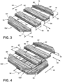
- the lamination segments consist essentially of wood and are arranged in alternating layers of first and second types along a height of the bowl body with the layers of the first type including respective ones of the lamination segments having widths extending in a first lateral direction with respect to the bowl body and coupled together along joints extending in a second lateral direction with respect to the bowl body.
- the second lateral direction is perpendicular to the first lateral direction.
- the layers of the second type include respective ones of the lamination segments having widths extending in the second lateral direction with respect to the bowl body and are coupled together along joints extending in the first lateral direction with respect to the bowl body.
- a method for making a mixing bowl includes assembling a plurality of lamination layers from a respective plurality of wood boards.
- Each of the wood boards define a width across a grain structure of the board and are coupled together at respective joints therebetween extending along respective lengths of the wood boards.
- the lamination layers each have a height corresponding with a thickness of the wood boards in directions normal to the widths and lengths thereof.
- the method also includes joining the lamination layers together in a direction corresponding with the respective heights of the lamination layers to form a blank.
- the lamination layers are successively arranged in alternating first and second orientations.
- the first orientation is such that the respective lengths of the wood boards extend in a first direction
- the second orientation is such that the respective lengths of the wood boards extend in a second direction perpendicular to the first direction.
- the method further includes shaping the blank into a bowl body defining an exterior and an interior cavity.
- a mixing bowl for a stand mixer includes a bowl body defining an exterior and an interior cavity and shaped from a blank having plurality of lamination layers.
- Each of the lamination layers are assembled from a respective plurality of wood boards.
- Each of the wood boards defines a width across a grain structure of the board and coupled together at respective joints therebetween extending along respective lengths of the wood boards.
- the lamination layers each have a height corresponding with a thickness of the wood boards in directions normal to the widths and lengths thereof.
- the lamination layers are joined together in a direction corresponding with the respective heights of the lamination layers to form the blank.
- the lamination layers are successively arranged in alternating first and second orientations.
- the first orientation has the respective lengths of the wood boards extending in a first direction
- the second orientation has the respective lengths of the wood boards extending in a second direction perpendicular to the first direction.
- the mixing bowl for the stand mixer further includes a coating applied over at least a majority of the bowl body and a mounting base coupled with the bowl body on the exterior thereof and configured to couple the mixing bowl with a retention feature of a stand mixer.
- a mixing bowl for a stand mixer includes an outer body consisting essentially of wood and defining an exterior and an interior cavity and a liner consisting essentially of metal and coupled within the interior cavity of the outer body so as to define an interior surface of the mixing bowl.
- a mounting base is coupled with the outer body on the exterior thereof and is configured to couple the mixing bowl with a retention feature of the stand mixer.
- a mixing bowl for a stand mixer includes an outer body consisting essentially of wood and defining an exterior, an interior cavity, an upper edge between the exterior and the interior cavity, and a groove extending inwardly from an interior wall defining the interior cavity adjacent the upper edge.
- the mixing bowl also includes a liner having an upper flange, consisting essentially of metal, and being coupled within the interior cavity of the outer body at least by receipt of the upper flange within the groove of the outer body so as to define an interior surface of the mixing bowl.
- the mixing head H encloses a drive motor that is configured to drive planetary movement of the output O, as described above, as well as rotating a coupling within the attachment hub C.
- the drive motor can be a variable speed AC motor that can be controlled by a user via a sliding control knob accessible on the exterior of the mixing head H.
- the drive motor can be a DC motor, including a brushless DC motor that can be controlled digitally using an adaptation of the control knob or using a digital interface.
- the resulting mixing bowl 10 can be configured with the bowl body 12 having a wall thickness T of about 1 ⁇ 2 inch, or in a more specific example, 0.47 inches, or in a further specific example, 0.472 inches (given acceptable tolerancing corresponding with such dimensioning).
- the overall height H of the mixing bowl 10 can be about 7.5" (+/- .01") with an outer diameter D of about 9.4" and an inner diameter of about 8.4". It is to be appreciated that the method described herein can be used to fabricate different types of bowls with varying configurations and/or varying dimensions to those shown and described herein.
- the step of shaping the blank 12' into the bowl body 12 can be carried out by selectively removing material from the blank 12' using a mechanical process.
- a mechanical process can be carried out using a lathe, a mill, or the like, and may be finished using a sanding process. Any of these processes can be carried out using a manually-controlled machine or an automated machine (i.e., a CNC lathe or a CNC mill) or various combinations thereof.
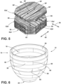
- the shaping of the bowl body 12 in particular dimensions relative to the above-described dimensions of the wood boards 50' may result in certain ones of the joints 58 aligning vertically between successive layers 52a and 52b or being within a predetermined range (e.g., 1 cm) of vertical alignment that may not be desired.
- the degree to which the subject lamination layers 52a' or 52b' are offset can vary depending on the positioning of the relevant joints 58a and the other affected joints 58 such that the offset removes the relevant aligned condition without introducing other aligned conditions in other affected joints 58.
- lamination layers 52a o ' in one orientation are joined respectively above and below another lamination layer 52b o ' that is the other orientation (i.e., perpendicular to layers 52a o ') with the lamination layers 52a o ' being offset relative to each other.
- both layers 52a o ' are both offset relative to the other lamination layer 52a' in the same orientation, but in some examples only one of the lamination layers 52a o ' may be offset in this manner, similar to the intermediate layer 52b o '.
- this offsetting results (and may be evidenced by) the joints 58' between the boards 50' (and the joints 58 between segments 50) in the lower lamination layer 58a o ' being offset from the boards in the other comparative lamination layer 52a o ' in the relevant direction 60.
- the effect of this offsetting on the resulting bowl body 12 is shown in FIG. 8 .
- the bowl body 12 after the bowl body 12 is shaped, it can be coated with a polymeric material to help seal the bowl body 12 from liquid intrusion and/or to increase the durability of the resulting mixing bowl 10.
- the coating can be of a polymeric material and can be one designated as safe for food contact.
- such a coating can be of polyurethane, which can be applied by spraying, painting, dipping or the like. The coating can be applied over the entire bowl body 12 or, some examples, only within the interior cavity 16 or on the entire bowl body 12, except along portions of the base portion 24 not covered by the mounting base 22.
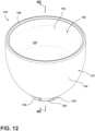
- reference numeral 110 generally designates a mixing bowl for a stand mixer S (as shown in FIG. 2 ) according to another aspect of the disclosure.
- the mixing bowl 110 includes an outer body 112 consisting essentially of wood and defining an exterior 114 and an interior cavity 116.
- the mixing bowl 110 also includes a liner 118 consisting essentially of metal and coupled within the interior cavity 116 of the outer body 112 so as to define an interior surface 120 of the mixing bowl 110.
- a mounting base 122 is coupled with the outer body 112 on the exterior 114 thereof and is configured to couple the mixing bowl 110 with a retention feature of the stand mixer S.
- the interaction of the various types of tools that can be used in connection with the stand mixer S to process ingredients within the mixing bowl 110 can subject the interior surface 120 thereof to repeated impacts and scraping from the utilized mixing tool.
- certain implementations of the beater attachment A shown herein may have rubber "flex edges", other implementations thereof, as well as other tools such as whisks, and dough hooks can be of metal. Whisks, in particular may be configured to make intentional, periodic contact with the interior surface 120 of the mixing bowl. When such tools are used in connection with a wooden mixing bowl, the periodic contact of metal tools with the interior, as well as frequent interior cleaning may lead to undesirable wear to the interior surface thereof.
- the present mixing bowl incorporates the above-mentioned metal liner 118 to provide a durable interior surface 120 for the mixing bowl 110, which includes outer body 112 of wood, which may be preferred by some consumers for aesthetic purposes, as well as for weight savings and environmental concerns.
- the interior surface 120 defined on the metal liner 118 can offer improved durability over wooden bowls with no such liners, as well as some plastic bowls.
- the liner 118 can define a second material thickness T2 of between 2 mm and 3 mm, for example.
- the thicknesses T1 and T2 listed herein may vary by the particular type or species of wood used for the outer body 112 and the type of metal of the liner 118.
- the outer body 112 can be fabricated from various types of hardwoods including, but not limited to, walnut, olive, teak, mahogany, oak, ash, birch, or the like.
- the outer body 112 can be formed from a blank of the desired type of wood by various woodworking processes, including but not limited to wood turning (i.e., using a lathe, which may be computer controlled and may involve separate processes and/or machinery for shaping the exterior 114 and interior cavity 116), CNC milling, or the like.
- the blank can comprise multiple pieces of the selected wood joined together, for example by gluing or the like, in an arrangement selected according to the wood species (for example, the hardness, strength, grain profile, etc.
- the thickness T1 of the outer body 112 can, accordingly vary based on the selection of any or all of these features or processes (species, blank composition, fabrication), as well as the general geometry of the mixing bowl 110. In this manner, the thickness T1 may not be consistent throughout the entire profile of the outer body 112, but may vary to provide additional strength or material, in general, in certain areas of the outer body 112, as discussed in some examples below.
- at least the exterior 114 e.g., any portions of the outer body 112 not covered by the liner 118
- an acceptable coating material such as various food-grade polyurethanes, natural waxes, oils or the like.
- the thickness T2 of the liner 118 can vary depending on the selected metal, which may be aluminum, copper, stainless steel, or the like, as well as the fabrication process.
- the liner 118 can be formed using a metal spinning process, a deep-drawing process, or the like.
- some harder metals, such as stainless steel may accommodate a thinner profile than relatively softer, or more malleable, material, such as copper or the like.
- some processes may require a thicker material or may result in a thinner overall profile at varying degrees of uniformity.
- the liner 118 can be coupled with the outer body by an adhesive layer 125 at least partially disposed between the liner 118 and the underlying portions of the outer body 112.
- the location and quantity of the adhesive can vary depending on the type of adhesive used.
- the entire outer surface 127 of the liner 118 can be coated with the adhesive 125 (it being understood that the adhesive 125 can be applied to the corresponding portion(s) of the outer body 112).
- the adhesive layer 125 can include multiple portions applied, for example, in a ring adjacent the upper end of the liner 118 and toward the bottom thereof and/or in vertical strips extending along the height of the liner 118 in, for example, 45°, 30°, or 20° intervals.
- certain adhesives designated as useable in food-related applications can be used (although the adhesive layer 125 is not presently contemplated as being in a location where contact with the actual food product would be made.
- Such adhesives may exhibit good workability, low viscosity, and high molecular weight and may include certain pressure-sensitive adhesives, laminating adhesives (including acrylic and urethane adhesives, which may be cross-linked with aliphatic poly-isocyanates), hot melt adhesives.
- the angled flanges 132 can be formed directly in the wood material of the outer body 112 (such as by CNC milling or the like) or, for improved strength or durability, can be formed on a metal base unit 134 that can generally define the mounting base 122 when couple don the base portion 124 of the outer body 112, as shown for example in FIG. 13 .
- the base unit 134 can be generally cup-shaped so as to receive the base portion 124 of the outer body 112 therein and can define a circular outer profile sized to fit in the example bowl mount M and including the above-described plurality of angled flanges 132 extending outwardly therefrom.
- a mixing bowl 110 including a wooden outer body 112 and a metal liner 118 according to the disclosure herein can be adapted to work with a bowl-lift type stand mixer, as is known in the art.
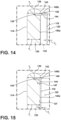
- the groove 138 may be positioned immediately adjacent the transition point 142 (or the end of the upper edge 136) such that no discernable portion of an upper portion 140a of the interior wall 140 is present.
- the liner 118 can include an upper flange 144 received in the groove. This arrangement can help retain the liner 118 within the interior cavity 116 and can provide for improved sealing of the upper edge 145 of the liner 118 with the outer body 112, by embedding a portion of the liner 118 beyond the upper edge 145 (i.e., the upper flange 144) within the outer body 112. As shown in FIG.
- the outer body 112 may comprise a lower portion 112a and an upper portion 112b joined with the lower portion at an interface 148.
- the lower portion 112a and the upper portion 112b may collectively define the groove 138 in a way such that the groove 138 extends from, or is otherwise contiguous with, the interface 148.
- the groove 138 can be initially formed as an open ridge 138' in the lower portion 112a, as shown in FIG. 16 .
- the groove 138 can be similarly initially formed in the upper portion 112b or can be formed by shallower ridges in each of the lower portion 112a and the upper portion 112b.
- the outer bowl can be sanded or otherwise smoothed along the interface 148 at the exterior 114 to provide a generally seamless appearance for the resulting outer body 112, which can then be subjected to a finish process, as described above, or a final stage of such a finish process (with the interior surface 120 being appropriately masked.
- the outer body 112 may include multiple layers of wood material, including within the lower portion 112a, with the upper portion 112a forming or otherwise appearing as one of such layers.
- plating layer 218 When plating layer 218 is formed with an electroplating process, it may be desired to apply a thin metallic layer 250 to the interior surface 220, which may be applied as a metallic paint or the like. This may be beneficial in creating an electrode base for plating onto the layer 250 and, accordingly onto the outer body 212. By any such process, after the plating layer 218 is formed, it can be polished or finished using other processes, such as brushing, or the like.
- a mixing bowl includes a bowl body defining an exterior and an interior cavity and comprising a plurality of lamination segments.
- the lamination segments consist essentially of wood and are arranged in alternating layers of first and second types along a height of the bowl body with the layers of the first type including respective ones of the lamination segments having widths extending in a first lateral direction with respect to the bowl body and coupled together along joints extending in a second lateral direction with respect to the bowl body.
- the second lateral direction is perpendicular to the first lateral direction.
- the layers of the second type include respective ones of the lamination segments having widths extending in the second lateral direction with respect to the bowl body and are coupled together along joints extending in the first lateral direction with respect to the bowl body.
- the layers of each of the first and second types can be configured such that each of the respective layer segments therein have a common height in the direction of the height of the bowl body such that each of the layers defines a height.
- the height of each layer can be approximately 1 inch.
- the widths of the lamination segments in the first layer type and the widths of the lamination segments in the second layer type can be between 2.5 inches and 3.5 inches.
- the lamination segments in the first layer type and the lamination segments in the second layer type can be coupled together along the respective joints using an adhesive.
- the alternating layers of first and second types can be coupled together using an adhesive.
- the wood in the mixing bowl of any of UU 60 to 65, the wood can be walnut.
- the lamination segments can be shaped portions of laminated boards having widths corresponding with the respective widths of the lamination segments, the widths of the lamination segments extending across a grain direction of the laminated boards.
- the mixing bowl of any of UU 60 to 67 can further include a coating of a polymeric material applied over at least a majority of the bowl body.
- the mixing bowl of any of UU 60 to 68 can further include a mounting base coupled with the bowl body on the exterior thereof and configured to couple the mixing bowl with a retention feature of a stand mixer.
- a method for making a mixing bowl includes assembling a plurality of lamination layers from a respective plurality of wood boards.
- Each of the wood boards define a width across a grain structure of the board and are coupled together at respective joints therebetween extending along respective lengths of the wood boards.
- the lamination layers each have a height corresponding with a thickness of the wood boards in directions normal to the widths and lengths thereof.
- the method also includes joining the lamination layers together in a direction corresponding with the respective heights of the lamination layers to form a blank.
- the lamination layers are successively arranged in alternating first and second orientations.
- the first orientation is such that the respective lengths of the wood boards extend in a first direction
- the second orientation is such that the respective lengths of the wood boards extend in a second direction perpendicular to the first direction.
- the method further includes shaping the blank into a bowl body defining an exterior and an interior cavity.
- the height of each of the lamination layers can be approximately 1 inch.
- the widths of the wood boards can be between 2.5 inches and 3.5 inches.
- the lamination layers can be joined together along mutual interfaces therebetween using an adhesive.
- assembling the plurality of lamination layers can include coupling the wood boards together along the respective joints using an adhesive.
- shaping the blank into the bowl body is such that wood boards are respectively reconfigured as lamination segments that are shaped portions of the respective boards having widths corresponding with the respective widths of the lamination segments, the widths of the lamination segments extending across a grain direction of the laminated boards.
- the method of any of UU 70 to 75 can further include applying a coating of a polymeric material over at least a majority of the bowl body.
- the method of any of UU 70 to 76 can further include coupling a mounting base with the bowl body on the exterior thereof and configured to couple the mixing bowl with a retention feature of a stand mixer.
- the step of shaping the blank into the bowl body can be carried out by selectively removing material from the blank using a mechanical process.
- joining the plurality of lamination layers together can include joining a first lamination layer in the first orientation with a second lamination layer in the second orientation and joining a third lamination layer in the first orientation with the second lamination layer opposite the first lamination layer, the joints between the boards in the first lamination layer being offset from the boards in the third lamination layer in the second direction.
- a mixing bowl for a stand mixer includes a bowl body defining an exterior and an interior cavity and shaped from a blank having plurality of lamination layers.
- Each of the lamination layers are assembled from a respective plurality of wood boards.
- Each of the wood boards defines a width across a grain structure of the board and coupled together at respective joints therebetween extending along respective lengths of the wood boards.
- the lamination layers each have a height corresponding with a thickness of the wood boards in directions normal to the widths and lengths thereof.
- the lamination layers are joined together in a direction corresponding with the respective heights of the lamination layers to form the blank.
- the lamination layers are successively arranged in alternating first and second orientations.
- a mixing bowl for a stand mixer includes an outer body consisting essentially of wood and defining an exterior and an interior cavity and a liner consisting essentially of metal and coupled within the interior cavity of the outer body so as to define an interior surface of the mixing bowl.
- a mounting base is coupled with the outer body on the exterior thereof and is configured to couple the mixing bowl with a retention feature of the stand mixer.
- the lower portion of the body may comprise multiple layers of wood coupled together.
- a mixing bowl for a stand mixer includes an outer body consisting essentially of wood and defining an exterior, an interior cavity, an upper edge between the exterior and the interior cavity, and a groove extending inwardly from an interior wall defining the interior cavity adjacent the upper edge.
- the mixing bowl also includes a liner having an upper flange, consisting essentially of metal, and being coupled within the interior cavity of the outer body at least by receipt of the upper flange within the groove of the outer body so as to define an interior surface of the mixing bowl.
- the mixing bowl of U 90 may further include a mounting base coupled with the outer body on the exterior thereof and configured to couple the mixing bowl with a retention feature of a stand mixer.
- the outer body can define a first material thickness of between 10 mm and about 15 mm along a portion thereof with which the liner is coupled, and the liner can define a second material thickness of between 2 mm and 3 mm.
- a method for making a mixing bowl for a stand mixer can include coupling a metal liner within an interior cavity of an outer body so as to define an interior surface of the mixing bowl.
- the outer body consists essentially of wood and defines an exterior and the interior cavity.
- the method further includes coupling a mounting base with the outer body on the exterior thereof.
- the mounting base is configured to couple the mixing bowl with a retention feature of a stand mixer.
- the outer body can comprise a lower portion and an upper portion
- positioning the upper flange of the liner in the groove can include joining the upper portion with the lower portion at a junction, the lower portion and the upper portion collectively defining the groove extending from the interface with the upper flange of the liner positioned therein.
- the liner can be coupled within the interior cavity of the outer body by applying the liner as a metal plating layer to the outer body by a metallic plating process.
- the metallic plating process may include an initial step of applying a metallic paint layer to an interior wall of the outer body, and the method may further include polishing the plating layer along the interior surface of the mixing bowl.
Landscapes
- Engineering & Computer Science (AREA)
- Life Sciences & Earth Sciences (AREA)
- Mechanical Engineering (AREA)
- Food Science & Technology (AREA)
- Manufacturing & Machinery (AREA)
- Wood Science & Technology (AREA)
- Forests & Forestry (AREA)
- Chemical & Material Sciences (AREA)
- Chemical Kinetics & Catalysis (AREA)
- Food-Manufacturing Devices (AREA)
Applications Claiming Priority (1)
| Application Number | Priority Date | Filing Date | Title |
|---|---|---|---|
| US18/406,950 US20250221574A1 (en) | 2024-01-08 | 2024-01-08 | Wood bowl for a stand mixer and related methods |
Publications (1)
| Publication Number | Publication Date |
|---|---|
| EP4582232A1 true EP4582232A1 (fr) | 2025-07-09 |
Family
ID=94227811
Family Applications (1)
| Application Number | Title | Priority Date | Filing Date |
|---|---|---|---|
| EP25150580.6A Pending EP4582232A1 (fr) | 2024-01-08 | 2025-01-07 | Bol en bois pour un batteur sur socle et méthode de fabrication du bol de mélange |
Country Status (4)
| Country | Link |
|---|---|
| US (1) | US20250221574A1 (fr) |
| EP (1) | EP4582232A1 (fr) |
| CN (1) | CN120268301A (fr) |
| AU (1) | AU2025200100A1 (fr) |
Citations (5)
| Publication number | Priority date | Publication date | Assignee | Title |
|---|---|---|---|---|
| JPS52115687U (fr) * | 1976-02-26 | 1977-09-02 | ||
| JPH09169328A (ja) * | 1995-12-15 | 1997-06-30 | Tachibana Shokai:Kk | トレー及びその製造方法 |
| JP4449065B2 (ja) * | 2004-03-11 | 2010-04-14 | 宮崎県 | 木質深底容器 |
| CN103448126A (zh) * | 2013-08-29 | 2013-12-18 | 建阳泰和竹木制品有限公司 | 一种竹碗生产工艺 |
| CN104290167A (zh) * | 2014-06-19 | 2015-01-21 | 宁波士林工艺品有限公司 | 竹碗生产工艺及其产品 |
Family Cites Families (7)
| Publication number | Priority date | Publication date | Assignee | Title |
|---|---|---|---|---|
| US1465383A (en) * | 1920-03-17 | 1923-08-21 | Frank J Walsh | Composite lumber |
| US2062175A (en) * | 1935-12-10 | 1936-11-24 | Frank H Hartman | Method of manufacturing inlaid wood articles |
| US3153433A (en) * | 1961-08-16 | 1964-10-20 | Ferrara Dominick | Method of making bowls and the like |
| US3345240A (en) * | 1964-06-03 | 1967-10-03 | John E O'herron | Hobby craft device |
| US3956542A (en) * | 1974-07-15 | 1976-05-11 | Barney Roberti | Multiple ply wood article and method |
| US6162312A (en) * | 1999-01-19 | 2000-12-19 | Abney; Dennis R. | Method of making a resin impregnated composite wood product from waste, scrap, and used wood |
| ITMI20022384A1 (it) * | 2002-11-11 | 2004-05-12 | Classwood S R L | Sanitari da bagno in legno e procedimento per la loro produzione. |
-
2024
- 2024-01-08 US US18/406,950 patent/US20250221574A1/en active Pending
-
2025
- 2025-01-07 EP EP25150580.6A patent/EP4582232A1/fr active Pending
- 2025-01-08 AU AU2025200100A patent/AU2025200100A1/en active Pending
- 2025-01-08 CN CN202510028681.0A patent/CN120268301A/zh active Pending
Patent Citations (5)
| Publication number | Priority date | Publication date | Assignee | Title |
|---|---|---|---|---|
| JPS52115687U (fr) * | 1976-02-26 | 1977-09-02 | ||
| JPH09169328A (ja) * | 1995-12-15 | 1997-06-30 | Tachibana Shokai:Kk | トレー及びその製造方法 |
| JP4449065B2 (ja) * | 2004-03-11 | 2010-04-14 | 宮崎県 | 木質深底容器 |
| CN103448126A (zh) * | 2013-08-29 | 2013-12-18 | 建阳泰和竹木制品有限公司 | 一种竹碗生产工艺 |
| CN104290167A (zh) * | 2014-06-19 | 2015-01-21 | 宁波士林工艺品有限公司 | 竹碗生产工艺及其产品 |
Also Published As
| Publication number | Publication date |
|---|---|
| US20250221574A1 (en) | 2025-07-10 |
| CN120268301A (zh) | 2025-07-08 |
| AU2025200100A1 (en) | 2025-07-24 |
Similar Documents
| Publication | Publication Date | Title |
|---|---|---|
| US20130305635A1 (en) | Stair tread overlay and manufacturing process | |
| RU2302498C2 (ru) | Механическая запирающая система для досок настила | |
| EP2342047B1 (fr) | Procédé et appareil de polissage à basse pression | |
| CA2733488C (fr) | Panneau en matiere plastique avec profil a crochet | |
| CN100351480C (zh) | 包括连接元件的多构件的装置以及用于制造可相互连接的构件的方法 | |
| US5147486A (en) | Building plywood product and method | |
| US10100528B2 (en) | Fiber polymer trim | |
| US20060150539A1 (en) | Stair nosing profile | |
| US5534295A (en) | Polyurea/polyurethane edge coating and process for making | |
| US5071688A (en) | Building plywood product | |
| US20250221574A1 (en) | Wood bowl for a stand mixer and related methods | |
| US20210262244A1 (en) | System and method for installation of molding | |
| US3355196A (en) | Smooth joint for structural sheets and members | |
| JPH07102534B2 (ja) | 溝付き化粧板の製造方法 | |
| US20070125448A1 (en) | Assembly and method for providing an interlocking angular end joint | |
| KR101282562B1 (ko) | 건칠 방식을 이용한 목재 접시 제조방법 | |
| EP1681402A2 (fr) | Profilé des bords de marche | |
| JP2017013310A (ja) | 木質系複合材の製造方法、天然木化粧板の製造方法、及び木質系複合材 | |
| CN111086296B (zh) | 一种木地板用贴面板的制备方法 | |
| CN110944823A (zh) | 使用修形的涂布材料涂覆表面的方法以及涂布材料 | |
| KR100326141B1 (ko) | 목편을 이용한 공예품의 제조방법 및 그 물품 | |
| EP4512279B1 (fr) | Plan de travail de cuisine avec profil de connexion | |
| US20050281612A1 (en) | Method for assembling countertop and joint used therein | |
| US6824641B2 (en) | Process for bevelling wood-chip boards or boards of similar material and bevelled boards thereby obtained | |
| JP3111368U (ja) | 曲げわっぱ加工のお櫃 |
Legal Events
| Date | Code | Title | Description |
|---|---|---|---|
| PUAI | Public reference made under article 153(3) epc to a published international application that has entered the european phase |
Free format text: ORIGINAL CODE: 0009012 |
|
| STAA | Information on the status of an ep patent application or granted ep patent |
Free format text: STATUS: THE APPLICATION HAS BEEN PUBLISHED |
|
| AK | Designated contracting states |
Kind code of ref document: A1 Designated state(s): AL AT BE BG CH CY CZ DE DK EE ES FI FR GB GR HR HU IE IS IT LI LT LU LV MC ME MK MT NL NO PL PT RO RS SE SI SK SM TR |
|
| STAA | Information on the status of an ep patent application or granted ep patent |
Free format text: STATUS: REQUEST FOR EXAMINATION WAS MADE |
|
| 17P | Request for examination filed |
Effective date: 20260109 |