EP4582280A2 - Batterie-ultrakondensator-hybridenergiespeichersystemarchitektur für mild-hybridenergiesysteme - Google Patents
Batterie-ultrakondensator-hybridenergiespeichersystemarchitektur für mild-hybridenergiesysteme Download PDFInfo
- Publication number
- EP4582280A2 EP4582280A2 EP25178354.4A EP25178354A EP4582280A2 EP 4582280 A2 EP4582280 A2 EP 4582280A2 EP 25178354 A EP25178354 A EP 25178354A EP 4582280 A2 EP4582280 A2 EP 4582280A2
- Authority
- EP
- European Patent Office
- Prior art keywords
- ultracapacitor
- bus
- battery
- voltage
- control module
- Prior art date
- Legal status (The legal status is an assumption and is not a legal conclusion. Google has not performed a legal analysis and makes no representation as to the accuracy of the status listed.)
- Pending
Links
Images


Classifications
-
- B—PERFORMING OPERATIONS; TRANSPORTING
- B60—VEHICLES IN GENERAL
- B60K—ARRANGEMENT OR MOUNTING OF PROPULSION UNITS OR OF TRANSMISSIONS IN VEHICLES; ARRANGEMENT OR MOUNTING OF PLURAL DIVERSE PRIME-MOVERS IN VEHICLES; AUXILIARY DRIVES FOR VEHICLES; INSTRUMENTATION OR DASHBOARDS FOR VEHICLES; ARRANGEMENTS IN CONNECTION WITH COOLING, AIR INTAKE, GAS EXHAUST OR FUEL SUPPLY OF PROPULSION UNITS IN VEHICLES
- B60K6/00—Arrangement or mounting of plural diverse prime-movers for mutual or common propulsion, e.g. hybrid propulsion systems comprising electric motors and internal combustion engines
- B60K6/20—Arrangement or mounting of plural diverse prime-movers for mutual or common propulsion, e.g. hybrid propulsion systems comprising electric motors and internal combustion engines the prime-movers consisting of electric motors and internal combustion engines, e.g. HEVs
- B60K6/22—Arrangement or mounting of plural diverse prime-movers for mutual or common propulsion, e.g. hybrid propulsion systems comprising electric motors and internal combustion engines the prime-movers consisting of electric motors and internal combustion engines, e.g. HEVs characterised by apparatus, components or means specially adapted for HEVs
- B60K6/28—Arrangement or mounting of plural diverse prime-movers for mutual or common propulsion, e.g. hybrid propulsion systems comprising electric motors and internal combustion engines the prime-movers consisting of electric motors and internal combustion engines, e.g. HEVs characterised by apparatus, components or means specially adapted for HEVs characterised by the electric energy storing means, e.g. batteries or capacitors
-
- B—PERFORMING OPERATIONS; TRANSPORTING
- B60—VEHICLES IN GENERAL
- B60L—PROPULSION OF ELECTRICALLY-PROPELLED VEHICLES; SUPPLYING ELECTRIC POWER FOR AUXILIARY EQUIPMENT OF ELECTRICALLY-PROPELLED VEHICLES; ELECTRODYNAMIC BRAKE SYSTEMS FOR VEHICLES IN GENERAL; MAGNETIC SUSPENSION OR LEVITATION FOR VEHICLES; MONITORING OPERATING VARIABLES OF ELECTRICALLY-PROPELLED VEHICLES; ELECTRIC SAFETY DEVICES FOR ELECTRICALLY-PROPELLED VEHICLES
- B60L50/00—Electric propulsion with power supplied within the vehicle
- B60L50/40—Electric propulsion with power supplied within the vehicle using propulsion power supplied by capacitors
-
- B—PERFORMING OPERATIONS; TRANSPORTING
- B60—VEHICLES IN GENERAL
- B60W—CONJOINT CONTROL OF VEHICLE SUB-UNITS OF DIFFERENT TYPE OR DIFFERENT FUNCTION; CONTROL SYSTEMS SPECIALLY ADAPTED FOR HYBRID VEHICLES; ROAD VEHICLE DRIVE CONTROL SYSTEMS FOR PURPOSES NOT RELATED TO THE CONTROL OF A PARTICULAR SUB-UNIT
- B60W20/00—Control systems specially adapted for hybrid vehicles
-
- F—MECHANICAL ENGINEERING; LIGHTING; HEATING; WEAPONS; BLASTING
- F02—COMBUSTION ENGINES; HOT-GAS OR COMBUSTION-PRODUCT ENGINE PLANTS
- F02N—STARTING OF COMBUSTION ENGINES; STARTING AIDS FOR SUCH ENGINES, NOT OTHERWISE PROVIDED FOR
- F02N11/00—Starting of engines by means of electric motors
- F02N11/08—Circuits specially adapted for starting of engines
- F02N11/0814—Circuits specially adapted for starting of engines comprising means for controlling automatic idle-start-stop
-
- F—MECHANICAL ENGINEERING; LIGHTING; HEATING; WEAPONS; BLASTING
- F02—COMBUSTION ENGINES; HOT-GAS OR COMBUSTION-PRODUCT ENGINE PLANTS
- F02N—STARTING OF COMBUSTION ENGINES; STARTING AIDS FOR SUCH ENGINES, NOT OTHERWISE PROVIDED FOR
- F02N11/00—Starting of engines by means of electric motors
- F02N11/08—Circuits specially adapted for starting of engines
- F02N11/0862—Circuits specially adapted for starting of engines characterised by the electrical power supply means, e.g. battery
- F02N11/0866—Circuits specially adapted for starting of engines characterised by the electrical power supply means, e.g. battery comprising several power sources, e.g. battery and capacitor or two batteries
-
- F—MECHANICAL ENGINEERING; LIGHTING; HEATING; WEAPONS; BLASTING
- F02—COMBUSTION ENGINES; HOT-GAS OR COMBUSTION-PRODUCT ENGINE PLANTS
- F02N—STARTING OF COMBUSTION ENGINES; STARTING AIDS FOR SUCH ENGINES, NOT OTHERWISE PROVIDED FOR
- F02N11/00—Starting of engines by means of electric motors
- F02N11/08—Circuits specially adapted for starting of engines
- F02N11/087—Details of the switching means in starting circuits, e.g. relays or electronic switches
-
- H—ELECTRICITY
- H01—ELECTRIC ELEMENTS
- H01M—PROCESSES OR MEANS, e.g. BATTERIES, FOR THE DIRECT CONVERSION OF CHEMICAL ENERGY INTO ELECTRICAL ENERGY
- H01M10/00—Secondary cells; Manufacture thereof
- H01M10/42—Methods or arrangements for servicing or maintenance of secondary cells or secondary half-cells
- H01M10/44—Methods for charging or discharging
-
- H—ELECTRICITY
- H01—ELECTRIC ELEMENTS
- H01M—PROCESSES OR MEANS, e.g. BATTERIES, FOR THE DIRECT CONVERSION OF CHEMICAL ENERGY INTO ELECTRICAL ENERGY
- H01M16/00—Structural combinations of different types of electrochemical generators
-
- H—ELECTRICITY
- H02—GENERATION; CONVERSION OR DISTRIBUTION OF ELECTRIC POWER
- H02J—ELECTRIC POWER NETWORKS; CIRCUIT ARRANGEMENTS OR SYSTEMS FOR SUPPLYING OR DISTRIBUTING ELECTRIC POWER; SYSTEMS FOR STORING ELECTRIC ENERGY
- H02J15/00—Systems for storing electric energy specially adapted for power networks
-
- H—ELECTRICITY
- H02—GENERATION; CONVERSION OR DISTRIBUTION OF ELECTRIC POWER
- H02J—ELECTRIC POWER NETWORKS; CIRCUIT ARRANGEMENTS OR SYSTEMS FOR SUPPLYING OR DISTRIBUTING ELECTRIC POWER; SYSTEMS FOR STORING ELECTRIC ENERGY
- H02J7/00—Circuit arrangements for charging or discharging batteries or for supplying loads from batteries
- H02J7/14—Circuit arrangements for charging or discharging batteries or for supplying loads from batteries for charging batteries from dynamo-electric generators driven at varying speed, e.g. on vehicle
- H02J7/1423—Circuit arrangements for charging or discharging batteries or for supplying loads from batteries for charging batteries from dynamo-electric generators driven at varying speed, e.g. on vehicle with multiple batteries
-
- H—ELECTRICITY
- H02—GENERATION; CONVERSION OR DISTRIBUTION OF ELECTRIC POWER
- H02J—ELECTRIC POWER NETWORKS; CIRCUIT ARRANGEMENTS OR SYSTEMS FOR SUPPLYING OR DISTRIBUTING ELECTRIC POWER; SYSTEMS FOR STORING ELECTRIC ENERGY
- H02J7/00—Circuit arrangements for charging or discharging batteries or for supplying loads from batteries
- H02J7/34—Parallel operation in networks using both storage and other DC sources, e.g. providing buffering
- H02J7/345—Parallel operation in networks using both storage and other DC sources, e.g. providing buffering using capacitors as storage or buffering devices
-
- H—ELECTRICITY
- H02—GENERATION; CONVERSION OR DISTRIBUTION OF ELECTRIC POWER
- H02J—ELECTRIC POWER NETWORKS; CIRCUIT ARRANGEMENTS OR SYSTEMS FOR SUPPLYING OR DISTRIBUTING ELECTRIC POWER; SYSTEMS FOR STORING ELECTRIC ENERGY
- H02J7/00—Circuit arrangements for charging or discharging batteries or for supplying loads from batteries
- H02J7/50—Circuit arrangements for charging or discharging batteries or for supplying loads from batteries acting upon multiple batteries simultaneously or sequentially
-
- F—MECHANICAL ENGINEERING; LIGHTING; HEATING; WEAPONS; BLASTING
- F02—COMBUSTION ENGINES; HOT-GAS OR COMBUSTION-PRODUCT ENGINE PLANTS
- F02N—STARTING OF COMBUSTION ENGINES; STARTING AIDS FOR SUCH ENGINES, NOT OTHERWISE PROVIDED FOR
- F02N11/00—Starting of engines by means of electric motors
- F02N11/08—Circuits specially adapted for starting of engines
- F02N2011/0881—Components of the circuit not provided for by previous groups
- F02N2011/0885—Capacitors, e.g. for additional power supply
-
- H—ELECTRICITY
- H01—ELECTRIC ELEMENTS
- H01M—PROCESSES OR MEANS, e.g. BATTERIES, FOR THE DIRECT CONVERSION OF CHEMICAL ENERGY INTO ELECTRICAL ENERGY
- H01M10/00—Secondary cells; Manufacture thereof
- H01M10/05—Accumulators with non-aqueous electrolyte
- H01M10/052—Li-accumulators
- H01M10/0525—Rocking-chair batteries, i.e. batteries with lithium insertion or intercalation in both electrodes; Lithium-ion batteries
-
- H—ELECTRICITY
- H01—ELECTRIC ELEMENTS
- H01M—PROCESSES OR MEANS, e.g. BATTERIES, FOR THE DIRECT CONVERSION OF CHEMICAL ENERGY INTO ELECTRICAL ENERGY
- H01M10/00—Secondary cells; Manufacture thereof
- H01M10/42—Methods or arrangements for servicing or maintenance of secondary cells or secondary half-cells
- H01M10/48—Accumulators combined with arrangements for measuring, testing or indicating the condition of cells, e.g. the level or density of the electrolyte
-
- H—ELECTRICITY
- H01—ELECTRIC ELEMENTS
- H01M—PROCESSES OR MEANS, e.g. BATTERIES, FOR THE DIRECT CONVERSION OF CHEMICAL ENERGY INTO ELECTRICAL ENERGY
- H01M2220/00—Batteries for particular applications
- H01M2220/20—Batteries in motive systems, e.g. vehicle, ship, plane
-
- H—ELECTRICITY
- H02—GENERATION; CONVERSION OR DISTRIBUTION OF ELECTRIC POWER
- H02J—ELECTRIC POWER NETWORKS; CIRCUIT ARRANGEMENTS OR SYSTEMS FOR SUPPLYING OR DISTRIBUTING ELECTRIC POWER; SYSTEMS FOR STORING ELECTRIC ENERGY
- H02J2105/00—Networks for supplying or distributing electric power characterised by their spatial reach or by the load
- H02J2105/30—Networks for supplying or distributing electric power characterised by their spatial reach or by the load the load networks being external to vehicles, i.e. exchanging power with vehicles
- H02J2105/33—Networks for supplying or distributing electric power characterised by their spatial reach or by the load the load networks being external to vehicles, i.e. exchanging power with vehicles exchanging power with road vehicles
- H02J2105/37—Networks for supplying or distributing electric power characterised by their spatial reach or by the load the load networks being external to vehicles, i.e. exchanging power with vehicles exchanging power with road vehicles exchanging power with electric vehicles [EV] or with hybrid electric vehicles [HEV]
-
- Y—GENERAL TAGGING OF NEW TECHNOLOGICAL DEVELOPMENTS; GENERAL TAGGING OF CROSS-SECTIONAL TECHNOLOGIES SPANNING OVER SEVERAL SECTIONS OF THE IPC; TECHNICAL SUBJECTS COVERED BY FORMER USPC CROSS-REFERENCE ART COLLECTIONS [XRACs] AND DIGESTS
- Y02—TECHNOLOGIES OR APPLICATIONS FOR MITIGATION OR ADAPTATION AGAINST CLIMATE CHANGE
- Y02E—REDUCTION OF GREENHOUSE GAS [GHG] EMISSIONS, RELATED TO ENERGY GENERATION, TRANSMISSION OR DISTRIBUTION
- Y02E60/00—Enabling technologies; Technologies with a potential or indirect contribution to GHG emissions mitigation
- Y02E60/10—Energy storage using batteries
Definitions
- the present disclosure provides a mild-hybrid energy storage system architecture, comprising: a battery; an ultracapacitor connected in parallel with the battery; a passive battery pre-charge circuit connected between a terminal of the battery and a DC bus; a battery main contactor connected in parallel with the battery pre-charge circuit between the terminal of the battery and the DC bus; a passive ultracapacitor pre-charge circuit connected between a terminal of the ultracapacitor and the DC bus; an ultracapacitor main contactor connected in parallel with the ultracapacitor pre-charge circuit between the terminal of the ultracapacitor and the DC bus; and a control module configured to independently control operation of the battery pre-charge circuit, the battery main contactor, the ultracapacitor pre-charge circuit and the ultracapacitor main contactor.
- the battery includes at least one Lithium-ion cell.
- the passive battery pre-charge circuit includes a resistor connected between the terminal of the battery and an input of a pre-charge switch, an output of the pre-charge switch being connected to the DC bus.
- the passive ultracapacitor pre-charge circuit includes a resistor connected between the terminal of the ultracapacitor and an input of a pre-charge switch, an output of the pre-charge switch being connected to the DC bus.
- the terminal of the battery is a positive terminal and the terminal of the ultracapacitor is a positive terminal.
- Another aspect further comprises a first voltage sensor configured to provide ultracapacitor voltage measurements to the control module.
- a variant of this aspect further comprises a second voltage sensor configured to provide DC bus voltage measurements to the control module.
- Another variant further comprises a third voltage sensor configured to provide battery voltage measurements to the control module.
- the control module is further configured to: respond to a voltage of the ultracapacitor being approximately zero by closing a battery pre-charge switch of the passive battery pre-charge circuit to pre-charge the DC bus; after pre-charging the DC bus, activate an engine starter to start an engine; and after activating the engine starter, closing an ultracapacitor pre-charge switch of the passive ultracapacitor pre-charge circuit to charge the ultracapacitor.
- control module is further configured to: shut down the engine; and after shutting down the engine, open the ultracapacitor pre-charge switch and the ultracapacitor main contactor to isolate the ultracapacitor.
- control module is further configured to respond to the voltage being above a predetermined threshold voltage by closing the ultracapacitor pre-charge switch and closing the ultracapacitor main contactor before closing the battery pre-charge switch.
- control module is further configured to respond to the voltage being above a predetermined threshold voltage by closing the ultracapacitor pre-charge switch, closing the ultracapacitor main contactor and closing the battery pre-charge switch approximately simultaneously.
- One aspect of this embodiment further comprises shutting down the engine; and after shutting down the engine, opening the ultracapacitor pre-charge switch and a main contactor connected in parallel with the passive ultracapacitor pre-charge circuit to isolate the ultracapacitor.
- Another aspect further comprises responding to the voltage being above a predetermined threshold voltage by closing the ultracapacitor pre-charge switch and closing a main contactor connected in parallel with the passive ultracapacitor pre-charge circuit before closing the battery pre-charge switch.
- Yet another aspect further comprises responding to the voltage being above a predetermined threshold voltage by closing the ultracapacitor pre-charge switch, closing a main contactor connected in parallel with the passive ultracapacitor pre-charge circuit and closing the battery pre-charge switch approximately simultaneously.
- Coupled are used to include both arrangements wherein two or more components are in direct physical contact and arrangements wherein the two or more components are not in direct contact with each other (e.g., the components are “coupled” via at least a third component), but still cooperate or interact with each other.
- the terms “couples,” “coupled,” and variations thereof refer to any connection for machine parts known in the art, including, but not limited to, connections with bolts, screws, threads, magnets, electro-magnets, adhesives, friction grips, welds, snaps, clips, etc.
- numeric terminology such as first and second, is used in reference to various components or features. Such use is not intended to denote an ordering of the components or features. Rather, numeric terminology is used to assist the reader in identifying the component or features being referenced and should not be narrowly interpreted as providing a specific order of components or features.
- Programming code according to the embodiments can be implemented in any viable programming language such as C, C++, HTML, XTML, JAVA or any other viable high-level programming language, or a combination of a high-level programming language and a lower level programming language.
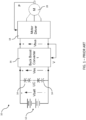
- all of the loads connected to the DC bus may be used quickly (e.g., within one or two seconds). It should be understood that if pre-charge circuit 122 and main contactor 120 were not present, a significant delay would be required before operating any of the capacitive loads in parallel with UC 104. The delay would correspond to the time required to charge UC 104.
- SCM 114 may be programmed with voltage thresholds to use in the determination of when to close and open pre-charge switches 126, 132 and main contactors 116, 120.
- UC 104 and the DC bus may maintain a non-zero voltage when the engine is shut down.
- the DC bus does not need to be deenergized (and therefore no such circuits are required) because the mild-hybrid system is a relatively low voltage system (e.g., 48 volts), posing no high voltage safety concerns.
- Battery 102 may simply be disconnected for safety by BMS 112 or SCM 114 opening main contactor 116.
- Architecture 100 is also configured to address voltage leakage of UC 104 over time. It is known that if UC 104 is left connected to the DC bus for an extended period of time, the voltage of UC 104 will slowly decrease due to leakage. Thus, architecture 100 permits SCM 114 to isolate UC 104 by opening switch 132 and main contactor 120 at engine shut down, thereby maintaining the operating voltage of UC 104 for a further extended period of time. Upon the next engine start-up, SCM 114 may connect UC 104 to the DC bus (by closing pre-charge switch 132 and then main contactor 120) before connecting battery 102 to the DC bus or at the same time as connecting battery 102.
- Architecture 100 also provides the ability to isolate UC 104 to reduce leakage and eliminate the need to pre-charge UC 104 as described herein. Other architectures provide this feature as shown, but at either a higher cost or higher complexity, or both. Architecture 100 also provides very rapid pre-charging of the DC bus, and high reliability for engine start-up, in part because of the ability to isolate UC 104.
- architecture 100 is designed to provide a low component count, in part by eliminating the need for a dedicated DC bus discharge circuit, which results in low cost and high reliability.
- a dedicated discharge circuit e.g., a resistor
- the embodiments of the present disclosure leverage the active discharge mechanisms supported by the power inverters and DC/DC converters that are already part of the overall mild-hybrid system.
Landscapes
- Engineering & Computer Science (AREA)
- Chemical & Material Sciences (AREA)
- Power Engineering (AREA)
- Mechanical Engineering (AREA)
- Combustion & Propulsion (AREA)
- Transportation (AREA)
- General Chemical & Material Sciences (AREA)
- Electrochemistry (AREA)
- Chemical Kinetics & Catalysis (AREA)
- General Engineering & Computer Science (AREA)
- Manufacturing & Machinery (AREA)
- Materials Engineering (AREA)
- Automation & Control Theory (AREA)
- Charge And Discharge Circuits For Batteries Or The Like (AREA)
- Secondary Cells (AREA)
- Electric Propulsion And Braking For Vehicles (AREA)
Applications Claiming Priority (3)
| Application Number | Priority Date | Filing Date | Title |
|---|---|---|---|
| US201962833823P | 2019-04-15 | 2019-04-15 | |
| PCT/US2020/014736 WO2020214225A1 (en) | 2019-04-15 | 2020-01-23 | A battery-ultracapacitor hybrid energy storage system architecture for mild-hybrid power systems |
| EP20791770.9A EP3956557B1 (de) | 2019-04-15 | 2020-01-23 | Batterie-ultrakondensator-hybridenergiespeichersystemarchitektur für mild-hybrid-leistungssysteme |
Related Parent Applications (2)
| Application Number | Title | Priority Date | Filing Date |
|---|---|---|---|
| EP20791770.9A Division-Into EP3956557B1 (de) | 2019-04-15 | 2020-01-23 | Batterie-ultrakondensator-hybridenergiespeichersystemarchitektur für mild-hybrid-leistungssysteme |
| EP20791770.9A Division EP3956557B1 (de) | 2019-04-15 | 2020-01-23 | Batterie-ultrakondensator-hybridenergiespeichersystemarchitektur für mild-hybrid-leistungssysteme |
Publications (2)
| Publication Number | Publication Date |
|---|---|
| EP4582280A2 true EP4582280A2 (de) | 2025-07-09 |
| EP4582280A3 EP4582280A3 (de) | 2025-10-08 |
Family
ID=72836965
Family Applications (2)
| Application Number | Title | Priority Date | Filing Date |
|---|---|---|---|
| EP20791770.9A Active EP3956557B1 (de) | 2019-04-15 | 2020-01-23 | Batterie-ultrakondensator-hybridenergiespeichersystemarchitektur für mild-hybrid-leistungssysteme |
| EP25178354.4A Pending EP4582280A3 (de) | 2019-04-15 | 2020-01-23 | Batterie-ultrakondensator-hybridenergiespeichersystemarchitektur für mild-hybridenergiesysteme |
Family Applications Before (1)
| Application Number | Title | Priority Date | Filing Date |
|---|---|---|---|
| EP20791770.9A Active EP3956557B1 (de) | 2019-04-15 | 2020-01-23 | Batterie-ultrakondensator-hybridenergiespeichersystemarchitektur für mild-hybrid-leistungssysteme |
Country Status (4)
| Country | Link |
|---|---|
| US (3) | US11967854B2 (de) |
| EP (2) | EP3956557B1 (de) |
| CN (2) | CN113631809B (de) |
| WO (1) | WO2020214225A1 (de) |
Families Citing this family (11)
| Publication number | Priority date | Publication date | Assignee | Title |
|---|---|---|---|---|
| CN113631809B (zh) | 2019-04-15 | 2023-10-27 | 康明斯公司 | 用于轻度混合动力系统的电池-超级电容器混合能量储存系统架构 |
| CN112820952B (zh) * | 2019-11-15 | 2025-02-11 | 通用汽车环球科技运作有限责任公司 | 电容器辅助的电池模块和系统 |
| CN113178934A (zh) * | 2021-06-03 | 2021-07-27 | 吉林大学 | 一种车用集成式低压储能电源系统及其控制方法 |
| WO2023129616A1 (en) | 2021-12-30 | 2023-07-06 | Sustainable Energy Technologies, Inc. | Supercapacitor to electrochemical hybrid system with a supercapacitor battery management capability |
| US12533968B2 (en) | 2021-12-30 | 2026-01-27 | Sustainable Energy Technologies, Inc. | Supercapacitor to electrochemical hybrid system with failsafe safety capability |
| WO2023129614A1 (en) | 2021-12-30 | 2023-07-06 | Sustainable Energy Technologies, Inc. | Supercapacitor to electrochemical hybrid system with smart self-discharge capability |
| US20240157826A1 (en) * | 2022-11-10 | 2024-05-16 | Doosan Bobcat North America, Inc. | Systems and methods for electrical power distribution in power machines |
| US20240170997A1 (en) * | 2022-11-23 | 2024-05-23 | Aptiv Technologies AG | Ultracapacitor module |
| CN116581857A (zh) * | 2023-03-21 | 2023-08-11 | 湖北师范大学 | 一种电池供电控制装置 |
| US20240322696A1 (en) * | 2023-03-21 | 2024-09-26 | Sensata Technologies, Inc. | Isolated solid-state active pre-charger |
| US20250070588A1 (en) * | 2023-08-22 | 2025-02-27 | Bae Systems Controls Inc. | Partial pre-charge of the high voltage system |
Family Cites Families (32)
| Publication number | Priority date | Publication date | Assignee | Title |
|---|---|---|---|---|
| US5723956A (en) * | 1996-05-28 | 1998-03-03 | General Electric Company | Low cost electronic ultracapacitor interface technique to provide load leveling of a battery for pulsed load or motor traction drive applications |
| JP3896258B2 (ja) | 2001-04-25 | 2007-03-22 | 株式会社日立製作所 | 自動車電源装置 |
| JP2004108226A (ja) * | 2002-09-18 | 2004-04-08 | Nissan Motor Co Ltd | エンジンのアイドルストップ装置およびアイドルストップ方法 |
| US7109686B2 (en) * | 2004-11-15 | 2006-09-19 | Ise Corporation | System and method for precharging and discharging a high power ultracapacitor pack |
| US7427450B2 (en) * | 2004-12-10 | 2008-09-23 | General Motors Corporation | Hybrid fuel cell system with battery capacitor energy storage system |
| JP4671336B2 (ja) | 2005-05-09 | 2011-04-13 | 株式会社小松製作所 | モータ駆動装置 |
| US7489048B2 (en) | 2006-01-09 | 2009-02-10 | General Electric Company | Energy storage system for electric or hybrid vehicle |
| US7806095B2 (en) * | 2007-08-31 | 2010-10-05 | Vanner, Inc. | Vehicle starting assist system |
| DE102007047713A1 (de) | 2007-10-05 | 2009-04-09 | Robert Bosch Gmbh | Verfahren zur Entladung des Hochspannungsnetzes |
| JP5104780B2 (ja) * | 2009-02-24 | 2012-12-19 | 株式会社デンソー | 車両用電源システム |
| US8154149B2 (en) | 2009-05-01 | 2012-04-10 | General Electric Company | Method and apparatus for charging a vehicle energy storage system |
| JP5381346B2 (ja) * | 2009-06-01 | 2014-01-08 | トヨタ自動車株式会社 | 電源装置および車両 |
| DE102010062249A1 (de) * | 2010-12-01 | 2012-06-21 | Zf Friedrichshafen Ag | Vorrichtung zur Verwendung in einem elektrischen Antriebssystem und Verfahren zum Betrieb einer solchen |
| WO2012125963A2 (en) * | 2011-03-16 | 2012-09-20 | Johnson Controls Technology Company | Energy source devices and systems having a battery and an ultracapacitor |
| US20130266826A1 (en) | 2012-03-13 | 2013-10-10 | Maxwell Technologies, Inc. | Ultracapacitor/battery combination and bus bar system |
| US9302912B2 (en) * | 2012-03-28 | 2016-04-05 | Mks Instruments, Inc. | Compact, configurable power supply for energizing ozone-producing cells |
| JP2015156254A (ja) | 2012-05-31 | 2015-08-27 | 三洋電機株式会社 | 電源装置とこの電源装置を備える電動車両 |
| JP5724959B2 (ja) * | 2012-07-09 | 2015-05-27 | トヨタ自動車株式会社 | 蓄電システム |
| FR2998108B1 (fr) | 2012-11-12 | 2014-12-19 | Accumulateurs Fixes | Systeme de pre-charge d'une capacite par une batterie |
| KR101988052B1 (ko) | 2012-12-24 | 2019-06-11 | 두산인프라코어 주식회사 | 하이브리드 건설기계용 전원 공급 장치 및 그 방법 |
| US9174525B2 (en) * | 2013-02-25 | 2015-11-03 | Fairfield Manufacturing Company, Inc. | Hybrid electric vehicle |
| DE102014200262B4 (de) | 2014-01-10 | 2025-03-13 | Robert Bosch Gmbh | Batteriesystem mit einer Batterie, die mit mindestens einem ihrer Hochvoltanschlüssen über ein Schütz verbindbar ist, und Verfahren zum Schalten eines solchen Schützes |
| US9573474B2 (en) * | 2014-03-06 | 2017-02-21 | Ford Global Technologies, Llc | Capacitor precharging and capacitance/resistance measurement in electric vehicle drive system |
| US20150295421A1 (en) | 2014-04-10 | 2015-10-15 | Ford Global Technologies, Llc | Active isolated circuit for precharging and discharging a high voltage bus |
| CA2977731A1 (en) | 2015-02-26 | 2016-09-01 | Gestima Solar S.L. | Device and method for managing the charging and discharging of ultracapacitors without control wiring |
| US10119514B2 (en) * | 2015-05-05 | 2018-11-06 | Ariel—University Research and Development Company Ltd. | Ultracapacitor-based power source |
| US10202958B2 (en) * | 2015-07-15 | 2019-02-12 | GM Global Technology Operations LLC | System and method for controlling ultra-capacitor charge and discharge in vehicles with auto start/stop systems |
| US9931949B2 (en) * | 2016-02-26 | 2018-04-03 | Ford Global Technologies, Llc | Fault detection in a multi-high voltage bus system |
| JP6916646B2 (ja) * | 2017-03-30 | 2021-08-11 | 本田技研工業株式会社 | エンジン発電機 |
| US10077752B1 (en) * | 2017-10-27 | 2018-09-18 | Hyundai Motor Company | Idle stop and go system and method controlling thereof |
| CN109228893A (zh) * | 2018-09-28 | 2019-01-18 | 肇庆理士电源技术有限公司 | 一种锂电池和超级电容混合储能的能源分配系统及其方法 |
| CN113631809B (zh) | 2019-04-15 | 2023-10-27 | 康明斯公司 | 用于轻度混合动力系统的电池-超级电容器混合能量储存系统架构 |
-
2020
- 2020-01-23 CN CN202080024466.9A patent/CN113631809B/zh active Active
- 2020-01-23 CN CN202311312393.5A patent/CN117365806A/zh active Pending
- 2020-01-23 EP EP20791770.9A patent/EP3956557B1/de active Active
- 2020-01-23 EP EP25178354.4A patent/EP4582280A3/de active Pending
- 2020-01-23 US US17/433,116 patent/US11967854B2/en active Active
- 2020-01-23 WO PCT/US2020/014736 patent/WO2020214225A1/en not_active Ceased
-
2024
- 2024-02-27 US US18/589,120 patent/US12244171B2/en active Active
-
2025
- 2025-01-28 US US19/039,654 patent/US20250192601A1/en active Pending
Also Published As
| Publication number | Publication date |
|---|---|
| US20240283280A1 (en) | 2024-08-22 |
| US20220190629A1 (en) | 2022-06-16 |
| CN117365806A (zh) | 2024-01-09 |
| US11967854B2 (en) | 2024-04-23 |
| EP3956557A4 (de) | 2023-01-11 |
| EP3956557B1 (de) | 2025-07-02 |
| WO2020214225A1 (en) | 2020-10-22 |
| CN113631809A (zh) | 2021-11-09 |
| US20250192601A1 (en) | 2025-06-12 |
| US12244171B2 (en) | 2025-03-04 |
| EP3956557A1 (de) | 2022-02-23 |
| EP4582280A3 (de) | 2025-10-08 |
| CN113631809B (zh) | 2023-10-27 |
Similar Documents
| Publication | Publication Date | Title |
|---|---|---|
| US12244171B2 (en) | Battery-ultracapacitor hybrid energy storage system architecture for mild-hybrid power systems | |
| EP3536536B1 (de) | Fahrzeugspannungsversorgungssystem und steuerverfahren | |
| US7768237B2 (en) | Simplified automatic discharge function for vehicles | |
| CN101407180B (zh) | 用于交通工具系统的双储能设备 | |
| CN105324274B (zh) | 车辆用电源系统 | |
| CN102084574A (zh) | 用于车载电网的电压稳定化的电路 | |
| CN104737412B (zh) | 电源管理系统及电源管理方法 | |
| US9789769B2 (en) | Power supply device for vehicles | |
| US20120286569A1 (en) | Circuit system for a vehicle electrical system | |
| JP6174876B2 (ja) | 2電源負荷駆動システム及び燃料電池自動車 | |
| US10333179B2 (en) | Method for operating a battery system, battery system and motor vehicle | |
| EP3553907A1 (de) | Energieversorgungsgerät | |
| KR20220151962A (ko) | 차량 비상 시동 장치, 그 제어 방법, 및 상기 방법을 실행시키기 위한 컴퓨터 판독 가능한 프로그램을 기록한 기록 매체 | |
| CN111123089B (zh) | 继电器检测电路和装置 | |
| JP4636313B2 (ja) | 車両用制御装置 | |
| CN114475489A (zh) | 汽车的电源系统及汽车、汽车的电源系统的控制方法 | |
| KR20140068556A (ko) | 전기자동차용 직류 변환장치의 제어방법 | |
| KR101034084B1 (ko) | 하이브리드 차량의 2차 소손 방지 장치 및 방지 방법 | |
| CN118560279A (zh) | 一种取电系统及其控制方法、车辆和存储介质 | |
| CN214874327U (zh) | 高压电气系统和车辆 | |
| CN118254702B (zh) | 一种车辆控制的方法、装置、车辆和存储介质 | |
| CN223533357U (zh) | 新能源汽车高压控制电路及车辆 | |
| KR20250159238A (ko) | 전기 또는 하이브리드 차량의 소비처에 전력을 공급하기 위한 시스템 및 차량의 전력 공급을 관리하는 방법 | |
| CN119928820A (zh) | 车辆控制方法、装置、车辆和计算机可读存储介质 | |
| KR20260023777A (ko) | 통신 불량 상태에서 ldc 컨버터 동작 유지 방법 |
Legal Events
| Date | Code | Title | Description |
|---|---|---|---|
| PUAI | Public reference made under article 153(3) epc to a published international application that has entered the european phase |
Free format text: ORIGINAL CODE: 0009012 |
|
| STAA | Information on the status of an ep patent application or granted ep patent |
Free format text: STATUS: THE APPLICATION HAS BEEN PUBLISHED |
|
| AC | Divisional application: reference to earlier application |
Ref document number: 3956557 Country of ref document: EP Kind code of ref document: P |
|
| AK | Designated contracting states |
Kind code of ref document: A2 Designated state(s): AL AT BE BG CH CY CZ DE DK EE ES FI FR GB GR HR HU IE IS IT LI LT LU LV MC MK MT NL NO PL PT RO RS SE SI SK SM TR |
|
| RIN1 | Information on inventor provided before grant (corrected) |
Inventor name: VARIGONDA, SUBBARAO Inventor name: LEONARSKI, JAROSLAW Inventor name: ADEMANE, HARSHA RAVINDRA |
|
| REG | Reference to a national code |
Ref country code: DE Ref legal event code: R079 Free format text: PREVIOUS MAIN CLASS: B60K0006280000 Ipc: F02N0011080000 |
|
| PUAL | Search report despatched |
Free format text: ORIGINAL CODE: 0009013 |
|
| AK | Designated contracting states |
Kind code of ref document: A3 Designated state(s): AL AT BE BG CH CY CZ DE DK EE ES FI FR GB GR HR HU IE IS IT LI LT LU LV MC MK MT NL NO PL PT RO RS SE SI SK SM TR |
|
| RIC1 | Information provided on ipc code assigned before grant |
Ipc: F02N 11/08 20060101AFI20250904BHEP Ipc: H02J 7/34 20060101ALI20250904BHEP Ipc: H01M 16/00 20060101ALI20250904BHEP Ipc: B60W 20/00 20160101ALI20250904BHEP Ipc: H02J 7/14 20060101ALI20250904BHEP Ipc: H01M 10/0525 20100101ALI20250904BHEP Ipc: B60K 6/28 20071001ALI20250904BHEP Ipc: H01M 10/48 20060101ALN20250904BHEP Ipc: H01M 10/44 20060101ALN20250904BHEP |
|
| STAA | Information on the status of an ep patent application or granted ep patent |
Free format text: STATUS: REQUEST FOR EXAMINATION WAS MADE |