EP4582288A1 - Capteur de courant à double sortie, système de protection contre les courts-circuits comprenant un capteur de courant à double sortie et procédé associé - Google Patents
Capteur de courant à double sortie, système de protection contre les courts-circuits comprenant un capteur de courant à double sortie et procédé associé Download PDFInfo
- Publication number
- EP4582288A1 EP4582288A1 EP24223127.2A EP24223127A EP4582288A1 EP 4582288 A1 EP4582288 A1 EP 4582288A1 EP 24223127 A EP24223127 A EP 24223127A EP 4582288 A1 EP4582288 A1 EP 4582288A1
- Authority
- EP
- European Patent Office
- Prior art keywords
- current
- detected
- output
- comparison
- current sensor
- Prior art date
- Legal status (The legal status is an assumption and is not a legal conclusion. Google has not performed a legal analysis and makes no representation as to the accuracy of the status listed.)
- Pending
Links
Images


Classifications
-
- G—PHYSICS
- G01—MEASURING; TESTING
- G01R—MEASURING ELECTRIC VARIABLES; MEASURING MAGNETIC VARIABLES
- G01R19/00—Arrangements for measuring currents or voltages or for indicating presence or sign thereof
- G01R19/165—Indicating that current or voltage is either above or below a predetermined value or within or outside a predetermined range of values
- G01R19/16528—Indicating that current or voltage is either above or below a predetermined value or within or outside a predetermined range of values using digital techniques or performing arithmetic operations
-
- H—ELECTRICITY
- H02—GENERATION; CONVERSION OR DISTRIBUTION OF ELECTRIC POWER
- H02H—EMERGENCY PROTECTIVE CIRCUIT ARRANGEMENTS
- H02H3/00—Emergency protective circuit arrangements for automatic disconnection directly responsive to an undesired change from normal electric working condition with or without subsequent reconnection ; integrated protection
- H02H3/02—Details
- H02H3/05—Details with means for increasing reliability, e.g. redundancy arrangements
-
- G—PHYSICS
- G01—MEASURING; TESTING
- G01R—MEASURING ELECTRIC VARIABLES; MEASURING MAGNETIC VARIABLES
- G01R19/00—Arrangements for measuring currents or voltages or for indicating presence or sign thereof
- G01R19/0092—Measuring current only
-
- B—PERFORMING OPERATIONS; TRANSPORTING
- B60—VEHICLES IN GENERAL
- B60L—PROPULSION OF ELECTRICALLY-PROPELLED VEHICLES; SUPPLYING ELECTRIC POWER FOR AUXILIARY EQUIPMENT OF ELECTRICALLY-PROPELLED VEHICLES; ELECTRODYNAMIC BRAKE SYSTEMS FOR VEHICLES IN GENERAL; MAGNETIC SUSPENSION OR LEVITATION FOR VEHICLES; MONITORING OPERATING VARIABLES OF ELECTRICALLY-PROPELLED VEHICLES; ELECTRIC SAFETY DEVICES FOR ELECTRICALLY-PROPELLED VEHICLES
- B60L3/00—Electric devices on electrically-propelled vehicles for safety purposes; Monitoring operating variables, e.g. speed, deceleration or energy consumption
-
- B—PERFORMING OPERATIONS; TRANSPORTING
- B60—VEHICLES IN GENERAL
- B60L—PROPULSION OF ELECTRICALLY-PROPELLED VEHICLES; SUPPLYING ELECTRIC POWER FOR AUXILIARY EQUIPMENT OF ELECTRICALLY-PROPELLED VEHICLES; ELECTRODYNAMIC BRAKE SYSTEMS FOR VEHICLES IN GENERAL; MAGNETIC SUSPENSION OR LEVITATION FOR VEHICLES; MONITORING OPERATING VARIABLES OF ELECTRICALLY-PROPELLED VEHICLES; ELECTRIC SAFETY DEVICES FOR ELECTRICALLY-PROPELLED VEHICLES
- B60L3/00—Electric devices on electrically-propelled vehicles for safety purposes; Monitoring operating variables, e.g. speed, deceleration or energy consumption
- B60L3/0023—Detecting, eliminating, remedying or compensating for drive train abnormalities, e.g. failures within the drive train
- B60L3/0046—Detecting, eliminating, remedying or compensating for drive train abnormalities, e.g. failures within the drive train relating to electric energy storage systems, e.g. batteries or capacitors
-
- B—PERFORMING OPERATIONS; TRANSPORTING
- B60—VEHICLES IN GENERAL
- B60L—PROPULSION OF ELECTRICALLY-PROPELLED VEHICLES; SUPPLYING ELECTRIC POWER FOR AUXILIARY EQUIPMENT OF ELECTRICALLY-PROPELLED VEHICLES; ELECTRODYNAMIC BRAKE SYSTEMS FOR VEHICLES IN GENERAL; MAGNETIC SUSPENSION OR LEVITATION FOR VEHICLES; MONITORING OPERATING VARIABLES OF ELECTRICALLY-PROPELLED VEHICLES; ELECTRIC SAFETY DEVICES FOR ELECTRICALLY-PROPELLED VEHICLES
- B60L3/00—Electric devices on electrically-propelled vehicles for safety purposes; Monitoring operating variables, e.g. speed, deceleration or energy consumption
- B60L3/0023—Detecting, eliminating, remedying or compensating for drive train abnormalities, e.g. failures within the drive train
- B60L3/0069—Detecting, eliminating, remedying or compensating for drive train abnormalities, e.g. failures within the drive train relating to the isolation, e.g. ground fault or leak current
-
- B—PERFORMING OPERATIONS; TRANSPORTING
- B60—VEHICLES IN GENERAL
- B60L—PROPULSION OF ELECTRICALLY-PROPELLED VEHICLES; SUPPLYING ELECTRIC POWER FOR AUXILIARY EQUIPMENT OF ELECTRICALLY-PROPELLED VEHICLES; ELECTRODYNAMIC BRAKE SYSTEMS FOR VEHICLES IN GENERAL; MAGNETIC SUSPENSION OR LEVITATION FOR VEHICLES; MONITORING OPERATING VARIABLES OF ELECTRICALLY-PROPELLED VEHICLES; ELECTRIC SAFETY DEVICES FOR ELECTRICALLY-PROPELLED VEHICLES
- B60L3/00—Electric devices on electrically-propelled vehicles for safety purposes; Monitoring operating variables, e.g. speed, deceleration or energy consumption
- B60L3/04—Cutting off the power supply under fault conditions
-
- G—PHYSICS
- G01—MEASURING; TESTING
- G01R—MEASURING ELECTRIC VARIABLES; MEASURING MAGNETIC VARIABLES
- G01R1/00—Details of instruments or arrangements of the types included in groups G01R5/00 - G01R13/00 and G01R31/00
- G01R1/30—Structural combination of electric measuring instruments with basic electronic circuits, e.g. with amplifier
-
- G—PHYSICS
- G01—MEASURING; TESTING
- G01R—MEASURING ELECTRIC VARIABLES; MEASURING MAGNETIC VARIABLES
- G01R13/00—Arrangements for displaying electric variables or waveforms
- G01R13/02—Arrangements for displaying electric variables or waveforms for displaying measured electric variables in digital form
-
- G—PHYSICS
- G01—MEASURING; TESTING
- G01R—MEASURING ELECTRIC VARIABLES; MEASURING MAGNETIC VARIABLES
- G01R19/00—Arrangements for measuring currents or voltages or for indicating presence or sign thereof
- G01R19/10—Measuring sum, difference or ratio
-
- G—PHYSICS
- G01—MEASURING; TESTING
- G01R—MEASURING ELECTRIC VARIABLES; MEASURING MAGNETIC VARIABLES
- G01R19/00—Arrangements for measuring currents or voltages or for indicating presence or sign thereof
- G01R19/165—Indicating that current or voltage is either above or below a predetermined value or within or outside a predetermined range of values
- G01R19/16533—Indicating that current or voltage is either above or below a predetermined value or within or outside a predetermined range of values characterised by the application
- G01R19/16538—Indicating that current or voltage is either above or below a predetermined value or within or outside a predetermined range of values characterised by the application in AC or DC supplies
- G01R19/16542—Indicating that current or voltage is either above or below a predetermined value or within or outside a predetermined range of values characterised by the application in AC or DC supplies for batteries
-
- G—PHYSICS
- G01—MEASURING; TESTING
- G01R—MEASURING ELECTRIC VARIABLES; MEASURING MAGNETIC VARIABLES
- G01R19/00—Arrangements for measuring currents or voltages or for indicating presence or sign thereof
- G01R19/165—Indicating that current or voltage is either above or below a predetermined value or within or outside a predetermined range of values
- G01R19/16566—Circuits and arrangements for comparing voltage or current with one or several thresholds and for indicating the result not covered by subgroups G01R19/16504, G01R19/16528, G01R19/16533
- G01R19/16571—Circuits and arrangements for comparing voltage or current with one or several thresholds and for indicating the result not covered by subgroups G01R19/16504, G01R19/16528, G01R19/16533 comparing AC or DC current with one threshold, e.g. load current, over-current, surge current or fault current
-
- G—PHYSICS
- G01—MEASURING; TESTING
- G01R—MEASURING ELECTRIC VARIABLES; MEASURING MAGNETIC VARIABLES
- G01R19/00—Arrangements for measuring currents or voltages or for indicating presence or sign thereof
- G01R19/25—Arrangements for measuring currents or voltages or for indicating presence or sign thereof using digital measurement techniques
-
- H—ELECTRICITY
- H01—ELECTRIC ELEMENTS
- H01H—ELECTRIC SWITCHES; RELAYS; SELECTORS; EMERGENCY PROTECTIVE DEVICES
- H01H37/00—Thermally-actuated switches
- H01H37/74—Switches in which only the opening movement or only the closing movement of a contact is effected by heating or cooling
- H01H37/76—Contact member actuated by melting of fusible material, actuated due to burning of combustible material or due to explosion of explosive material
-
- H—ELECTRICITY
- H01—ELECTRIC ELEMENTS
- H01M—PROCESSES OR MEANS, e.g. BATTERIES, FOR THE DIRECT CONVERSION OF CHEMICAL ENERGY INTO ELECTRICAL ENERGY
- H01M50/00—Constructional details or processes of manufacture of the non-active parts of electrochemical cells other than fuel cells, e.g. hybrid cells
- H01M50/50—Current conducting connections for cells or batteries
- H01M50/572—Means for preventing undesired use or discharge
- H01M50/574—Devices or arrangements for the interruption of current
- H01M50/583—Devices or arrangements for the interruption of current in response to current, e.g. fuses
-
- H—ELECTRICITY
- H02—GENERATION; CONVERSION OR DISTRIBUTION OF ELECTRIC POWER
- H02H—EMERGENCY PROTECTIVE CIRCUIT ARRANGEMENTS
- H02H1/00—Details of emergency protective circuit arrangements
- H02H1/0007—Details of emergency protective circuit arrangements concerning the detecting means
-
- H—ELECTRICITY
- H02—GENERATION; CONVERSION OR DISTRIBUTION OF ELECTRIC POWER
- H02H—EMERGENCY PROTECTIVE CIRCUIT ARRANGEMENTS
- H02H3/00—Emergency protective circuit arrangements for automatic disconnection directly responsive to an undesired change from normal electric working condition with or without subsequent reconnection ; integrated protection
- H02H3/08—Emergency protective circuit arrangements for automatic disconnection directly responsive to an undesired change from normal electric working condition with or without subsequent reconnection ; integrated protection responsive to excess current
-
- H—ELECTRICITY
- H02—GENERATION; CONVERSION OR DISTRIBUTION OF ELECTRIC POWER
- H02H—EMERGENCY PROTECTIVE CIRCUIT ARRANGEMENTS
- H02H3/00—Emergency protective circuit arrangements for automatic disconnection directly responsive to an undesired change from normal electric working condition with or without subsequent reconnection ; integrated protection
- H02H3/08—Emergency protective circuit arrangements for automatic disconnection directly responsive to an undesired change from normal electric working condition with or without subsequent reconnection ; integrated protection responsive to excess current
- H02H3/087—Emergency protective circuit arrangements for automatic disconnection directly responsive to an undesired change from normal electric working condition with or without subsequent reconnection ; integrated protection responsive to excess current for DC applications
-
- H—ELECTRICITY
- H02—GENERATION; CONVERSION OR DISTRIBUTION OF ELECTRIC POWER
- H02H—EMERGENCY PROTECTIVE CIRCUIT ARRANGEMENTS
- H02H7/00—Emergency protective circuit arrangements specially adapted for specific types of electric machines or apparatus or for sectionalised protection of cable or line systems, and effecting automatic switching in the event of an undesired change from normal working conditions
- H02H7/18—Emergency protective circuit arrangements specially adapted for specific types of electric machines or apparatus or for sectionalised protection of cable or line systems, and effecting automatic switching in the event of an undesired change from normal working conditions for batteries; for accumulators
-
- B—PERFORMING OPERATIONS; TRANSPORTING
- B60—VEHICLES IN GENERAL
- B60L—PROPULSION OF ELECTRICALLY-PROPELLED VEHICLES; SUPPLYING ELECTRIC POWER FOR AUXILIARY EQUIPMENT OF ELECTRICALLY-PROPELLED VEHICLES; ELECTRODYNAMIC BRAKE SYSTEMS FOR VEHICLES IN GENERAL; MAGNETIC SUSPENSION OR LEVITATION FOR VEHICLES; MONITORING OPERATING VARIABLES OF ELECTRICALLY-PROPELLED VEHICLES; ELECTRIC SAFETY DEVICES FOR ELECTRICALLY-PROPELLED VEHICLES
- B60L2240/00—Control parameters of input or output; Target parameters
- B60L2240/40—Drive Train control parameters
- B60L2240/54—Drive Train control parameters related to batteries
- B60L2240/549—Current
Definitions
- Short circuit protection systems are important in electrical systems. For example, such short circuit protection systems are used in electric vehicles to protect the motor and battery from short circuits which can expose sensitive components to very high currents.
- a system for providing short circuit protection comprises a dual-output current sensor.
- the dual-output current sensor comprises a current sensing element to detect a current, a current comparison circuity to determine if the detected current exceeds a predetermined threshold current, a first output channel to output an indication of the detected current from the current sensor, a drive circuit to produce an amplified output of the current comparison circuity, and a second output channel to output the amplified output of the current comparison circuity from the current sensor.
- the current sensing element outputs a voltage that is proportional to the detected current
- the current comparison circuity comprises an analog voltage comparison circuitry that compares the voltage that is proportional to the detected current to a reference voltage that corresponds to the predetermined threshold current.
- the current sensing element outputs a voltage that is proportional to the detected current
- the current comparison circuity comprises an analog to digital controller (ADC) and a controller
- ADC analog to digital controller
- the ADC receives the voltage that is proportional to the detected current and converts the voltage that is proportional to the detected current to a digital value of the detected current
- the controller receives the digital value of the detected current and compares the digital value of the detected current to the predetermined threshold current.
- the system further comprises a battery management system, an electric busbar carrying the detected current, and a normally closed pyrotechnic switch connected inline with the electric busbar.
- the first output channel outputs the indication of the detected current to a battery management system of an electric vehicle, and the second output channel outputs the amplified output of the current comparison circuity to a pyrotechnic switch to cause the pyrotechnic switch to open and interrupt the detected current on the electric busbar.
- the current sensor receives a command from the battery management system to actuate the pyrotechnic switch and the second output channel outputs the amplified output of the current comparison circuity to the pyrotechnic switch in response to the current sensor receiving the command from the battery management system to actuate the pyrotechnic switch.
- a system for providing short circuit protection in an electric vehicle comprises a battery management system, an electric busbar, a normally closed pyrotechnic switch connected inline with the electric busbar, and a dual-output current sensor to detect a current on the electric busbar.
- the current sensor comprises a current sensing element to detect the current on the electric busbar, a current comparison circuity to determine if the detected current exceeds a predetermined threshold current, a first output channel to output an indication of the detected current from the current sensor to the battery management system, a drive circuit to produce an amplified output of the current comparison circuity, and a second output channel to output the amplified output of the current comparison circuity from the current sensor to the pyrotechnic switch to cause the pyrotechnic switch to open and interrupt the current on the electric busbar.
- a method of providing short circuit protection in an electric vehicle comprises connecting a dual-output current sensor to an electric busbar of the electric vehicle; detecting, by a current sensing element of the current sensor, the current on the electric busbar; determining, by a current comparison circuitry of the current sensor, if the detected current exceeds a predetermined threshold current; outputting, by a first output channel of the current sensor to a battery management system of the electric vehicle, an indication of the detected current; producing, by a drive circuit of the current sensor, an amplified output of the current comparison circuity; and outputting, by a second output channel of the current sensor to a pyrotechnic switch of the electric vehicle, the amplified output of the current comparison circuity to cause the pyrotechnic switch to open and interrupt the current on the electric busbar.
- the term "comprising” means including but not limited to and should be interpreted in the manner it is typically used in the patent context. Use of broader terms such as comprises, includes, and having should be understood to provide support for narrower terms such as consisting of, consisting essentially of, and comprised substantially of.
- component or feature may,” “can,” “could,” “should,” “would,” “preferably,” “possibly,” “typically,” “optionally,” “for example,” “as an example,” “in some examples,” “often,” or “might” (or other such language) be included or have a characteristic, that specific component or feature is not required to be included or to have the characteristic. Such component or feature may be optionally included in some examples, or it may be excluded.
- component may refer to an article, a device, or an apparatus that may comprise one or more surfaces, portions, layers and/or elements.
- an example component may comprise one or more substrates that may provide underlying layer(s) for the component and may comprise one or more elements that may form part of and/or are disposed on top of the substrate.
- element may refer to an article, a device, or an apparatus that may provide one or more functionalities.
- sensing element may refer to one or more components, integrated circuits, and the like within a sensing device that interacts with the environment, detects the input to be detected (e.g., electric current), and provides an output (e.g., voltage) to another component in the sensing device to be interpreted.
- the sensing circuitry may comprise an open-loop Hall-effect sensor, a closed-loop Hall-effect sensor, a fluxgate sensor, or any suitable sensing element.
- various examples of the present disclosure may be provided.
- various examples of the present disclosure may provide example dual output current sensors, systems for short circuit protection, and methods for short circuit protection.
- an example dual output current sensor is connected to a busbar of an electric vehicle to measure the primary current on the busbar.
- a first output of an example dual output current sensor provides an indication of the measured primary current to a battery management system (BMS) of an electric vehicle.
- BMS battery management system
- a second output of an example dual output current sensor provides a control signal to a pyrotechnic switch of an electric vehicle when the measured primary current exceeds a predetermined threshold.
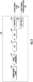
- the sensing element 205 may comprise a magnetic field current sensor magnetically coupled to a conductor (i.e., a busbar) and configured to generate a magnetic field signal having a magnitude responsive to a current flowing through the conductor.
- the sensing element 205 may comprise a shunt interface having first and second input terminals electrically coupled to ends of a shunt disposed along a conductor (i.e., busbar) and configured to generate a shunt signal having a magnitude responsive to the current flowing through the conductor.
- the sensing element 205 may comprise an open-loop Hall-effect sensor, a closed-loop Hall-effect sensor, a fluxgate sensor, or any suitable current sensing element.
- the sensing element 205 produces an analog voltage that is proportional to the primary current flowing through the busbar.
- the signal adjustment element 210 comprises an amplifier to amplify the voltage from the current sensing element 205. In some embodiments, the signal adjustment element is not needed.
- the MCU 220 determines that the measured current exceeds the predetermined threshold, the MCU 220 outputs an overcurrent signal (e.g., a pulse width modulated (PWM signal) to the drive circuit 230.
- the drive circuit 230 amplifies the overcurrent signal from the MCU 220 and outputs the amplified signal via the second output channel 240 to a pyrotechnic switch, thereby causing the pyrotechnic switch to actuate.
- the drive circuit functionality is provided by a Bosch CG912 four channel pyrotechnic fuse driver.
- the decision to actuate the pyrotechnic switch is not made within the current sensor (such as within the MCU), but rather the decision to actuate the pyrotechnic switch is made within the BMS.
- the BMS if the BMS makes a decision to actuate the pyrotechnic switch, the BMS sends a control command to the current sensor, the control command is received by the current sensor via the transceiver 225, and a control signal is sent to the pyrotechnic switch from the current sensor via the second output channel 240.
- the BMS makes a decision to actuate the pyrotechnic switch, the BMS sends a control command directly to the pyrotechnic switch.
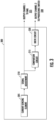
- a dual output current sensor 300 comprises a current sensing element 305, a signal adjustment element 310, a comparison circuit 315, and a drive circuit 320.
- the current sensor 300 has two outputs: a first output channel 325 that provides an indication of the measured primary current to a BMS of an electric vehicle and a second output channel 330 that provides a control signal to a pyrotechnic switch to cause the pyrotechnic switch to actuate (i.e., open) when the measured primary current exceeds the predetermined threshold.
- the sensing element 305 may comprise an open-loop Hall-effect sensor, a closed-loop Hall-effect sensor, a fluxgate sensor, or any suitable current sensing element.
- the sensing element 305 produces an analog voltage that is proportional to the primary current flowing through the busbar.
- the signal adjustment element 310 comprises an amplifier to amplify the voltage from the current sensing element 305. In some embodiments, the signal adjustment element is not needed.
- the analog voltage from the current sensing element 305 (which may have been amplified by the signal adjustment element 310, if present) is output via the first output channel 325 to a BMS.
- the representation of the measured current is proportional to the primary current.
- the analog voltage from the current sensing element 305 (which may have been amplified by the signal adjustment element 310, if present) is provided to the comparison circuit 315.
- the comparison circuit 315 compares the analog voltage from the current sensing element 305 to a reference voltage that is selected to be equal to what the analog voltage from the current sensing element 305 will be if the primary current is equal to the threshold current. In various embodiments, if the analog voltage from the current sensing element 305 is higher than the reference voltage, the comparison circuit 315 will output a positive voltage to the drive circuit 320.
- the drive circuit 320 amplifies the positive output voltage from the comparison circuit 315 and outputs the amplified signal via the second output channel 330 to a pyrotechnic switch, thereby causing the pyrotechnic switch to actuate.
- Dual output current sensors of embodiments of the present disclosure may use any suitable drive circuit that is capable of receiving a signal from an MCU (such as MCU 220) or a comparison circuit (such as comparison circuit 315) and amplifying the signal to the desired level needed to actuate a pyrotechnic switch.
- MCU such as MCU 220
- comparison circuit such as comparison circuit 315
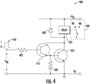
- FIG. 4 a circuit diagram of an example drive circuit that may be used in the example dual output current sensor of FIG. 2 or the example dual output current sensor of FIG. 3 is illustrated, in accordance with various embodiments of the disclosure. As seen in FIG.
- the drive circuit 400 comprises a first resistor 405, a first transistor 415 (such as an NPN low power, silicon planar epitaxial transistor), a second resistor 420, a second transistor 425 (such as an NPN bipolar junction transistor), a diode 430, and a relay 435.
- a first resistor 405 such as an NPN low power, silicon planar epitaxial transistor
- a second resistor 420 such as an NPN bipolar junction transistor
- diode 430 such as an NPN bipolar junction transistor
- the cathode of the diode 430 and the other end of the relay 435 are connected to the supply voltage (Vcc).
- the relay 435 is connected to and drives actuation of the pyrotechnic switch 440.
- the drive circuit 400 receives a positive input signal 410 (for example, from MCU 220 or comparison circuit 315), which indicates an overcurrent has been detected, the input signal is amplified and actuates the relay 435 which actuates the pyrotechnic switch 440.
- Dual output current sensors of embodiments of the present disclosure may use any suitable comparison circuit that is capable of receiving an analog voltage from a current sensing element (such as current sensing element 305), comparing that analog voltage to a reference voltage that is equal to what the analog voltage from the current sensing element will be if the primary current is equal to the threshold current, and, if the analog voltage from the current sensing element is higher than the reference voltage, outputting a positive voltage to a drive circuit (such as drive circuit 320).
- a drive circuit such as drive circuit 320
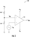
- the comparison circuit 500 comprises a first resistor 505 and a second resistor 510 connected in series between the supply voltage (Vcc) and ground and an op-amp 515.
- the negative input terminal of the op-amp 515 is connected between the first resistor 505 and the second resistor 510 and the positive input terminal of the op-amp 515 is connected to the analog voltage (Vin) from the current sensing element.
- the op-amp 515 is connected to a positive supply voltage (Vcc) and a negative supply voltage (V EE ).
- the output of the op-amp 515 is Vout.
- the value the first resistor 505 and the value of the second resistor 510 are selected such that the reference voltage V REF is equal to what the analog voltage from the current sensing element will be if the primary current is equal to the predetermined threshold current.
- the output (Vout) of the op-amp 515 is positive. In various embodiments, this positive output is amplified by a drive circuit and actuates a pyrotechnic switch.
- the MCU 220 may be configured to execute instructions stored in memory circuitry (not illustrated) or otherwise accessible to the processor. Alternatively, or additionally, the MCU 220 may be configured to execute hard-coded functionality. As such, whether configured by hardware or software methods, or by a combination thereof, MCU 220 may represent an entity (e.g., physically embodied in circuitry) capable of performing operations according to embodiments of the present disclosure while configured accordingly. Alternatively, or additionally, MCU 220 may be embodied as an executor of software instructions, and the instructions may specifically configure the MCU 220 to perform the various algorithms embodied in one or more operations described herein when such instructions are executed. In some embodiments, the MCU 220 includes hardware, software, firmware, and/or a combination thereof that performs one or more operations described herein.
- two or more of the sets of circuitries are combinable. Alternatively, or additionally, one or more of the sets of circuitry perform some or all of the operations and/or functionality described herein as being associated with another circuitry. In some embodiments, two or more of the sets of circuitry are combined into a single module embodied in hardware, software, firmware, and/or a combination thereof.
- an example current sensor 100 in accordance with the present disclosure may be in other forms.
- an example current sensor 100 may comprise one or more additional and/or alternative elements, and/or may be structured differently than that illustrated in FIGS. 2 and 3 .
- FIG. 6 provides a flowchart illustrating example steps, processes, procedures, and/or operations in accordance with various embodiments of the present disclosure.
- Various methods described herein, including, for example, methods as shown in FIG. 6 may provide various technical benefits and improvements.
- the example method comprises a method for providing short circuit protection using a dual output current sensor.
- a dual output current sensor (such as, but not limited to, the dual output current sensor 200 described above in connection with FIG. 2 or the dual output current sensor 300 described above in connection with FIG. 3 ) detects a primary current on an electric busbar.
- a dual output current sensor (such as, but not limited to, the dual output current sensor 200 described above in connection with FIG. 2 or the dual output current sensor 300 described above in connection with FIG. 3 ) outputs an indication of the detected current to a battery management system via a first output channel.
- a dual output current sensor determines if the detected current exceeds a predetermined threshold current.
- a dual output current sensor (such as, but not limited to, the dual output current sensor 200 described above in connection with FIG. 2 or the dual output current sensor 300 described above in connection with FIG. 3 ) outputs an overcurrent error to the battery management system via the first output channel and outputs a control signal to a pyrotechnic switch via a second output channel to actuate the pyrotechnic switch.
- the decision to actuate the pyrotechnic switch is made within the BMS and, if the BMS makes a decision to actuate the pyrotechnic switch, the BMS sends a control command to the current sensor and the current sensor receives the control command from the BMS (such as, but not limited to, via the transceiver 225 of the dual output current sensor 200 described above in connection with FIG. 2 ).
- This portion of step/operation 625 is in brackets to indicate that it is optional.
- the method 600 repeats steps/operations 605-620 until an overcurrent is detected and the pyrotechnic switch is actuated.
- Operations and processes described herein support combinations of means for performing the specified functions and combinations of operations for performing the specified functions. It will be understood that one or more operations, and combinations of operations, may be implemented by special purpose hardware-based computer systems which perform the specified functions, or combinations of special purpose hardware and computer instructions.
- certain ones of the operations herein may be modified or further amplified as described below. Moreover, in some embodiments additional optional operations may also be included. It should be appreciated that each of the modifications, optional additions or amplifications described herein may be included with the operations herein either alone or in combination with any others among the features described herein.
- systems, subsystems, apparatuses, techniques, and methods described and illustrated in the various embodiments as discrete or separate may be combined or integrated with other systems, modules, techniques, or methods without departing from the scope of the present disclosure.
- Other devices or components shown or discussed as coupled to, or in communication with, each other may be indirectly coupled through some intermediate device or component, whether electrically, mechanically, or otherwise.
- Other examples of changes, substitutions, and alterations are ascertainable by one skilled in the art and could be made without departing from the scope disclosed herein.
Landscapes
- Engineering & Computer Science (AREA)
- Physics & Mathematics (AREA)
- General Physics & Mathematics (AREA)
- Power Engineering (AREA)
- Mechanical Engineering (AREA)
- Life Sciences & Earth Sciences (AREA)
- Sustainable Development (AREA)
- Sustainable Energy (AREA)
- Transportation (AREA)
- Chemical & Material Sciences (AREA)
- Chemical Kinetics & Catalysis (AREA)
- Electrochemistry (AREA)
- General Chemical & Material Sciences (AREA)
- Combustion & Propulsion (AREA)
- Emergency Protection Circuit Devices (AREA)
- Protection Of Static Devices (AREA)
- Charge And Discharge Circuits For Batteries Or The Like (AREA)
Applications Claiming Priority (1)
| Application Number | Priority Date | Filing Date | Title |
|---|---|---|---|
| CN202410021372.6A CN120280855A (zh) | 2024-01-05 | 2024-01-05 | 双输出电流传感器、提供短路保护的系统以及关联方法 |
Publications (1)
| Publication Number | Publication Date |
|---|---|
| EP4582288A1 true EP4582288A1 (fr) | 2025-07-09 |
Family
ID=94116752
Family Applications (1)
| Application Number | Title | Priority Date | Filing Date |
|---|---|---|---|
| EP24223127.2A Pending EP4582288A1 (fr) | 2024-01-05 | 2024-12-23 | Capteur de courant à double sortie, système de protection contre les courts-circuits comprenant un capteur de courant à double sortie et procédé associé |
Country Status (5)
| Country | Link |
|---|---|
| US (1) | US20250224431A1 (fr) |
| EP (1) | EP4582288A1 (fr) |
| JP (1) | JP7842188B2 (fr) |
| KR (1) | KR20250107726A (fr) |
| CN (1) | CN120280855A (fr) |
Citations (3)
| Publication number | Priority date | Publication date | Assignee | Title |
|---|---|---|---|---|
| DE102017214302A1 (de) * | 2017-08-16 | 2019-02-21 | Volkswagen Aktiengesellschaft | Abschaltvorrichtung für ein elektrisches Versorgungsnetz |
| US20190123542A1 (en) * | 2017-10-25 | 2019-04-25 | Texas Instruments Incorporated | Pyro-fuse circuit |
| EP4123858B1 (fr) * | 2021-07-23 | 2023-07-12 | Munich Electrification GmbH | Système de gestion de batterie et procédé de surveillance de surintensité dans un système de gestion de batterie |
Family Cites Families (3)
| Publication number | Priority date | Publication date | Assignee | Title |
|---|---|---|---|---|
| JP2019035634A (ja) * | 2017-08-14 | 2019-03-07 | アルプス電気株式会社 | 過電流検出機能付き電流センサ |
| JP6907984B2 (ja) * | 2018-03-23 | 2021-07-21 | 株式会社オートネットワーク技術研究所 | 制御装置、制御方法及びコンピュータプログラム |
| JP7694373B2 (ja) * | 2021-12-17 | 2025-06-18 | 株式会社オートネットワーク技術研究所 | 給電制御装置及び故障検知方法 |
-
2024
- 2024-01-05 CN CN202410021372.6A patent/CN120280855A/zh active Pending
- 2024-12-19 KR KR1020240191297A patent/KR20250107726A/ko active Pending
- 2024-12-19 JP JP2024223905A patent/JP7842188B2/ja active Active
- 2024-12-20 US US18/990,285 patent/US20250224431A1/en active Pending
- 2024-12-23 EP EP24223127.2A patent/EP4582288A1/fr active Pending
Patent Citations (3)
| Publication number | Priority date | Publication date | Assignee | Title |
|---|---|---|---|---|
| DE102017214302A1 (de) * | 2017-08-16 | 2019-02-21 | Volkswagen Aktiengesellschaft | Abschaltvorrichtung für ein elektrisches Versorgungsnetz |
| US20190123542A1 (en) * | 2017-10-25 | 2019-04-25 | Texas Instruments Incorporated | Pyro-fuse circuit |
| EP4123858B1 (fr) * | 2021-07-23 | 2023-07-12 | Munich Electrification GmbH | Système de gestion de batterie et procédé de surveillance de surintensité dans un système de gestion de batterie |
Also Published As
| Publication number | Publication date |
|---|---|
| JP7842188B2 (ja) | 2026-04-07 |
| US20250224431A1 (en) | 2025-07-10 |
| KR20250107726A (ko) | 2025-07-14 |
| CN120280855A (zh) | 2025-07-08 |
| JP2025107146A (ja) | 2025-07-17 |
Similar Documents
| Publication | Publication Date | Title |
|---|---|---|
| US7952327B2 (en) | Assembled battery total voltage detection and leak detection apparatus | |
| US7312969B2 (en) | Current control apparatus for electric load | |
| CN105445525B (zh) | 在具有霍尔传感器的电流传感器中的过电流识别 | |
| CN106484017B (zh) | 稳压器用半导体集成电路 | |
| US20110204889A1 (en) | Current sensor | |
| US11569772B2 (en) | Motor control device and method | |
| EP2891577B1 (fr) | Procédé et appareil pour détecter les fuites de courant entre les sources d'énergie | |
| US20120263985A1 (en) | Current sensor | |
| US11131720B2 (en) | Electronic control device | |
| EP4582288A1 (fr) | Capteur de courant à double sortie, système de protection contre les courts-circuits comprenant un capteur de courant à double sortie et procédé associé | |
| CN113788063A (zh) | 电动助力转向控制系统及其电流检测方法 | |
| JP2014119315A (ja) | 電流センサ及び電流センサユニット | |
| CN110649791B (zh) | 电流检测电路及电源装置 | |
| US11002768B2 (en) | Method and apparatus for detecting current using operational amplifier | |
| US12246615B2 (en) | Current sensors for battery cells of a vehicle battery system | |
| US11469750B2 (en) | Switching apparatus and determination apparatus | |
| US12476566B2 (en) | Electronic control device using shunt resistor and current detection circuit | |
| JP5989171B1 (ja) | 電流検出回路、及びその回路を備えた車両用電子制御装置 | |
| CN113985147A (zh) | 车辆的地偏移检测装置及方法 | |
| CN217388208U (zh) | 检测控制电路和车辆 | |
| CN220399513U (zh) | 分流器、新能源汽车及其储能设备 | |
| CN215639840U (zh) | 电机温度检测电路及车辆 | |
| KR102961560B1 (ko) | 션트저항과 전류 검출회로를 이용한 전자제어장치 | |
| JP2000304800A (ja) | 断線検出装置及び断線検出方法 | |
| US11329595B2 (en) | Error determining apparatus and method for vehicle motor |
Legal Events
| Date | Code | Title | Description |
|---|---|---|---|
| PUAI | Public reference made under article 153(3) epc to a published international application that has entered the european phase |
Free format text: ORIGINAL CODE: 0009012 |
|
| STAA | Information on the status of an ep patent application or granted ep patent |
Free format text: STATUS: EXAMINATION IS IN PROGRESS |
|
| 17P | Request for examination filed |
Effective date: 20241223 |
|
| AK | Designated contracting states |
Kind code of ref document: A1 Designated state(s): AL AT BE BG CH CY CZ DE DK EE ES FI FR GB GR HR HU IE IS IT LI LT LU LV MC ME MK MT NL NO PL PT RO RS SE SI SK SM TR |