EP4582331A1 - Lenksteuerungsvorrichtung und lenksteuerungsverfahren - Google Patents
Lenksteuerungsvorrichtung und lenksteuerungsverfahren Download PDFInfo
- Publication number
- EP4582331A1 EP4582331A1 EP22957386.0A EP22957386A EP4582331A1 EP 4582331 A1 EP4582331 A1 EP 4582331A1 EP 22957386 A EP22957386 A EP 22957386A EP 4582331 A1 EP4582331 A1 EP 4582331A1
- Authority
- EP
- European Patent Office
- Prior art keywords
- manipulated variable
- steering
- torque
- steering torque
- control device
- Prior art date
- Legal status (The legal status is an assumption and is not a legal conclusion. Google has not performed a legal analysis and makes no representation as to the accuracy of the status listed.)
- Pending
Links
Images


Classifications
-
- B—PERFORMING OPERATIONS; TRANSPORTING
- B62—LAND VEHICLES FOR TRAVELLING OTHERWISE THAN ON RAILS
- B62D—MOTOR VEHICLES; TRAILERS
- B62D6/00—Arrangements for automatically controlling steering depending on driving conditions sensed and responded to, e.g. control circuits
-
- B—PERFORMING OPERATIONS; TRANSPORTING
- B62—LAND VEHICLES FOR TRAVELLING OTHERWISE THAN ON RAILS
- B62D—MOTOR VEHICLES; TRAILERS
- B62D6/00—Arrangements for automatically controlling steering depending on driving conditions sensed and responded to, e.g. control circuits
- B62D6/008—Control of feed-back to the steering input member, e.g. simulating road feel in steer-by-wire applications
-
- G—PHYSICS
- G05—CONTROLLING; REGULATING
- G05B—CONTROL OR REGULATING SYSTEMS IN GENERAL; FUNCTIONAL ELEMENTS OF SUCH SYSTEMS; MONITORING OR TESTING ARRANGEMENTS FOR SUCH SYSTEMS OR ELEMENTS
- G05B13/00—Adaptive control systems, i.e. systems automatically adjusting themselves to have a performance which is optimum according to some preassigned criterion
- G05B13/02—Adaptive control systems, i.e. systems automatically adjusting themselves to have a performance which is optimum according to some preassigned criterion electric
- G05B13/0205—Adaptive control systems, i.e. systems automatically adjusting themselves to have a performance which is optimum according to some preassigned criterion electric not using a model or a simulator of the controlled system
- G05B13/024—Adaptive control systems, i.e. systems automatically adjusting themselves to have a performance which is optimum according to some preassigned criterion electric not using a model or a simulator of the controlled system in which a parameter or coefficient is automatically adjusted to optimise the performance
-
- H—ELECTRICITY
- H02—GENERATION; CONVERSION OR DISTRIBUTION OF ELECTRIC POWER
- H02P—CONTROL OR REGULATION OF ELECTRIC MOTORS, ELECTRIC GENERATORS OR DYNAMO-ELECTRIC CONVERTERS; CONTROLLING TRANSFORMERS, REACTORS OR CHOKE COILS
- H02P23/00—Arrangements or methods for the control of AC motors characterised by a control method other than vector control
- H02P23/14—Estimation or adaptation of motor parameters, e.g. rotor time constant, flux, speed, current or voltage
-
- H—ELECTRICITY
- H02—GENERATION; CONVERSION OR DISTRIBUTION OF ELECTRIC POWER
- H02P—CONTROL OR REGULATION OF ELECTRIC MOTORS, ELECTRIC GENERATORS OR DYNAMO-ELECTRIC CONVERTERS; CONTROLLING TRANSFORMERS, REACTORS OR CHOKE COILS
- H02P25/00—Arrangements or methods for the control of AC motors characterised by the kind of AC motor or by structural details
- H02P25/02—Arrangements or methods for the control of AC motors characterised by the kind of AC motor or by structural details characterised by the kind of motor
- H02P25/022—Synchronous motors
- H02P25/03—Synchronous motors with brushless excitation
-
- B—PERFORMING OPERATIONS; TRANSPORTING
- B62—LAND VEHICLES FOR TRAVELLING OTHERWISE THAN ON RAILS
- B62D—MOTOR VEHICLES; TRAILERS
- B62D5/00—Power-assisted or power-driven steering
- B62D5/04—Power-assisted or power-driven steering electrical, e.g. using an electric servo-motor connected to, or forming part of, the steering gear
- B62D5/0457—Power-assisted or power-driven steering electrical, e.g. using an electric servo-motor connected to, or forming part of, the steering gear characterised by control features of the drive means as such
- B62D5/046—Controlling the motor
- B62D5/0463—Controlling the motor calculating assisting torque from the motor based on driver input
Definitions
- Patent Document 1 Japanese Unexamined Patent Application Publication No. 2004-203089 ( JP 2004-203089 A )
- the steering control device is configured to perform a manipulated variable calculation process, a correction process, and an operation process.
- the manipulated variable calculation process is a process of calculating a manipulated variable of control that uses steering torque as a controlled variable and uses desired steering torque as a desired value of the controlled variable.
- the steering torque is torque that a driver inputs to a steering system.
- the desired steering torque is a desired value of the steering torque.
- the correction process is a process that uses the steering torque and the manipulated variable as inputs, and is a process of correcting the manipulated variable with a correction amount according to a difference between the steering torque estimated by a nominal model and actual steering torque.
- the operation process is a process of operating a motor of the steering system so as to generate torque according to the manipulated variable corrected by the correction process.
- a steering system 10 includes a steering wheel 12.
- the steering wheel 12 is a means for a driver to communicate his or her steering intentions.
- a transmission shaft 14 is connected to the steering wheel 12. Therefore, when the steering wheel 12 rotates, the transmission shaft 14 rotates with the steering wheel 12.
- the rotational power of the transmission shaft 14 is transmitted to a steered shaft 16.
- the steered shaft 16 extends in a vehicle width direction (left-right direction in FIG. 1 ).
- Steered wheels 20 are connected to both ends of the steered shaft 16 via tie rods 18.
- the transmission shaft 14 is provided so as to intersect the steered shaft 16.
- the transmission shaft 14 and the steered shaft 16 have teeth that mesh with each other. These teeth mesh with each other, so that power can be transmitted from the transmission shaft 14 to the steered shaft 16. That is, the rotational power of the transmission shaft 14 is converted to axial displacement power of the steered shaft 16.
- Axial displacement of the steered shaft 16 is transmitted to the steered wheels 20 via the tie rods 18.
- a steered angle of the steered wheels 20 is thus changed.
- the steered angle refers to a turning angle of tires.
- the steering system 10 further includes an assist motor 30.
- the assist motor 30 generates an assisting force that is a force for assisting the driver in steering.
- the rotational power of the assist motor 30 is applied to a drive shaft 34.
- the drive shaft 34 and the steered shaft 16 have teeth that mesh with each other. These teeth mesh with each other, so that power can be transmitted from the drive shaft 34 to the steered shaft 16. That is, the rotational power of the drive shaft 34 is converted to axial displacement power of the steered shaft 16.
- the rotational power of the assist motor 30 is thus converted to the axial displacement power of the steered shaft 16 via the drive shaft 34.
- the assist motor 30 is, for example, a three-phase brushless motor.
- An output voltage of an inverter 32 is applied to a terminal of the assist motor 30.
- a steering control device 40 controls a controlled variable of the steering system 10 that is a controlled object.
- the steering control device 40 refers to steering torque Th input to the steering wheel 12, in order to control the controlled variable.
- the steering torque Th is detected by a torque sensor 50.
- the torque sensor 50 is a sensor that detects the steering torque Th according to the degree of twist of a torsion bar 52 that is part of the transmission shaft 14.
- the steering control device 40 refers to a vehicle speed SPD detected by a vehicle speed sensor 54.
- the steering control device 40 refers to a rotation angle ⁇ a of the assist motor 30 detected by a rotation angle sensor 56.
- the steering control device 40 refers to currents iu, iv, and iw flowing through the assist motor 30.
- the steering control device 40 includes a PU 42 and a storage device 44.
- the PU 42 is a software processing device such as a CPU, a GPU, and a TPU.
- the storage device 44 includes a storage medium such an electrically rewritable nonvolatile memory and a disk medium.
- the storage device 44 stores a steering control program 44a.
- the steering control device 40 controls the controlled variable by the PU 42 executing the steering control program 44a stored in the storage device 44.
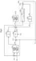
- FIG. 2 shows processes that are performed by the steering control device 40.
- the processes shown in FIG. 2 are implemented by the PU 42 repeatedly executing the steering control program 44a at, for example, predetermined cycles.
- a desired steering torque calculation process M10 is a process of calculating desired steering torque Th*, namely a desired value of the steering torque Th, based on an axial force Fa.
- the axial force Fa is a force that is applied to the steered shaft 16.
- the axial force Fa is an amount converted to torque of the transmission shaft 14.
- the desired steering torque calculation process M10 includes a process of setting the desired steering torque Th* to a different value according to the vehicle speed SPD even when the axial force Fa is the same. This is a setting intended to give the driver an optimal steering feel according to the vehicle speed SPD.
- the steering torque estimation process M32 is a process of outputting the estimated steering torque The by inputting the assist torque Ta to the nominal model Pn.
- the estimated steering torque The is steering torque estimated by the nominal model Pn.
- the assist torque Ta is a value obtained by subtracting the estimated second disturbance torque de from the sum of the open-loop manipulated variable Mff and the feedback manipulated variable Mfb.
- the estimated second disturbance torque de is an amount obtained by converting the difference between the steering torque estimated by the nominal model Pn and the actual steering torque Th to the torque of the assist motor 30. This means that the estimated second disturbance torque de is an amount according to the difference between the steering torque estimated by the nominal model Pn and the actual steering torque Th. Therefore, the assist torque Ta is an amount obtained by correcting the sum of the open-loop manipulated variable Mff and the feedback manipulated variable Mfb with a correction amount according to the difference between the steering torque estimated by the nominal model Pn and the actual steering torque Th.
- the PU 42 calculates the estimated second disturbance torque de using, as an input, the estimated first disturbance torque dhe that is the difference between the steering torque Th and the estimated steering torque The.
- the estimated second disturbance torque de indicates a disturbance element of the torque of the second portion of the transmission shaft 14. In other words, it indicates a disturbance element of the torque that is converted to a force for displacing the steered shaft 16.
- the nominal model Pn is configured to include not only the inertia coefficient J but also the viscosity coefficient C, the elastic modulus K, and the torsional stiffness coefficient Ktb. This allows the nominal model Pn to be an accurate approximate model of the actual controlled object.
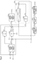
- FIG. 3 shows processes that are performed by the steering control device 40 according to the present embodiment. Of the processes shown in FIG. 3 , the processes corresponding to those shown in FIG. 2 are denoted by the same signs for convenience.
- the nominal model Pn is expressed by the following equation (c5). ⁇ Ktb / J ⁇ s ⁇ s
- the nominal model Pn does not have terms with the viscosity coefficient C and the elastic modulus K.
- the viscosity coefficient C and the elastic modulus K need to be estimated and determined from an actual vehicle.
- the inertia coefficient J is substantially determined by the inertia of the assist motor 30 and a damping ratio that is a ratio of the rotational speed of the transmission shaft 14 to the rotational speed of the assist motor 30 in the steering system 10.
- the torsional stiffness coefficient Ktb is determined by characteristics of the torsion bar 52 of the torque sensor 50. The workload required to design the nominal model Pn can thus be reduced by omitting the terms with the viscosity coefficient C and the elastic modulus K from the nominal model Pn.
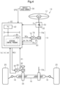
- FIG. 4 shows the configuration of a steering control system according to the present embodiment.
- the members corresponding to those shown in FIG. 1 are denoted by the same signs for convenience.
- the transmission shaft 14 is divided into an input shaft 14a connected to the steering wheel 12 and an output shaft 14b engaged with the steered shaft 16.
- the output shaft 14b is actually not required.
- the output shaft 14b is provided for convenience of the following description.
- Torque of a steering motor 80 is applied to the steered shaft 16 via the drive shaft 34.
- the steering motor 80 is, for example, a three-phase brushless motor.
- An output voltage of an inverter 82 is applied to a terminal of the steering motor 80.
- the steering system 10 is a controlled object of the steering control device 40.
- the steering control device 40 operates the inverter 72 in order to control the reaction force that is a controlled variable of the controlled object.
- the steering control device 40 operates the inverter 82 in order to control the steered angle of the steered wheels 20 that is a controlled variable of the controlled object.
- the steering control device 40 refers to a rotation angle ⁇ s of the reaction motor 70 detected by a rotation angle sensor 90, in order to control the reaction force that is a controlled variable.
- the steering control device 40 refers to currents ius, ivs, and iws flowing through the reaction motor 70, in order to control the reaction force.
- the steering control device 40 refers to a rotation angle ⁇ t of the steering motor 80 detected by a rotation angle sensor 92, in order to control the steered angle that is a controlled variable.
- the steering control device 40 refers to currents iut, ivt, and iwt flowing through the steering motor 80, in order to control the steered angle.
- FIG. 5 shows processes that are performed by the steering control device 40.
- FIG. 5 shows processes that are performed by the steering control device 40 in a state in which transmission of the power of the steering wheel 12 to the steered wheels 20 is disconnected.
- the processes corresponding to those shown in FIG. 2 are denoted by the same signs for convenience.
- the deviation calculation process M14 is a process of calculating a value obtained by subtracting the steering torque Th from the desired steering torque Th*.
- the torque command value calculation process M20 is a process of outputting a reaction force command value Tr*.
- the torque command value calculation process M20 is a process of substituting a value obtained by subtracting the estimated second disturbance torque de from the sum of the open-loop manipulated variable Mff and the feedback manipulated variable Mfb for the reaction force command value Tr*.
- the reaction force command value Tr* is a command value for the reaction torque to be applied to the steering wheel 12.
- the reaction force command value Tr* is a value converted to the angle of the transmission shaft 14.
- a steering operation signal generation process M40a is a process of operating the inverter 72 by inputting the reaction force command value Tr*.
- the steering operation signal generation process M40a includes a process of calculating a manipulated variable of control that uses the torque of the reaction motor 70 as a controlled variable and uses a value obtained by converting the reaction force command value Tr* to the torque of the reaction motor 70 as a desired value of the controlled variable.
- the rotation angle ⁇ s and the currents ius, ivs, and iws are referred to when calculating the manipulated variable.
- the steering operation signal generation process M40a includes a process of operating the inverter 72 according to the manipulated variable.
- An operation signal MSs for the inverter 72 is shown in FIG. 5 . However, the operation signal MSs is actually an individual operation signal for each switching element of the inverter 72.
- a desired angle calculation process M50 is a process of calculating a desired angle ⁇ p* that is a desired value of a rotation angle of the drive shaft 34.
- the rotation angle of the drive shaft 34 has a one-to-one correspondence with the steered angle.
- the desired angle calculation process M50 may be a process of calculating the desired angle ⁇ p* from the reaction force command value Tr* using, for example, a model of the steering system 10.
- the reaction force command value Tr* may be regarded as torque that is applied to the transmission shaft 14 on the assumption that the input shaft 14a and the output shaft 14b are mechanically connected.
- An angle control process M52 is a process of calculating a manipulated variable for controlling the rotation angle of the drive shaft 34 to the desired angle ⁇ p*.
- This manipulated variable is a steered torque command value Tt* that is a torque command value for the steering motor 80.
- a steered operation signal generation process M54 is a process of operating the inverter 82 by inputting the steered torque command value Tt*.
- the steered operation signal generation process M54 includes a process of calculating a manipulated variable of control that uses the torque of the steering motor 80 as a controlled variable and uses an amount obtained by converting the steered torque command value Tt* to the torque of the steering motor 80 as a desired value of the controlled variable.
- the rotation angle ⁇ t and the currents iut, ivt, and iwt are referred to when calculating the manipulated variable.
- the steered operation signal generation process M54 includes a process of operating the inverter 82 according to the manipulated variable.
- An operation signal MSt for the inverter 82 is shown in FIG. 5 . However, the operation signal MSt is actually an individual operation signal for each switching element of the inverter 82.
- the polynomial in the denominator of the transfer function of the nominal model Pn may include a zeroth-order term.
- the denominator of the transfer function of the nominal model Pn may include a zeroth-order term of the differential operator.
Landscapes
- Engineering & Computer Science (AREA)
- Chemical & Material Sciences (AREA)
- Mechanical Engineering (AREA)
- Transportation (AREA)
- Combustion & Propulsion (AREA)
- Power Engineering (AREA)
- Computer Vision & Pattern Recognition (AREA)
- Software Systems (AREA)
- Physics & Mathematics (AREA)
- General Physics & Mathematics (AREA)
- Automation & Control Theory (AREA)
- Medical Informatics (AREA)
- Evolutionary Computation (AREA)
- Artificial Intelligence (AREA)
- Health & Medical Sciences (AREA)
- Steering Control In Accordance With Driving Conditions (AREA)
- Power Steering Mechanism (AREA)
Applications Claiming Priority (1)
| Application Number | Priority Date | Filing Date | Title |
|---|---|---|---|
| PCT/JP2022/032753 WO2024047787A1 (ja) | 2022-08-31 | 2022-08-31 | 操舵制御装置、および操舵制御方法 |
Publications (2)
| Publication Number | Publication Date |
|---|---|
| EP4582331A1 true EP4582331A1 (de) | 2025-07-09 |
| EP4582331A4 EP4582331A4 (de) | 2025-10-15 |
Family
ID=90098951
Family Applications (1)
| Application Number | Title | Priority Date | Filing Date |
|---|---|---|---|
| EP22957386.0A Pending EP4582331A4 (de) | 2022-08-31 | 2022-08-31 | Lenksteuerungsvorrichtung und lenksteuerungsverfahren |
Country Status (5)
| Country | Link |
|---|---|
| US (1) | US20260048786A1 (de) |
| EP (1) | EP4582331A4 (de) |
| JP (1) | JP7772237B2 (de) |
| CN (1) | CN119731070A (de) |
| WO (1) | WO2024047787A1 (de) |
Families Citing this family (1)
| Publication number | Priority date | Publication date | Assignee | Title |
|---|---|---|---|---|
| WO2025158649A1 (ja) * | 2024-01-26 | 2025-07-31 | 株式会社ジェイテクト | 操舵制御装置 |
Family Cites Families (8)
| Publication number | Priority date | Publication date | Assignee | Title |
|---|---|---|---|---|
| JP3132299B2 (ja) * | 1994-09-01 | 2001-02-05 | 日産自動車株式会社 | 車両用補助舵角制御装置 |
| JP4161707B2 (ja) | 2002-12-24 | 2008-10-08 | 株式会社ジェイテクト | 電動パワーステアリング装置 |
| JP4915305B2 (ja) | 2007-07-16 | 2012-04-11 | 株式会社デンソー | 電動パワーステアリング装置の制御装置 |
| DE102010030986B4 (de) | 2010-07-06 | 2022-02-24 | Robert Bosch Gmbh | Verfahren zur Bestimmung einer Zahnstangenkraft für eine Lenkvorrichtung in einem Fahrzeug |
| WO2018089898A2 (en) | 2016-11-10 | 2018-05-17 | Ohio University | Autonomous automobile guidance and trajectory-tracking |
| JP2019151180A (ja) | 2018-03-01 | 2019-09-12 | 国立大学法人群馬大学 | Eps用制御装置 |
| JP7388254B2 (ja) | 2020-03-09 | 2023-11-29 | 株式会社ジェイテクト | 操舵制御装置 |
| JP7334656B2 (ja) | 2020-03-09 | 2023-08-29 | 株式会社ジェイテクト | モータの制御装置 |
-
2022
- 2022-08-31 WO PCT/JP2022/032753 patent/WO2024047787A1/ja not_active Ceased
- 2022-08-31 EP EP22957386.0A patent/EP4582331A4/de active Pending
- 2022-08-31 JP JP2024543685A patent/JP7772237B2/ja active Active
- 2022-08-31 CN CN202280099160.9A patent/CN119731070A/zh active Pending
- 2022-08-31 US US19/101,742 patent/US20260048786A1/en active Pending
Also Published As
| Publication number | Publication date |
|---|---|
| US20260048786A1 (en) | 2026-02-19 |
| JPWO2024047787A1 (de) | 2024-03-07 |
| CN119731070A (zh) | 2025-03-28 |
| JP7772237B2 (ja) | 2025-11-18 |
| EP4582331A4 (de) | 2025-10-15 |
| WO2024047787A1 (ja) | 2024-03-07 |
Similar Documents
| Publication | Publication Date | Title |
|---|---|---|
| EP3156308B1 (de) | Lenksteuerungsvorrichtung | |
| JP5126357B2 (ja) | 車両の操舵装置 | |
| JP2020029194A (ja) | 操舵制御装置 | |
| CN111845915B (zh) | 转动控制系统 | |
| US11794806B2 (en) | Control apparatus for steering system | |
| EP4582331A1 (de) | Lenksteuerungsvorrichtung und lenksteuerungsverfahren | |
| EP4620779A1 (de) | Motorsteuerungsvorrichtung | |
| EP4582332A1 (de) | Lenksteuerungsvorrichtung und lenksteuerungsverfahren | |
| EP4582333A1 (de) | Lenksteuerungsvorrichtung und lenksteuerungsverfahren | |
| EP4393793A1 (de) | Lenksteuervorrichtung | |
| EP4474248A1 (de) | Lenksteuerungsvorrichtung und lenksteuerungsverfahren | |
| JP2024130883A (ja) | 操舵制御装置および操舵制御方法 | |
| EP4729391A1 (de) | Lenksteuerungsvorrichtung und lenksteuerungsverfahren | |
| CN119058805B (zh) | 转向操纵控制装置 | |
| JP7772104B2 (ja) | 操舵制御装置、および操舵制御方法 | |
| EP4530161A1 (de) | Lenksteuerungsvorrichtung und lenksteuerungsverfahren | |
| JP7786478B2 (ja) | 操舵制御装置 | |
| US20240400134A1 (en) | Steering control device | |
| WO2025134237A1 (ja) | 操舵制御装置、および操舵制御方法 | |
| EP4737272A1 (de) | Lenksteuerungsvorrichtung und lenksteuerungsverfahren | |
| JP2025124249A (ja) | 転舵制御装置 |
Legal Events
| Date | Code | Title | Description |
|---|---|---|---|
| STAA | Information on the status of an ep patent application or granted ep patent |
Free format text: STATUS: THE INTERNATIONAL PUBLICATION HAS BEEN MADE |
|
| PUAI | Public reference made under article 153(3) epc to a published international application that has entered the european phase |
Free format text: ORIGINAL CODE: 0009012 |
|
| STAA | Information on the status of an ep patent application or granted ep patent |
Free format text: STATUS: REQUEST FOR EXAMINATION WAS MADE |
|
| 17P | Request for examination filed |
Effective date: 20250311 |
|
| AK | Designated contracting states |
Kind code of ref document: A1 Designated state(s): AL AT BE BG CH CY CZ DE DK EE ES FI FR GB GR HR HU IE IS IT LI LT LU LV MC MK MT NL NO PL PT RO RS SE SI SK SM TR |
|
| A4 | Supplementary search report drawn up and despatched |
Effective date: 20250917 |
|
| RIC1 | Information provided on ipc code assigned before grant |
Ipc: B62D 6/00 20060101AFI20250911BHEP Ipc: B62D 5/04 20060101ALI20250911BHEP Ipc: G05B 11/32 20060101ALI20250911BHEP Ipc: G05B 11/36 20060101ALI20250911BHEP Ipc: H02P 27/08 20060101ALI20250911BHEP |
|
| DAV | Request for validation of the european patent (deleted) | ||
| DAX | Request for extension of the european patent (deleted) |