EP4582345A1 - Flugkörper und verfahren zur steuerung des flugkörpers - Google Patents
Flugkörper und verfahren zur steuerung des flugkörpers Download PDFInfo
- Publication number
- EP4582345A1 EP4582345A1 EP23859965.8A EP23859965A EP4582345A1 EP 4582345 A1 EP4582345 A1 EP 4582345A1 EP 23859965 A EP23859965 A EP 23859965A EP 4582345 A1 EP4582345 A1 EP 4582345A1
- Authority
- EP
- European Patent Office
- Prior art keywords
- flight state
- function
- value
- deviation
- state
- Prior art date
- Legal status (The legal status is an assumption and is not a legal conclusion. Google has not performed a legal analysis and makes no representation as to the accuracy of the status listed.)
- Pending
Links
Images






Classifications
-
- G—PHYSICS
- G05—CONTROLLING; REGULATING
- G05D—SYSTEMS FOR CONTROLLING OR REGULATING NON-ELECTRIC VARIABLES
- G05D1/00—Control of position, course, altitude or attitude of land, water, air or space vehicles, e.g. using automatic pilots
- G05D1/60—Intended control result
- G05D1/654—Landing
- G05D1/6546—Emergency landing
-
- B—PERFORMING OPERATIONS; TRANSPORTING
- B64—AIRCRAFT; AVIATION; COSMONAUTICS
- B64D—EQUIPMENT FOR FITTING IN OR TO AIRCRAFT; FLIGHT SUITS; PARACHUTES; ARRANGEMENT OR MOUNTING OF POWER PLANTS OR PROPULSION TRANSMISSIONS IN AIRCRAFT
- B64D17/00—Parachutes
- B64D17/62—Deployment
-
- B—PERFORMING OPERATIONS; TRANSPORTING
- B64—AIRCRAFT; AVIATION; COSMONAUTICS
- B64U—UNMANNED AERIAL VEHICLES [UAV]; EQUIPMENT THEREFOR
- B64U70/00—Launching, take-off or landing arrangements
- B64U70/80—Vertical take-off or landing, e.g. using rockets
- B64U70/83—Vertical take-off or landing, e.g. using rockets using parachutes, balloons or the like
-
- G—PHYSICS
- G05—CONTROLLING; REGULATING
- G05D—SYSTEMS FOR CONTROLLING OR REGULATING NON-ELECTRIC VARIABLES
- G05D1/00—Control of position, course, altitude or attitude of land, water, air or space vehicles, e.g. using automatic pilots
- G05D1/20—Control system inputs
- G05D1/22—Command input arrangements
- G05D1/221—Remote-control arrangements
- G05D1/222—Remote-control arrangements operated by humans
- G05D1/223—Command input arrangements on the remote controller, e.g. joysticks or touch screens
-
- B—PERFORMING OPERATIONS; TRANSPORTING
- B64—AIRCRAFT; AVIATION; COSMONAUTICS
- B64D—EQUIPMENT FOR FITTING IN OR TO AIRCRAFT; FLIGHT SUITS; PARACHUTES; ARRANGEMENT OR MOUNTING OF POWER PLANTS OR PROPULSION TRANSMISSIONS IN AIRCRAFT
- B64D17/00—Parachutes
- B64D17/80—Parachutes in association with aircraft, e.g. for braking thereof
-
- B—PERFORMING OPERATIONS; TRANSPORTING
- B64—AIRCRAFT; AVIATION; COSMONAUTICS
- B64D—EQUIPMENT FOR FITTING IN OR TO AIRCRAFT; FLIGHT SUITS; PARACHUTES; ARRANGEMENT OR MOUNTING OF POWER PLANTS OR PROPULSION TRANSMISSIONS IN AIRCRAFT
- B64D45/00—Aircraft indicators or protectors not otherwise provided for
-
- B—PERFORMING OPERATIONS; TRANSPORTING
- B64—AIRCRAFT; AVIATION; COSMONAUTICS
- B64U—UNMANNED AERIAL VEHICLES [UAV]; EQUIPMENT THEREFOR
- B64U10/00—Type of UAV
- B64U10/10—Rotorcrafts
- B64U10/13—Flying platforms
- B64U10/14—Flying platforms with four distinct rotor axes, e.g. quadcopters
-
- G—PHYSICS
- G05—CONTROLLING; REGULATING
- G05D—SYSTEMS FOR CONTROLLING OR REGULATING NON-ELECTRIC VARIABLES
- G05D2109/00—Types of controlled vehicles
- G05D2109/20—Aircraft, e.g. drones
- G05D2109/25—Rotorcrafts
- G05D2109/254—Flying platforms, e.g. multicopters
Definitions
- the present disclosure relates to an aerial vehicle and a method of controlling an aerial vehicle.
- US Patent Publication No. 2017/0106986A1 discloses an unmanned aircraft that executes such a descent scenario.
- the unmanned aircraft in PTL 1 ejects a parachute on condition that an altitude is higher than a threshold value (20 feet), for example, when an inclination of the unmanned aircraft is larger than a threshold value (25 degrees) and a duration of such an inclined state is longer than a threshold value (2 seconds).
- the descent scenario is not started.
- the threshold value for example, a flight in which the inclination is 24 degrees
- a time period for example, 5 seconds
- the descent scenario is not started. Therefore, in PTL 1, the unmanned aircraft may crash during that time period. PTL 1 is thus not necessarily concluded as executing at appropriate timing, the descent scenario including ejection of the parachute.
- the present disclosure was made in view of the problems above, and provides an aerial vehicle and a method of controlling an aerial vehicle that enable ejection of a parachute at appropriate timing.
- a method of controlling an aerial vehicle that can eject a parachute includes detecting a flight state of the aerial vehicle and determining whether the parachute should be ejected based on a degree of deviation of the flight state from a reference range determined for the flight state and a duration for which a state of deviation equal to or more than the degree of deviation lasts.
- the parachute can be ejected at appropriate timing.
- An unmanned aircraft will be described below by way of example of an aerial vehicle. Specifically, a drone as the unmanned aircraft will be described by way of example. More specifically, a drone with rotary wings will be described by way of example. The present disclosure is also applicable to various manned aircrafts (other examples of the aerial vehicle) such as a "flying car.”
- a drone according to the present embodiment is adapted to automatic control and manual control by an operator (remote control with the use of a remote controller).
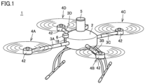
- Fig. 1 is a diagram showing a state that a drone is flying.
- Fig. 2 is a diagram showing a state of descent of the drone with a parachute having been ejected.
- a drone 1 includes a main body 2, four arms 3A, 3B, 3C, and 3D, four propulsive mechanisms 4A, 4B, 4C, and 4D, an ejection apparatus 5, a communication unit 6, and a support member 18.
- Each of propulsive mechanisms 4A, 4B, 4C, and 4D includes a propeller 41 (see Fig. 2 ) and a motor 42.
- any one arm of arms 3A, 3B, 3C, and 3D will also be referred to as an "arm 3" below.
- any one propulsive mechanism of propulsive mechanisms 4A, 4B, 4C, and 4D will also be referred to as a "propulsive mechanism 4.”
- Arm 3 is attached to main body 2.
- Arm 3 has a base end and a tip end.
- Arm 3 has the base end attached to main body 2.
- arm 3 extends from a side surface of main body 2.
- Propulsive mechanism 4 is attached to the tip end of arm 3.
- Motor 42 is attached to the tip end of arm 3.
- Propeller 41 is attached to a rotation shaft (not shown) of motor 42.
- a parachute 51 is accommodated in ejection apparatus 5.
- Ejection apparatus 5 ejects parachute 51 as shown in Fig. 2 when a flight state of drone 1 satisfies a predetermined condition.
- Ejection apparatus 5 senses drop or the like of drone 1 and instantaneously expands parachute 51 by activating a gas generator contained in ejection apparatus 5.
- An explosive gas generator pyrotechnic
- a non-explosive gas generator such as a canister type gas generator may be employed as the gas generator.
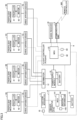
- drone 1 includes, in addition to propulsive mechanisms 4A, 4B, 4C, and 4D, ejection apparatus 5, and communication unit 6 described above, drive apparatuses (electronic speed controllers (ESCs)) 7A, 7B, 7C, and 7D, a flight controller (an autopilot) 8, a battery 9, a power supply module 10, a distributor 12, a battery 13, a trigger apparatus (auto trigger system (ATS)) 14, a sensor 15, and a global navigation satellite system (GNSS) receiver 16.
- ESCs electronic speed controllers
- propulsive mechanism 4 includes propeller 41 and motor 42.
- Drive apparatus 7 includes a micro controller unit (MCU) and a current driver which are not shown.
- MCU micro controller unit
- MCUs 81 and 141 each specifically include a central processing unit (CPU), a memory such as a read only memory (ROM) and a random access memory (RAM), and an input/output (I/O) circuit which are not shown.
- CPU central processing unit
- ROM read only memory
- RAM random access memory
- I/O input/output circuit
- Communication unit 6 is an apparatus for communication with a terrestrial apparatus.
- Communication unit 6 includes a wireless module and a long term evolution (LTE) module which are not shown.
- LTE long term evolution
- Distributor 12 distributes supplied electric power to each of four drive apparatuses 7.
- Distributor 12 allows electric power supplied through a power path R2 to be supplied to each of four drive apparatuses 7.
- distributor 12 allows electric power to be supplied to the current driver (not shown) of each of four drive apparatuses 7.
- the MUC (not shown) of drive apparatus 7 receives a command from MUC 81 of flight controller 8.
- the MCU of drive apparatus 7 controls a current fed by the current driver of drive apparatus 7 to the coil (not shown) of motor 42 based on the command.
- a rotation speed of motor 42 is controlled.
- a speed of rotation of propeller 41 can thus be controlled.
- GNSS receiver 16 and communication unit 6 are communicatively connected to MCU 81 of flight controller 8.
- GNSS receiver 16 and communication unit 6 receive supply of electric power from flight controller 8.
- GNSS receiver 16 and communication unit 6 operate with electric power from battery 9.
- GNSS receiver 16 receives radio waves emitted from a plurality of positioning satellites (not shown) and obtains the current position of drone 1 based on received radio waves. GNSS receiver 16 periodically sends information indicating the current position to flight controller 8. Specifically, GNSS receiver 16 periodically sends information on a latitude and a longitude of drone 1 as position information to MCU 81.
- Inertial apparatus 82 periodically measures the angular velocity and the acceleration of drone 1 in a three-dimensional space.
- IMU inertial measurement unit
- INU inertial navigation unit
- IRU inertial reference unit
- IGU inertial guidance unit
- AHRS attitude heading reference system
- Pressure altimeter 83 periodically measures the altitude from the ground level and the sea level similarly to pressure altimeter 143.
- Flight controller 8 controls flight of drone 1. Flight controller 8 realizes automatic control and manual control by a remote controller operation by the operator.
- flight controller 8 controls flight of drone 1 based on a predetermined flight route.
- MCU 81 of flight controller 8 implements autonomous flight of drone 1 based on the current position obtained by GNSS receiver 16 or the like, a result of detection by inertial apparatus 82, and a result of detection (altitude) by pressure altimeter 83.
- Flight controller 8 can transmit information on the current position of drone 1 through the LTE module described above.
- Flight controller 8 transmits the information on the current position of drone 1 to the terrestrial control station through the LTE module, based on occurrence of predetermined abnormality in drone 1.
- trigger apparatus 14 when the flight state satisfies the predetermined condition, trigger apparatus 14 sends a prescribed signal to flight controller 8.
- flight controller 8 When flight controller 8 receives the prescribed signal, it stops rotation of propeller 41. In other words, flight controller 8 forcibly stops the flight.
- trigger apparatus 14 sends a command to eject parachute 51 to ejection apparatus 5.
- eject parachute 51 to ejection apparatus 5.
- Sensor 15 detects whether or not ejection apparatus 5 has been activated. Sensor 15 is communicatively connected to flight controller 8. Flight controller 8 transmits through the LTE module to the terrestrial control station, the fact of forced stop of the flight and the result of detection by sensor 15.
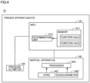
- Fig. 4 is a diagram showing an exemplary configuration of trigger apparatus 14.
- inertial apparatus 142 includes a gyro 1421, an accelerometer 1422, and a processor 1423.
- inertial apparatus 142 includes three gyros and three accelerometers for axes (an X axis, a Y axis, and a Z axis) of a three-dimensional rectangular coordinate system.
- Processor 1423 may be provided in MCU 141. Processor 1423 should only be in trigger apparatus 14.
- any of an inertial measurement unit (IMU), an inertial navigation unit (INU), an inertial reference unit (IRU), an inertial guidance unit (IGU), and an attitude heading reference system (AHRS) can be employed as inertial apparatus 142 similarly to inertial apparatus 82.
- IMU inertial measurement unit
- INU inertial navigation unit
- IRU inertial reference unit
- IGU inertial guidance unit
- AHRS attitude heading reference system
- a forward travel direction of drone 1 is defined as a positive direction along the X axis and a rearward travel direction of drone 1 is defined as a negative direction along the X axis.
- a left movement direction of drone 1 is defined as the positive direction along the Y axis and a right movement direction of drone 1 is defined as the negative direction along the Y axis.
- Gyro 1421 detects a rotational motion of drone 1.
- Accelerometer 1422 detects a translation motion of drone 1 along each axial direction. Specifically, in the present example, gyro 1421 outputs angular velocities around the three axes to processor 1423. Accelerometer 1422 outputs the accelerations in directions along the three axes to processor 1423.
- Processor 1423 calculates at least angular velocities around the three axes, accelerations in the directions along the three axes, attitude angles (a roll angle, a pitch angle, and a yaw angle (direction angles)), a velocity, and a position.
- the angular velocity around the X axis among the angular velocities around the three axes is also referred to as a "roll angular velocity" below.
- the angular velocity around the Y axis among the angular velocities around the three axes is also referred to as a "pitch angular velocity.”
- the angular velocity around the Z axis among the angular velocities around the three axes is also referred to as a “yaw angular velocity.”
- MCU 141 includes a memory 1411 and a determination unit 1412.
- a function Va(x) and a function Vb(t) are stored in memory 1411. Details of function Va(x) and function Vb(t) will be described later.
- Determination unit 1412 of MCU 141 determines whether or not an operation to eject parachute 51 is required based on function Va(x) and function Vb(t) stored in memory 1411. Details of such determination processing will also be described later.
- Fig. 5 is a front view of remote controller 900 for an operator to control drone 1.
- remote controller 900 includes control levers 910 and 920.
- a method of controlling drone 1 includes two types of a "mode 1" and a "mode 2.” A case of "mode 1" will be described below.
- drone 1 ascends.
- drone 1 moves to the right when viewed from the operator.
- drone 1 descends.
- drone 1 moves to the left when viewed from the operator.
- drone 1 travels forward.
- drone 1 turns to the right.
- drone 1 travels rearward.
- drone 1 turns to the left.
- a technique to set a flight envelope will now be described. Specifically, a technique to set a reference range (a range indicated by a threshold value) determined for a flight state will be described. Setting of a threshold value of a resultant acceleration in the directions along the three axes, setting of a threshold value of the angular velocity, and setting of a threshold value of the attitude angle will be described by way of example.
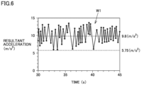
- Fig. 6 is a diagram for illustrating setting of the threshold value of the resultant acceleration.
- the operator operates control lever 910 of remote controller 900 to repeatedly move drone 1 in a vertical direction (an upward-downward direction). Specifically, the operator alternately repeats an operation to tilt control lever 910 in the direction shown with arrow 951 and an operation to tilt control lever 910 in the direction shown with arrow 953.
- the operator operates control lever 910 by an amount of operation at a prescribed ratio (for example, approximately 70 percent) to a maximum amount of operation in the directions shown with arrows 951 and 953.
- inertial apparatus 142 obtains a waveform W1 of the resultant acceleration as shown in Fig. 6 .
- Waveform W1 is shown, with the abscissa representing time and the ordinate representing the resultant acceleration.
- Waveform W1 sways up and down around points where the resultant acceleration attains to 9.8 m/s 2 .
- a state at the resultant acceleration of 9.8 m/s 2 represents a state in which the acceleration in a vertically upward direction and the acceleration (gravity) in a vertically downward direction are balanced.
- the state at the resultant acceleration of 9.8 m/s 2 represents a state in which force to have drone 1 ascend and force to have drone 1 descend are balanced.
- a value "5.75 m/s 2 " on the ordinate of waveform W1 represents a lower limit value (minimum value) of the resultant acceleration.
- "5.75 m/s 2 " represents the lower limit value of the resultant acceleration measured by inertial apparatus 142 in normal operations.
- drone 1 descends at 4.05 m/s 2 which is a difference from 9.8 m/s 2 .
- the lower limit value of waveform W1 is defined as a lower limit value of the flight envelope of the resultant acceleration.
- the lower limit value serves as the threshold value for classification into a flight state that satisfies the flight envelope and a flight state that does not satisfy the flight envelope.
- the resultant acceleration lower than 5.75 m/s 2 indicates deviation from the flight envelope in connection with the resultant acceleration.
- Fig. 7 is a diagram for illustrating setting of the threshold value of the angular velocity (the roll angular velocity in the present example).
- Fig. 8 is a diagram for illustrating setting of the threshold value of the attitude angle (the roll angle in the present example).
- the operator operates control lever 910 of remote controller 900 to repeatedly move drone 1 in a left-right direction. Specifically, the operator alternately repeats the operation to tilt control lever 910 in the direction shown with arrow 952 and the operation to tilt control lever 910 in the direction shown with arrow 954.
- the operator operates control lever 910 by an amount of operation at a prescribed ratio (for example, approximately 70 percent) to a maximum amount of operation in the directions shown with arrows 952 and 954.
- inertial apparatus 142 obtains a waveform W2 in connection with the angular velocity as shown in Fig. 7 and a waveform W3 in connection with the attitude angle as shown in Fig. 8 .
- a value "60 deg/s" on the ordinate of waveform W2 represents an upper limit value (maximum value) of the angular velocity.
- the value represents the upper limit value of the angular velocity measured by inertial apparatus 142 in normal operations.
- the upper limit value of waveform W2 is defined as an upper limit value of the flight envelope of the angular velocity (the angular velocity around the X axis in the present example).
- the upper limit value serves as the threshold value for classification into the flight state that satisfies the flight envelope and the flight state that does not satisfy the flight envelope.
- the angular velocity higher than 60 deg/s indicates deviation from the flight envelope in connection with the angular velocity.
- a value "-60 deg/s" on the ordinate of waveform W2 represents a lower limit value (minimum value) of the angular velocity.
- the value represents the lower limit value of the angular velocity measured by inertial apparatus 142 in normal operations.
- the lower limit value of waveform W2 is defined as a lower limit value of the flight envelope of the angular velocity (the roll angular velocity in the present example).
- the lower limit value serves as the threshold value for classification into the flight state that satisfies the flight envelope and the flight state that does not satisfy the flight envelope.
- the angular velocity lower than -60 deg/s indicates deviation from the flight envelope in connection with the angular velocity.
- the range of the flight envelope of the roll angular velocity is thus set to a range not smaller than -60 deg/s and not larger than 60 deg/s.
- the range of the flight envelope of the pitch angular velocity is also set with a similar technique. Without being limited as such, in consideration of a geometry of drone 1, the range of the flight envelope of the pitch angular velocity may be the same as the range of the flight envelope of the roll angular velocity.
- a value "20.4 deg” on the ordinate of waveform W3 represents an upper limit value (maximum value) of the attitude angle.
- “20.4 deg” represents the upper limit value of the attitude angle measured by inertial apparatus 142 in normal operations.
- the upper limit value of waveform W3 is defined as an upper limit value of the flight envelope of the angular velocity (the roll angle in the present example).
- the upper limit value serves as the threshold value for classification into the flight state that satisfies the flight envelope and the flight state that does not satisfy the flight envelope.
- the attitude angle larger than 20.4 deg indicates deviation from the flight envelope in connection with the attitude angle.
- a value "-15.0 deg” on the ordinate of waveform W3 represents a lower limit value (minimum value) of the attitude angle.
- "-15.0 deg” represents the lower limit value of the attitude angle (the roll angle in the present example) measured by inertial apparatus 142 in normal operations.
- the lower limit value of the attitude angle is set to a value (that is, "-20.4 deg") calculated by multiplying the upper limit value of the attitude angle by "-1".
- the lower limit value serves as the threshold value for classification into the flight state that satisfies the flight envelope and the flight state that does not satisfy the flight envelope.
- the attitude angle smaller than -20.4 deg indicates deviation from the flight envelope in connection with the attitude angle.
- the range of the flight envelope of the attitude angle (the roll angle in the present example) is thus set to a range not smaller than -20.4 deg and not larger than 20.4 deg.
- the range of the flight envelope of the pitch angle is also set with a similar technique. Without being limited as such, in consideration of the geometry of drone 1, the range of the flight envelope of the pitch angle may be the same as the range of the flight envelope of the roll angle.
- the range of the flight envelope in connection with variation in altitude per time of drone 1 is set based on control of drone 1 as above and analysis of the waveforms obtained under such control.
- MCU 141 sets the range of the flight envelope in connection with variation in altitude, based on a result of detection (altitude) by pressure altimeter 143.
- MCU 141 may be configured to set the range of the flight envelope in connection with variation in altitude based on a result of detection by accelerometer 1422.
- Function Va(x) and function Vb(t) stored in memory 1411 are functions relating to the resultant acceleration in the present example. Function Va(x) and function Vb(t) will be described below and thereafter control with the use of function Va(x) and function Vb(t) will be described.
- the value "5.75 m/s 2 " is the lower limit value of the resultant acceleration described with reference to Fig. 6 .
- the value of the function at the time when the resultant acceleration is 5.75 m/s 2 is 0.1.
- the value of the function at the time when the resultant acceleration is 3.75 m/s 2 is 0.9.
- Va(x) is expressed in an expression (2) and an expression (3) below.
- Va x ⁇ 0.4 x + 2.4 3.75 ⁇ x ⁇ 5.75
- Va x 0 x ⁇ 3.75 , 5.75 ⁇ x
- the value of y increases to the degree of deviation (a difference between x and 5.75) of the flight state from the flight envelope.
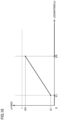
- Fig. 10 is a diagram showing function Vb(t).
- function Vb(t) is a function in which a duration of deviation from the flight envelope is expressed as an independent variable (x) and a value of the dependent variable (y) thereof is in proportion to the duration.
- the range of the value of the dependent variable of function Vb(t) is not smaller than 0 and smaller than 1. In other words, the value of the dependent variable of function Vb(t) is not equal to or larger than 1.
- function Vb(t) is a membership function. In the range of x not smaller than 0.1 s and not larger than 0.5 s, the value of y is in proportion to the degree of deviation of the flight state from the flight envelope. In function Vb(t), the value of the function at the time when the duration is 0.1 s is 0.1. The value of the function at the time when the duration is 0.5 s is 0.9.
- Vb(t) is expressed in an expression (4) and an expression (5) below.
- Vb t 2 t ⁇ 0.1 0.1 ⁇ t ⁇ 0.5
- Vb t 0 t ⁇ 0.1 , 0.5 ⁇ t
- the value of y increases in proportion to the value of the duration.
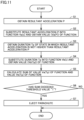
- Fig. 11 is a flowchart for illustrating a flow of processing performed in one aspect. Steps S1 to S7 in Fig. 11 are repeatedly performed every prescribed control cycle (for example, every 0.01 second).
- step S1 MCU 141 of trigger apparatus 14 obtains a resultant acceleration P from inertial apparatus 142.
- step S2 MCU 141 substitutes resultant acceleration P as the value of x into function Va(x) to obtain the value (Va(P)) of the function.
- MCU 141 when MCU 141 obtains a resultant acceleration P1 in step S1, it obtains the value (Va(P1)) of the function in step S2.
- Va(P1) is a value not smaller than 0.1 and smaller than 0.9.
- MCU 141 obtains a resultant acceleration P2 in step S1, it obtains the value (Va(P2)) of the function in step S2.
- Va(P1) is a value larger than 0.1 and not larger than 0.9.
- step S3 MCU 141 obtains a duration Tp of a state in which the resultant acceleration is not higher than resultant acceleration P.
- MCU 141 individually obtains a duration Tp1 of a state in which the resultant acceleration is not higher than resultant acceleration P1 and a duration Tp2 of a state in which the resultant acceleration is not higher than resultant acceleration P2.
- MCU 141 thus performs a plurality of timer functions.
- MCU 141 When the sum of function Va(P) and function Vb(Tp) exceeds 1 which is the threshold value (YES in step S6), MCU 141 has ejection apparatus 5 eject parachute 51. When the sum of function Va(P) and function Vb(Tp) does not exceed 1 which is the threshold value (NO in step S6), MCU 141 makes transition to the next control cycle and performs step S1 again.
- Drone 1 is summarized as below.
- MCU 141 determines that the total value of the value of the dependent variable of function Va(x) and the value of the dependent variable of function Vb(t) during the flight of drone 1 has exceeded the predetermined threshold value (1 in the present example), MCU 141 has ejection apparatus 5 eject parachute 51.
- parachute 51 can be ejected based on the degree of deviation from the flight envelope and the duration for which the state of deviation equal to or more than the degree of deviation lasts, and parachute 51 can be ejected based on a result of determination.
- control as below is specifically enabled.
- MCU 141 determines based on the result of detection by inertial apparatus 142 that the flight state has made transition from the stable flight state within the flight envelope (reference range) to the first deviated flight state (for example, the state at resultant acceleration P1 shown in Fig. 9 )
- MCU 141 calculates the first total value of the value (Va(P1)) of the dependent variable of function Va(x) based on the first deviated flight state and the value (Vb(Tp1)) of the dependent variable of function Vb(t) based on duration Tp for which the state of deviation equal to or more than the degree of deviation in the first deviated flight state lasts.
- MCU 141 has ejection apparatus 5 eject parachute 51.
- MCU 141 determines based on the result of detection by inertial apparatus 142 that the flight state has further made transition from the first deviated flight state to the second deviated flight state (for example, the state at resultant acceleration P2 shown in Fig. 9 ) that more greatly deviates from the flight envelope than the first deviated flight state, MCU 141 performs processing below.
- MCU 141 calculates again the first total value described above. Furthermore, MCU 141 calculates the second total value of the value (Va(P2)) of the dependent variable of function Va(x) based on the second deviated flight state and the value (Vb(Tp2)) of the dependent variable of function Vb(t) based on the duration (Tp2) for which the state of deviation equal to or more than the degree of deviation of the second deviated flight state lasts.
- MCU 141 When at least one of the first total value and the second total value exceeds the threshold value (1 in the present example), MCU 141 has ejection apparatus 5 eject parachute 51.
- MCU 141 When the flight state successively increases in degree of deviation such as the first deviated flight state, the second deviated flight state, ..., and an nth deviated flight state (n being a natural number not smaller than 3), MCU 141 performs processing below.
- k is defined as any natural number not smaller than 3 and not larger than n below.
- MCU 141 determines that the flight state has further made transition from a k-1th deviated flight state to a kth deviated flight state that more greatly deviates from the flight envelope than the k-1th deviated flight state
- MCU 141 calculates a kth total value of the value of the dependent variable of function Va(x) based on the kth deviated flight state and the value of the dependent variable of function Vb(t) based on the duration for which the state of deviation equal to or more than the degree of deviation of the kth deviated flight state lasts.
- MCU 141 has ejection apparatus 5 eject parachute 51.
- Function Va(x) and function Vb(t) are membership functions.
- the threshold value is set to 1.
- the range of the value of the dependent variable of function Va(x) is not smaller than 0 and smaller than 1.
- the range of the value of the dependent variable of function Vb(t) is not smaller than 0 and smaller than 1. According to such a configuration, each of the value of function Va(x) alone and the value of function Va(x) alone does not exceed 1. Therefore, in drone 1, ejection of parachute 51 based only on the degree of deviation from the flight envelope and ejection of parachute 51 based only on the duration of deviation can be prevented.
- a function Va'(x) instead of function Va(x) is stored.
- a function Vb'(t) instead of function Vb(t) is stored.
- a data table DT ( Fig. 14 ) is stored in memory 1411. Function Va'(x) and function Vb'(t) are included in data table DT.
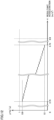
- Fig. 12 is a diagram showing function Va'(x).
- function Va'(x) is a function in which the flight state (specifically, the resultant acceleration) of drone 1 is expressed by the independent variable (that is, x) and the value of the dependent variable (that is, y) is in proportion to the degree of deviation of the flight state from the reference range (flight envelope) determined for the flight state.
- the range of the value of the dependent variable of function Va'(x) is not smaller than 0 and smaller than 1. In other words, the value of the dependent variable of function Va'(x) is not equal to or larger than 1.
- function Va'(x) is a step function.
- the value of y is stepwise in proportion to the degree of deviation of the flight state from the flight envelope.
- Function Va'(x) is stepwise in the range not smaller than 3.75 m/s 2 and not larger than 5.75 m/s 2 .
- function Va'(x) has the value of 0.1 at the time when the resultant acceleration is 5.75 m/s 2 and the value of 0.9 at the time when the resultant acceleration is 3.75 m/s 2 .
- the value "5.75 m/s 2 " is the lower limit value of the resultant acceleration described with reference to Fig. 6 .
- the value of y increases to the degree of deviation (difference between x and 5.75) of the flight state from the flight envelope.
- a specific example of the value of the function in the range not smaller than 3.75 m/s 2 and not larger than 5.75 m/s 2 is shown in data table DT.
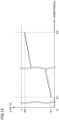
- Fig. 13 is a diagram showing function Vb'(t).
- function Vb'(t) is a function in which the duration of deviation from the flight envelope is expressed by the independent variable (x) and the value of the dependent variable (y) is in proportion to the duration.
- the range of the value of the dependent variable of function Vb'(t) is not smaller than 0 and smaller than 1. In other words, the value of the dependent variable of function Vb'(t) is not equal to or larger than 1.
- function Vb'(t) is a step function.
- the value of y is stepwise in proportion to the degree of deviation of the flight state from the flight envelope.
- Function Vb'(t) is stepwise in the range not smaller than 0.1 s and not larger than 0.5 s.
- function Vb'(t) has the value of 0.1 at the time when the duration is 0.1 s and has the value of 0.9 at the time when the duration is 0.5 s.
- a specific example of the value of the function in the range not smaller than 0.1 s and not larger than 0.5 s is shown in data table DT.
- Fig. 14 is a diagram showing data table DT. As shown in Fig. 14 , data table DT includes function Va'(x) and function Vb'(t).
- data table DT includes for function Va'(x), the threshold value of each resultant acceleration (x) in the range not smaller than 3.75 m/s 2 and not larger than 5.75 m/s 2 and the value (Va'(x)) of the function corresponding to each resultant acceleration (x).
- the resultant acceleration (x) is set in decrements of 0.05 m/s 2 .
- Data table DT includes for function Vb'(t), the threshold value of the duration (t) in the range not smaller than 0.1 s and not larger than 0.5 s and the value (Vb'(t)) of the function corresponding to each duration (t).
- the duration (t) is set in decrements of 0.01 s.
- MCU 141 determines whether or not parachute 51 should be ejected by referring to data table DT. Specifically, MCU 141 determines whether or not parachute 51 should be ejected by referring to the plurality of combinations of the threshold value of the resultant acceleration (x) and the threshold value of the duration (t) shown as patterns #1 to #41.
- Fig. 15 is a flowchart for illustrating a flow of processing performed in one aspect. Steps S11 to S14 in Fig. 15 are repeatedly performed every prescribed control cycle (for example, every 0.01 second).
- step S11 MCU 141 of trigger apparatus 14 obtains resultant acceleration P from inertial apparatus 142.
- step S12 MCU 141 compares resultant acceleration P with the threshold values of a plurality of resultant accelerations (x) by referring to data table DT, and obtains the threshold value of the duration (t) smaller than resultant acceleration P and closest to resultant acceleration P.
- step S1 when MCU 141 obtains in step S1, 5.75 m/s 2 (which is also referred to as a "resultant acceleration P3" below) as the resultant acceleration (x), in step S2, it obtains 0.5 s (which is also referred to as a “threshold value Tp3" below) as the threshold value of the duration (t) as shown with pattern #1.
- step S2 when MCU 141 obtains in step S1, 5.73 m/s 2 as the resultant acceleration (x), in step S2, it obtains 0.5 s (threshold value Tp3) as the threshold value of the duration (t) as shown with pattern #1.
- step S1 When MCU 141 obtains in step S1, 5.7 m/s 2 (which is also referred to as a "resultant acceleration P4" below) as the resultant acceleration (x), in step S2, it obtains 0.49 s (which is also referred to as a "threshold value Tp4" below) as the threshold value of the duration (t) as shown with pattern #2.
- step S1 5.68 m/s 2 as the resultant acceleration (x)
- step S2 it obtains 0.46 s (threshold value Tp4) as the threshold value of the duration (t) as shown with pattern #2.
- step S13 MCU 141 determines whether or not the duration of the state in which the resultant acceleration is not higher than resultant acceleration P has become equal to or larger than the threshold value of duration t brought in correspondence with resultant acceleration P. For example, when MCU 141 obtains resultant acceleration P3 in step S11, it determines whether or not the duration of the state in which the resultant acceleration is not higher than resultant acceleration P3 is equal to or larger than threshold value Tp3 of duration t brought in correspondence with resultant acceleration P3.
- MCU 141 When MCU 141 consecutively obtains resultant acceleration P3 in step S11 over at least one control cycle and thereafter consecutively obtains resultant acceleration P4 in step S11 over at least one control cycle, it performs processing below. Specifically, MCU 141 determines whether or not the duration of the state in which the resultant acceleration is not higher than resultant acceleration P3 has become equal to or larger than threshold value Tp3 of duration t brought in correspondence with resultant acceleration P3 and whether or not the duration of the state in which the resultant acceleration is not higher than resultant acceleration P4 has become equal to or larger than threshold value Tp4 of duration t brought in correspondence with resultant acceleration P4.
- step S14 MCU 141 has ejection apparatus 5 eject parachute 51 by sending a command to trigger apparatus 14.
- MCU 141 makes transition to the next control cycle and performs step S11 again.
- Drone 1 according to the present embodiment is summarized as below.
- MCU 141 determines that the total value of the value of the dependent variable of function Va'(x) during the flight of drone 1 and the value of the dependent variable of function Vb'(t) has exceeded the predetermined threshold value (1 in the present example), it has ejection apparatus 5 eject parachute 51.
- parachute 51 can be ejected based on the degree of deviation from the flight envelope and the duration for which the state of deviation equal to or more than the degree of deviation lasts, and parachute 51 can be ejected based on a result of determination.
- Function Va'(x) and function Vb'(t) are step functions.
- MCU 141 stores in advance a first duration (for example, the threshold value of 0.5 second) of deviation for which the total value of the value (for example, 0.1) of the dependent variable of function Va'(x) based on the first deviated flight state (for example, resultant acceleration of 5.75 m/s 2 ) that deviates from the flight envelope (reference range) among the plurality of flight states and the value of the dependent variable of function Vb'(t) has reached the threshold value (1 in the present example), in association with the first deviated flight state.
- a first duration for example, the threshold value of 0.5 second
- the total value of the value for example, 0.1
- the dependent variable of function Va'(x) based on the first deviated flight state for example, resultant acceleration of 5.75 m/s 2
- MCU 141 when the flight state has made transition from the stable flight state within the flight envelope to the first deviated flight state (for example, the resultant acceleration of 5.75 m/s 2 ) and then the duration for which the deviated state equal to or more than the degree of deviation of the first deviated flight state lasts exceeds the first duration (for example, 0.5 second), MCU 141 has ejection apparatus 5 eject parachute 51.
- MCU 141 stores a second duration (for example, the threshold value of 0.49 second) of deviation for which the total value of the value (for example, 0.12) of the dependent variable of function Va'(x) based on the second deviated flight state (for example, resultant acceleration of 5.7 m/s 2 ) that more greatly deviates from the flight envelope than the first deviated flight state among the plurality of flight states and the value of the dependent variable of function Vb'(t) has reached the threshold value (1 in the present example), in association with the second deviated flight state.
- a second duration for example, the threshold value of 0.49 second
- the second deviated flight state for example, resultant acceleration of 5.7 m/s 2
- MCU 141 has ejection apparatus 5 eject parachute 51.
- the first condition is that the duration for which the state of deviation equal to or more than the degree of deviation of the first deviated flight state lasts exceeds the first duration (the threshold value of 0.5 second).
- the second condition is that the duration for which the state of deviation equal to or more than the degree of deviation of the second deviated flight state lasts exceeds the second duration (the threshold value of 0.49 second).
- parachute 51 can be ejected based on the degree of deviation from the flight envelope and the duration for which the state of deviation equal to or more than the degree of deviation lasts, and parachute 51 can be ejected based on a result of determination.
- the threshold value of the duration (t) is brought in correspondence with each threshold value of the resultant acceleration (x). Therefore, the sum of the value of the dependent variable of function Va'(x) (the value of the function) and the value of the dependent variable of function Vb'(t) (the value of the function) does not have to be calculated each time. Therefore, an amount of computation processing in MCU 141 can be smaller than in the first embodiment.
- MCU 141 stores a kth duration of deviation for which the total value of the value of the dependent variable of function Va'(x) based on the kth deviated flight state that more greatly deviates from the flight envelope than the k-1 deviated flight state among the plurality of flight states and the value of the dependent variable of function Vb'(t) has reached the threshold value, in association with the kth deviated flight state.
- MCU 141 has ejection apparatus 5 eject parachute 51.
- the first condition is that the duration for which the state of deviation equal to or more than the degree of deviation of the first deviated flight state lasts exceeds the first duration.
- the second condition is that the duration for which the state of deviation equal to or more than the degree of deviation of the second deviated flight state lasts exceeds the second duration.
- the kth condition (the third condition to the nth condition) is that the duration for which the state of deviation equal to or more than the degree of deviation of the kth deviated flight state lasts exceeds the kth duration.
Landscapes
- Engineering & Computer Science (AREA)
- Aviation & Aerospace Engineering (AREA)
- Radar, Positioning & Navigation (AREA)
- Remote Sensing (AREA)
- Physics & Mathematics (AREA)
- General Physics & Mathematics (AREA)
- Automation & Control Theory (AREA)
- Control Of Position, Course, Altitude, Or Attitude Of Moving Bodies (AREA)
- Toys (AREA)
Applications Claiming Priority (2)
| Application Number | Priority Date | Filing Date | Title |
|---|---|---|---|
| JP2022136175A JP2024032495A (ja) | 2022-08-29 | 2022-08-29 | 飛行体および飛行体の制御方法 |
| PCT/JP2023/028429 WO2024048196A1 (ja) | 2022-08-29 | 2023-08-03 | 飛行体および飛行体の制御方法 |
Publications (1)
| Publication Number | Publication Date |
|---|---|
| EP4582345A1 true EP4582345A1 (de) | 2025-07-09 |
Family
ID=90099257
Family Applications (1)
| Application Number | Title | Priority Date | Filing Date |
|---|---|---|---|
| EP23859965.8A Pending EP4582345A1 (de) | 2022-08-29 | 2023-08-03 | Flugkörper und verfahren zur steuerung des flugkörpers |
Country Status (5)
| Country | Link |
|---|---|
| US (1) | US20260001649A1 (de) |
| EP (1) | EP4582345A1 (de) |
| JP (1) | JP2024032495A (de) |
| CN (1) | CN119816447A (de) |
| WO (1) | WO2024048196A1 (de) |
Family Cites Families (4)
| Publication number | Priority date | Publication date | Assignee | Title |
|---|---|---|---|---|
| WO2017066649A1 (en) | 2015-10-14 | 2017-04-20 | Flirtey Holdings, Inc. | Parachute deployment system for an unmanned aerial vehicle |
| WO2019139073A1 (ja) * | 2018-01-11 | 2019-07-18 | ミネベアミツミ株式会社 | 飛行装置 |
| WO2019207766A1 (ja) * | 2018-04-27 | 2019-10-31 | 株式会社日立製作所 | 制御装置および制御方法 |
| JP7493338B2 (ja) * | 2020-01-07 | 2024-05-31 | 株式会社日立製作所 | 制御装置 |
-
2022
- 2022-08-29 JP JP2022136175A patent/JP2024032495A/ja active Pending
-
2023
- 2023-08-03 US US18/992,212 patent/US20260001649A1/en active Pending
- 2023-08-03 EP EP23859965.8A patent/EP4582345A1/de active Pending
- 2023-08-03 CN CN202380062584.2A patent/CN119816447A/zh active Pending
- 2023-08-03 WO PCT/JP2023/028429 patent/WO2024048196A1/ja not_active Ceased
Also Published As
| Publication number | Publication date |
|---|---|
| US20260001649A1 (en) | 2026-01-01 |
| CN119816447A (zh) | 2025-04-11 |
| WO2024048196A1 (ja) | 2024-03-07 |
| JP2024032495A (ja) | 2024-03-12 |
Similar Documents
| Publication | Publication Date | Title |
|---|---|---|
| EP3611096B1 (de) | Luftfahrzeug und verfahren zur steuerung eines luftfahrzeugs | |
| Kim et al. | Real-time navigation, guidance, and control of a UAV using low-cost sensors | |
| US6416019B1 (en) | Precision parachute recovery system | |
| US6584382B2 (en) | Intuitive vehicle and machine control | |
| EP2163844B1 (de) | Fahrzeug zur Luftfracht eines Flammhemmers | |
| US6338457B1 (en) | Precision parachute recovery system | |
| US10266261B2 (en) | Electricity generating apparatus and unmanned aerial vehicle equipped with same | |
| EP2565120A2 (de) | Steuerbares Frachtcontainerausgabesystem | |
| US9309004B2 (en) | Centripetal acceleration determination, centripetal acceleration based velocity tracking system and methods | |
| JP6901815B1 (ja) | 飛行装置 | |
| JP6592680B1 (ja) | 無人航空機 | |
| US9329045B2 (en) | Method for determining a result path of an aircraft, associated device and computer program product | |
| JP2017007603A (ja) | 運転支援制御装置 | |
| US4846421A (en) | Adaptive control system for crew escape devices | |
| EP4582345A1 (de) | Flugkörper und verfahren zur steuerung des flugkörpers | |
| JP6776287B2 (ja) | 移動体で使用可能な装置並びに当該装置の制御プログラム及び方法 | |
| US3330503A (en) | Re-entry guidance system | |
| JP7735018B1 (ja) | 固定翼型無人飛行体システム及び固定翼型無人飛行体システムの制御方法 | |
| EP4038464B1 (de) | Kontinuierliche verwendung der sollgeschwindigkeit anstelle der gemessenen fluggeschwindigkeit für flugsteuerungsentscheidungen | |
| JP2017010445A (ja) | 運転支援制御装置 | |
| JP2020185895A (ja) | パラシュート装置および飛行装置 | |
| KR101702573B1 (ko) | 진보된 파라포일 공중운송시스템 | |
| EP4524034A1 (de) | Flugkörper und steuerungsverfahren für flugkörper | |
| Petty et al. | Safe2Ditch Steer-to-Clear Development and Flight Testing | |
| RU215859U1 (ru) | Беспилотный колеоптер |
Legal Events
| Date | Code | Title | Description |
|---|---|---|---|
| STAA | Information on the status of an ep patent application or granted ep patent |
Free format text: STATUS: THE INTERNATIONAL PUBLICATION HAS BEEN MADE |
|
| PUAI | Public reference made under article 153(3) epc to a published international application that has entered the european phase |
Free format text: ORIGINAL CODE: 0009012 |
|
| STAA | Information on the status of an ep patent application or granted ep patent |
Free format text: STATUS: REQUEST FOR EXAMINATION WAS MADE |
|
| 17P | Request for examination filed |
Effective date: 20250121 |
|
| AK | Designated contracting states |
Kind code of ref document: A1 Designated state(s): AL AT BE BG CH CY CZ DE DK EE ES FI FR GB GR HR HU IE IS IT LI LT LU LV MC ME MK MT NL NO PL PT RO RS SE SI SK SM TR |
|
| DAV | Request for validation of the european patent (deleted) | ||
| DAX | Request for extension of the european patent (deleted) |